


Results 121 to 140 of 527
Hybrid View


-
02-03-2019 #1
 Registered User
- Join Date
- Nov 2018
- Location
- Oregon
- Posts
- 230
Looking good!
-
02-10-2019 #2 Registered User
- Join Date
- Oct 2018
- Location
- Phoenix, AZ
- Posts
- 583

After 2 solid days working on the truck I have great progress on the front suspension!
First up was the 3rd set of lower control arms that needed to be made. You can see that each version has gotten progressively longer. I am happy to say that these came out perfect and I was able to make it perfectly match the width of my S550 rear. Win!
Then I needed to just see where everything else would kind of fall so I grabbed random tubes I had within reach and here is the idea.
You can see that I actually used the lower portion of the factory strut to make my upper spindle mount. It will be more than strong enough. I did notice that with wider wheels I would possibly run into backspacing issues so I moved the upper mounting point over and tried to compensate for Kingpin angle as best I could. It will be getting reinforced later on.
This was where I ran out of time Saturday. I measured some angles and made some notes so I could hit it hard today. It worked out and I completed tacking together all of the lower suspension except for the lower shock mount.
I have now used my new bender too. Can confirm that hydraulic benders are the best thing ever and this Rogue Fab unit is well worth the money. Once again I'm hoping this is all pretty overbuilt. I stole the lower arm design from a couple sources. I have seen it on a number of circle track cars and even some BMW race cars. I like the added adjust-ability. By spinning the rear arm I can quickly change the caster. I figure it will also help insure that my thrust angle can be dialed perfectly at the alignment shop later on just in case.
What do you guys think of this design? Also, does anyone have the dimensions of ridetech coilovers? I can't find the specs on spring diameter and bearing width. I know they are different lengths. I already have that in mind.'95 F-150 track ready street beastWant more projects/photos? Check my Instagram
02-11-2019 #3 Registered User
- Join Date
- Aug 2012
- Location
- Peoria, AZ
- Posts
- 1,758
Sean, I have a mock up shock body and an extra spring I can loan you. Let me know when you can meet to pass it along. Lance
Lance
1985 Monte Carlo SS Street Car
02-11-2019 #4
Registered User
- Join Date
- Oct 2018
- Location
- Phoenix, AZ
- Posts
- 583
I knew I should have just texted you first. Haha. A physical object would help immensely. I think I've proven that I'm not perfect at measuring.
I'll hit you up in a couple days. Thanks!!!!'95 F-150 track ready street beastWant more projects/photos? Check my Instagram
02-11-2019 #5
Registered User
- Join Date
- Aug 2012
- Location
- Peoria, AZ
- Posts
- 1,758
 Originally Posted by Sbeck09

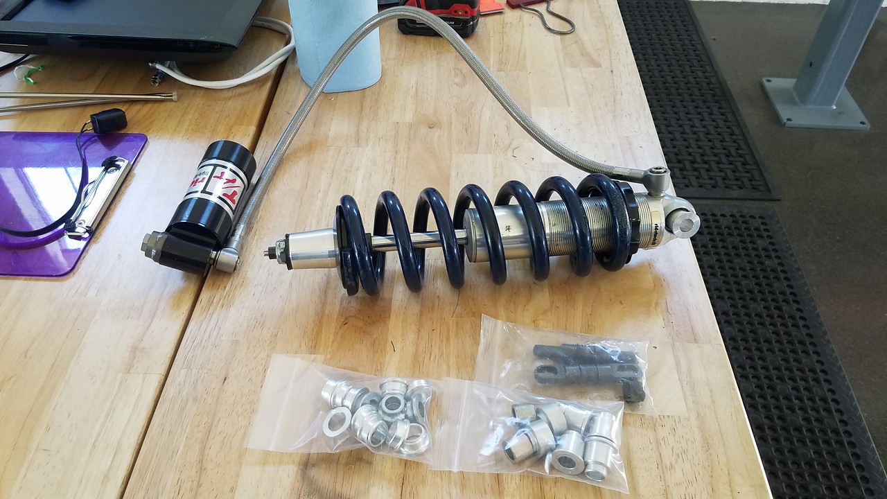
It's a stud top type shock body but should help give you a good idea anyway. Variety of bearing spacers available if needed as well. Just holler...and we'll find a place to meet up.Lance
1985 Monte Carlo SS Street Car
02-11-2019 #6
Registered User
- Join Date
- Jan 2016
- Location
- Chino Valley, AZ
- Posts
- 134
the only thing I would be concerned with, on the rear abr for the lower arm, is turning radius. it looks like you might be selling yourself short. i know the s197 and bmw from arms are more of an L then an A, but still have the two pivot points on the chassis side.
02-11-2019 #7
Registered User
- Join Date
- Oct 2018
- Location
- Phoenix, AZ
- Posts
- 583
Excellent point! I tried to measure for it, but I need to move the rack from lock to lock to verify now. I tried to set the rear arms to have about 1/2" of clearance at full lock. We all know how well I measure.... Originally Posted by frink84
'95 F-150 track ready street beastWant more projects/photos? Check my Instagram
02-14-2019 #8 Registered User
- Join Date
- Nov 2009
- Posts
- 169
Great work, love the project!
64 Mercury Comet
408w boosted
More boost on the way!
02-14-2019 #9
Registered User
- Join Date
- Oct 2018
- Location
- Phoenix, AZ
- Posts
- 583
Thanks for following! Originally Posted by injcted
On that note (you'll like this one injcted) I heard from the engine builder. The crank was delivered yesterday! So in about 2-3 weeks I should bring my forged 408w monster home. If any of you have recommendations for PDMs to make wiring easier, please share.
More soon...'95 F-150 track ready street beastWant more projects/photos? Check my Instagram
02-16-2019 #10
Registered User
- Join Date
- Oct 2018
- Location
- Phoenix, AZ
- Posts
- 583
Getting closer to wrapping up the front suspension.
Today was one of those days where you spend 75% of your time on cutting and shaping little brackets. First bracket up was the upper uniball to clevis pins. Nothing fancy here, but I like it.
Then I started playing around with where everything would mount. Thanks to Lance I had a shock to feel out what interference I might have. Turns out I had to move my upper control arm mount back outboard by about 1/2". No big deal since wider wheels will likely not need much additional backspacing. I'm prioritizing suspension geometry over possible wider wheels here. It was kind of exciting to see this all together for the first time.
After making some measurements and moving mounts around I landed on this
I feel good about how it all came out thus far. Obviously I need to add some material to the top of the frame rail. Thanks a lot Ford for making the most crooked frame ever. I'll see if I have any 3/16" steel plate handy. If not, I can work on finishing the rear end welds until I get some this week. Then onto shock mounts and actually ordering coilovers (Yay!). I really need to find an empty 351w block to make motor mounts too. Clock is ticking there. Anyone know where I can find a bare block for cheap in Phoenix?'95 F-150 track ready street beastWant more projects/photos? Check my Instagram
02-25-2019 #11 Registered User
- Join Date
- Jun 2012
- Location
- South Lyon, MI
- Posts
- 1,244
I was looking at the upper control arm photos. What is to prevent the ball joint assembly from rotating in the two clevises? Normally you would have one clevis and weld the other leg to the flange on the ball joint sleeve. Take a look at SPC upper control arms and some of the circle track uppers. It should be an easy modification from what you have. Originally Posted by Sbeck09
Overall, your craftsmanship is great. This is a very interesting build.Bill Harvey
Scope Creep - 1974 Nova - https://www.pro-touring.com/showthre...rit-of-America
Family Fun - 1955 Belair - https://www.pro-touring.com/showthre...hter-55-Belair
02-25-2019 #12
Registered User
- Join Date
- Oct 2018
- Location
- Phoenix, AZ
- Posts
- 583
Thanks for the kudos! It means a lot. Originally Posted by cornfedbill
You are absolutely correct about the upper ball joint. I actually had to special order some low grade bolts with the correct 5/8-18 thread so I can do exactly what you suggested. They just haven't arrived yet. Hopefully I can get that done this week. We figured the clevis, being high carbon, would be too prone to cracking.'95 F-150 track ready street beastWant more projects/photos? Check my Instagram
02-17-2019 #13 Registered User
- Join Date
- Mar 2014
- Location
- Mesa, AZ
- Posts
- 637
Motor mounts for a 289 & 302 Ford are the same as a 351, so if you can find any of those blocks they will work for motor mount fabrication. I'd call your engine builder and ask if he has a junk one laying around you could use.
I have a 302 block I could loan you, but it's in Yuma and I wont be up to the valley for the better part of a month at this time.Nelson
1969 Chevelle "Cone Smasher" Family Project
https://www.pro-touring.com/threads/...uot?highlight=
1984 "Rustang" GT, 5.0, 5 Speed Project
https://www.pro-touring.com/threads/...T-(Slow-Build)
02-17-2019 #14
Registered User
- Join Date
- Oct 2018
- Location
- Phoenix, AZ
- Posts
- 583
My engine builder only has 1 block and apparently it's valuable for some reason so I declined messing with it. I wanted to find a 351 so I could also check header clearance (taller deck) while making mounts too. Lance came through again and connected me with a guy down the street that has a well used bare block for $30. I'm picking it up tomorrow afternoon. Problem solved.
Thanks for the tip though!'95 F-150 track ready street beastWant more projects/photos? Check my Instagram
02-17-2019 #15
Registered User
- Join Date
- Oct 2018
- Location
- Phoenix, AZ
- Posts
- 583
Somebody gets to say I told you so....but first I got the arms 90% completed today!
For starters I did have some strips of steel handy that would work so I grafted it on and measured everything 10 times before welding the first side on. This is at 0 degrees of camber and 6 degrees of caster for ride height. Took a ton of curse words just to do this much welding. My poor wire welder is not happy at all. It kept stopping feeding wire and then would stop letting shield gas flow. I'm going to try and have it serviced in the hopes it brings it back.
After reveling in the glory of coming this far I had to cycle it to make sure I could confidently move onto the passenger side.
Check. Smooth as glass. Zero bind. I couldn't be happier.
So a couple hours later I was able to replicate this for the other side and see how this crazy concept turned out.
I'm lovin it! Already looks mean being low with 275s sitting there.
Now the "I told you so" award goes to frink84. I thought I accounted for full steering lock on the rear of the lower control arms. Fail. They are about 1/4" too far back. No biggy I just get to cut and move them forward slightly. But you can say it buddy. You were right.'95 F-150 track ready street beastWant more projects/photos? Check my Instagram
02-19-2019 #16
Registered User
- Join Date
- Jan 2016
- Location
- Chino Valley, AZ
- Posts
- 134
Woo! Though in this case I hate to be right, as it's more work for you. Originally Posted by Sbeck09
02-17-2019 #17
Registered User
- Join Date
- Apr 2011
- Location
- Rosser Manitoba Canada
- Posts
- 338

You need to redesign your upper control arms. They will fail in use as they are designed. One of the arms has to be solid to your spherical bearing. I didn't look at the bottoms, but they may need this also. Welding one clevis probably wont work as the material they are made of is incredibly hard.
02-17-2019 #18
Registered User
- Join Date
- Oct 2018
- Location
- Phoenix, AZ
- Posts
- 583
Excellent catch. I was actually planning to weld the front clevis on each side. These are supposed to only be zinc plated carbon steel (QA1) so I thought it would be fine. If you know something here that I don't, please share more! Originally Posted by egoman
Lowers can't have this issue since the forward arm is welded solid to the bearing sleeve.'95 F-150 track ready street beastWant more projects/photos? Check my Instagram
02-18-2019 #19
Registered User
- Join Date
- Oct 2018
- Location
- Phoenix, AZ
- Posts
- 583
OK so dug into welding high carbon steel to mild steel. Totally doable, but best practice seems to be preheating slowly and then using post-heating to let it very slowly cool. Otherwise you can end up with cracking at the weld. I think I'm going to try it.
If anyone knows otherwise please stop me. I'll be working on this in a couple days.'95 F-150 track ready street beastWant more projects/photos? Check my Instagram
02-18-2019 #20
Registered User
- Join Date
- Apr 2011
- Location
- Rosser Manitoba Canada
- Posts
- 338
https://www.walmart.com/ip/Allstar-P...56298/52240993
This is the general idea. When I build these I just extend the tubing to the threaded ring. That would save you 2 clevises to build more A-arms with. If you insist on welding the clevis we used to heat these to red hot and let them cool to take the "Hardness" out of them before welding.
Tags for this Thread

 Reply With Quote



