

Results 1 to 20 of 39
-
09-25-2013 #1
 Registered User
- Join Date
- Jul 2013
- Location
- Houston TX
- Posts
- 32

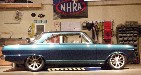
My '64 Nova SS build- from scratch.
http://i1287.photobucket.com/albums/...ps9c6eb07b.jpg
I picked this car up a few months back out of Fort Worth Tx. The plan was to get it running as is and enjoy it. Well, after I replaced the tires and the entire fuel system from fuel filler all the way to the carb, the condition of the wiring and the 250ci engine was just too rough.
I had plans to make this a hardcore driving machine since before I even bought it, so the time came to turn my visions into reality. The overall plan is basically pro-touring, but more racey. Amazing suspension, big power, cage, simple interior, simple exterior, super functional. My biggest goal for this car is functional. If I cant drive it to work in the rain it isn't want I want. At the same time, if it isn't easily made track legal, it isn't what I want either. I'm hoping to get the give and take just right. I managed to get it pretty much perfect on my last build when I shot for more of a sport truck build...as seen at many Good Guys shows and magazines.
http://i1287.photobucket.com/albums/...ps2b7a7b64.jpg
Unfortunately, I recently graduated college in mechanical engineering so money is super tight; off my parents payroll. Luckily, I have a want for creating things from scratch that is as good as or maybe even better than what is sold pre made.
I've been putting pen to paper for the last several months designing a complete front sub frame to get my build started with. I designed around c5/c6 corvette parts. Orignally I planned on only using the corvette uprights, wheel bearings, and brakes....but because I had to relocated away from my families wealth of tools, I opted for a redesign and will be using stock vette control arms.
In total, I have about 200 hours of design work in the sub frame. This includes setting up the geometry to actually drawing the front end in 3D space in a manor than I can fabricate myself with very limited tools. The hydraformed cross member of detroit speeds sub is probbably the most elegant solution, but I did what I could.
Heres some views of what I've come up with so far. As the build progresses so will my model.
http://i1287.photobucket.com/albums/...psec572b77.jpg
http://i1287.photobucket.com/albums/...ps3f3ccf8a.jpg
http://i1287.photobucket.com/albums/...ps0c299dd6.jpg
I will be using an LS engine with a T56 trans and I've incorporated the engine into the design so I have a good fit.
http://i1287.photobucket.com/albums/...ps054f6a87.jpg
http://i1287.photobucket.com/albums/...ps27a71df4.jpg
You can see the mustang manual rack in the last picture. The driver side mount naturally wants to exist where the lower bushing is on the vette control arm. To get by this problem I will be making a new mount further inboard as shown that clamps on the rack body. I'll cover this more this weekend.
So far I have completed the basic design and sent all my burn files to my brother, who fortunately has a cnc plasma table. Unfortunately, he lives 3 hours away.
The precision in these cuts are what will allow me to build this front end without intricate jigs.
http://i1287.photobucket.com/albums/...pse2983226.jpg
They're many more pieces than this but these are all the pictures I have so far.
This weekend I will be traveling to pickup the cut parts from my brother and heading all the way back to my parents house where our lathe is, which I will use to move the mount on the steering rack.
I'll keep you guys updated as long as someone is paying attention. So stick around and let me know what yall think!
-Dustin
-
09-25-2013 #2
Registered User
- Join Date
- Oct 2012
- Posts
- 164

Hope you are using some seriously strong steel!
Looks cool so far, I'm jealous of your ability. lol
09-25-2013 #3 New to Pro-Touring
- Join Date
- Sep 2013
- Posts
- 31
not bad. id design where the subframe is going to bolt to the body better. Im a engineer as well. are you using solid works or inventor? what are you going to do about the upper and lower control arms?
09-25-2013 #4
Registered User
- Join Date
- Jul 2013
- Location
- Houston TX
- Posts
- 32
What concerns you?
I use solidworks.
Control arms are stock vette c5/c6.
09-25-2013 #5
Registered User
- Join Date
- Oct 2012
- Posts
- 164
Wish I was smart enough and focused enough to be an engineer. lol
09-26-2013 #6 Registered User
- Join Date
- Aug 2004
- Location
- Crown Point, Indiana
- Posts
- 1,107
My '64 Nova SS build- from scratch.
Wow great ideas got my popcorn ready to enjoy!
09-29-2013 #7 Registered User
- Join Date
- Sep 2013
- Posts
- 1

was going to shoot the arms C5 prices on ebay! grand design!!
09-30-2013 #8
Registered User
- Join Date
- Jul 2013
- Location
- Houston TX
- Posts
- 32
got a ton done this weekend...but didn't take as many pictures as I thought. I will get some more tonight to help better explain what all happened. My brother helped me quite a bit so it was hard to keep up.
I ripped the flaming river quick ratio rack apart. Got it fixed up in the lathe and trued up the body for the clamp.
http://i1287.photobucket.com/albums/...psadd74678.jpg
http://i1287.photobucket.com/albums/...psdda75f33.jpg
http://i1287.photobucket.com/albums/...ps54eec8aa.jpg
I also drilled and tapped a hole through each clamp half into the rack for better engagement. I'll get more pics of this. The clamp extended past the aluminum body of the rack and onto the steel center tube so I machined a plastic bushing to fill the gap instead of trim the clamp shorter.
http://i1287.photobucket.com/albums/...ps9aee5711.jpg
I'll get more pics of how this installs.
machined 8 spacers for the UCA bushing mounts. these are my contingency plan since this is my first front end and the geometry isn't 100% confirmed...my model is only as accurate as the stock measurements I have from various sources.
http://i1287.photobucket.com/albums/...ps6a8d77b1.jpg
http://i1287.photobucket.com/albums/...psa38096c2.jpg
faced/drilled/tapped the LCA mounts. only have a pic of them mounted up in chuck though, I'll get some more...
http://i1287.photobucket.com/albums/...ps03802c62.jpg
lastly we machined the pinion down shorter. machined a positive on one side and a socket in the other. Took ~3" out. Press them together and TIG welded. First pass fusion, then two filler passes.
http://i1287.photobucket.com/albums/...ps6537f17c.jpg
http://i1287.photobucket.com/albums/...ps84fc2bda.jpg
and that's all the pictures I have with me. I'll fill in the blanks tonight.
Should get building structure soon. I mocked some stuff up as well...but of course no pictures!
09-30-2013 #9
Registered User
- Join Date
- Jul 2013
- Location
- Houston TX
- Posts
- 32
whoops
09-30-2013 #10
Registered User
- Join Date
- Jul 2013
- Location
- Houston TX
- Posts
- 32
test- it's not letting me post an update? says a mod must approve?
got it....can't use thumbnail pictures?
09-30-2013 #11
Registered User
- Join Date
- Jul 2013
- Location
- Houston TX
- Posts
- 32
x2.
10-01-2013 #12
Registered User
- Join Date
- Jul 2013
- Location
- Houston TX
- Posts
- 32
x3.
10-01-2013 #13
Registered User
- Join Date
- Jul 2013
- Location
- Houston TX
- Posts
- 32
x4.
10-01-2013 #14
Registered User
- Join Date
- Jul 2013
- Location
- Houston TX
- Posts
- 32
Whoops
10-01-2013 #15
Registered User
- Join Date
- Jul 2013
- Location
- Houston TX
- Posts
- 32
Whoops x2.
10-01-2013 #16
Registered User
- Join Date
- Jul 2013
- Location
- Houston TX
- Posts
- 32
Got some non-car things done also. I need a solid foundation to build on so I made one.
solid 3/8 top with 1/4 everything else. 3'x4'...Its a beast. Adjustable feet so I can get it level easily. Big thanks to my brother for cutting (most of) it out.
http://i1287.photobucket.com/albums/...psd110b21b.jpg
http://i1287.photobucket.com/albums/...ps59eb2199.jpg
http://i1287.photobucket.com/albums/...psc4533c14.jpg
http://i1287.photobucket.com/albums/...psbc22e758.jpg
http://i1287.photobucket.com/albums/...ps5a4e9e97.jpg
http://i1287.photobucket.com/albums/...psfa2d342b.jpg
I have an eyehook in the center so I can move it by myself with my hoist. Without this eyehook, I think it would take 3-4 guys at least.
http://i1287.photobucket.com/albums/...ps0d721a26.jpg
loaded up with material for the subframe.
http://i1287.photobucket.com/albums/...ps4002a7f2.jpg
tonight I will start work on the main frame rails. hopefully I can get them cut and fit and tac'd up and positioned on the table. I'm going to build this subframe upside down until the lower crossmember is more or less 'done'. Then flip it over and do the upper control arm mounts.
10-01-2013 #17
Registered User
- Join Date
- Oct 2012
- Posts
- 164
Triple post.
LOL
Looking good man.
10-01-2013 #18
Registered User
- Join Date
- Jul 2013
- Location
- Houston TX
- Posts
- 32
Ah! I have been having problems posting.
Thanks!
10-02-2013 #19
Registered User
- Join Date
- Jul 2013
- Location
- Houston TX
- Posts
- 32
got busy on the frame rails yesterday.
cut all the 2x4 down to size then shaped the front pieces. My rail is higher than stock so that I can have shorter upper control arm mounts and more steering rack clearance, which means I needed to step the rail down for the core support. I also angle cut the front to fit in the core support and capped the front of the rails so that box tube would hole its shape better. It was wanting to flare out when I cut the ends. eventually I will cap the angle but I'm going to plug weld in some 1/4 material to the backside of the 1/8 tube so that when I finish drilling and tapping the bumper and core support holes, there is ~3/8" of material to thread.
http://i1287.photobucket.com/albums/...ps6866e25c.jpg
http://i1287.photobucket.com/albums/...psde95cfc5.jpg
http://i1287.photobucket.com/albums/...pseaf52862.jpg
http://i1287.photobucket.com/albums/...ps497de72f.jpg
http://i1287.photobucket.com/albums/...psd7a815cd.jpg
I used some extra tube to clamp against when forming the rails. The front pieces are offset to get the correct width at the bumper so I used pieces of flat plate as spacers. Worked well.
http://i1287.photobucket.com/albums/...ps8a127be9.jpg
welded and ground the top, then flipped it over and did the bottom.
http://i1287.photobucket.com/albums/...psc7fccdc0.jpg
ready for the scab plates to finish the offset.
http://i1287.photobucket.com/albums/...ps9f1a567f.jpg
I'll get the rails finished today probably. Then I can clean the table and start setting up the fun stuff.
10-02-2013 #20
Registered User
- Join Date
- Mar 2010
- Location
- Orange County, CA
- Posts
- 31
Looks great, nice job on the CAD design and fabrication. I'm also a mechanical engineer and have done a bit of CAD designing on my cars, but havent gotten to fabbing anything yet having just bought a house. I need to build me a table like that to get me motivated!
Where did you get the CAD models of the engine and rear?

 Reply With Quote