Results 21 to 40 of 252
-
10-23-2011 #21

 Registered User
- Join Date
- Apr 2006
- Location
- Atlanta GA
- Posts
- 7,477
of all people im happy that you were the one who won all that good stuff man.. for real..
-
10-25-2011 #22 Registered User
- Join Date
- Mar 2007
- Location
- Florida
- Posts
- 2,391
 Thanks! Now I've just gotta keep moving forward and put it all to use!
 Originally Posted by Mr.VENGEANCE

I was stuffing a lot of tire in stock wheelwells up front with the 275's on 9.5" rims and now I'm going to try 285's on a 10", so backspacing is important. I could touch the swaybar with the tires at full lock and it rubbed the powdercoating off. I'm concerned about backspacing when ordering the new wheels so I haven't ordered them because I was afraid if the new brake combo moved the wheel flange out I'd be in big trouble. So I figured better to install the new brakes and spindles and measure before ordering. I will loose some more turning radius and plan on installing limiters on the lower control arms. The types of driving I do with this car don't require extremely sharp turns.
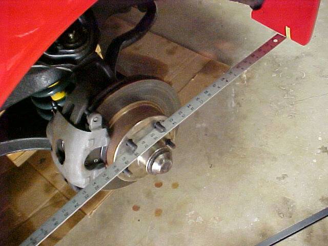
With the original spindle and rotor still in place I used a straight edge to put some tape markers on the car and floor so I could line up the new combo and see if there was a difference.
The first step involved in swapping out the spindle assemblies is removing the brake lines at the frame mounts where the flex tubes end. Since I replaced the flex lines with braided about a bit over a year ago I figured everything should come apart easy, right? WRONG! LOL The passenger side gave me a hassle so I did what anyone irritated would do, yup, I got a big pair of linesmans pliers and cut the hardline. AHAHAHA. I make new brake lines all the time so no big deal. Just would have been nice not to have to make that one from the line lock solenoid over to the passengers side since it was fairly new.
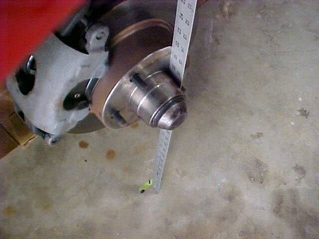
So after making quick work of the stubborn brake line I moved on to removing the spindles with everything attached. The Baers come all set up on a new spindle so all thats necessary to swap the setups is loosening, separating, and then unbolting the tie rod end and upper/lower ball joints. After putting the new assembly in place I checked my tape marks and was pleasantly surprised to find no change in the wheel flange position so I can easily calculate backspacing for the new Rushforth wheels based on the old wheels.
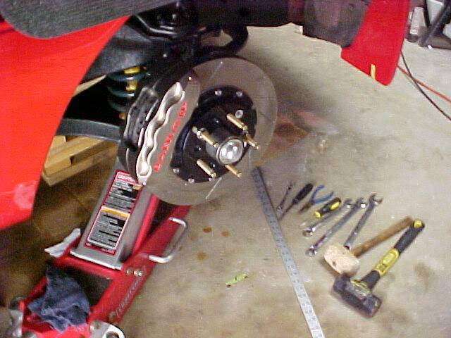
Because I'm concerned about weight I weighed the stock vs. Baer spindle assemblies fully loaded. I got out the bathroom scale and picked up one of each and weighed myself and a piece to be sure I was in the accurate range of a bath scale. I was shocked to find that the new ones were actually LIGHTER than the smaller stock rotor size ones! In disbelief I then piled both old ones on the scale then both new ones. Sure enough! The Baer assemblies with giant rotors are about 1-1 1/2 lbs LESS than stock for each assembly! While the rotating mass is heavier because of the much bigger rotor the overall unsprung weight is lower so in theory there would be some slight handling improvement and a beneficial loss of front end weight helping the front/rear weight bias.
10-25-2011 #23 Registered User
- Join Date
- Jun 2011
- Location
- St. George, Utah
- Posts
- 1,629
Wow! I'd have expected the stock ones were lighter too. Awesome, good whoa and lighter rolling mass too! Woohoo!
10-26-2011 #24 Registered User
- Join Date
- Jan 2008
- Location
- Charlotte
- Posts
- 1,295
Looking good.
2005 LeMans Blue Corvette w/ T56 & Z51 & C6Z06 Brakes, Build Thread: https://www.pro-touring.com/showthread.php?64496
2005 GMC Sierra 2500HD LLY / Allison
2014 Chevy SS LS3 / 4 Door
10-26-2011 #25
Registered User
- Join Date
- Mar 2007
- Location
- Florida
- Posts
- 2,391
Turning radius limiters
As I mentioned in my last post the 275 17's would hit the Hotchkis sway bar at full lock. The new 285 18 Yokohama tire is 10mm wider and will be on a 1/2" wider rim. The "extra" tire has to go to the inside because I was already at the limit on the outside and moving the tire out at all would result in the tire rubbing the fender lip under max compression.
Having the tire hit the swaybar could potentially be very dangerous. As an example, if I was on track and trying to control a situation where some or all of the wheels were at their limit of adhesion and a front tire contacted the swaybar it might cause that wheel to skid. That would be BAD! Lets say the rear end got loose in a corner and I was trying to correct by steering into the slide. The inner front tire (with less weight on it and therefore less grip) would contact the swaybar possibly locking up that wheel, then I'd probably be 4 wheels off before I even knew what happened!
So here's the rub.
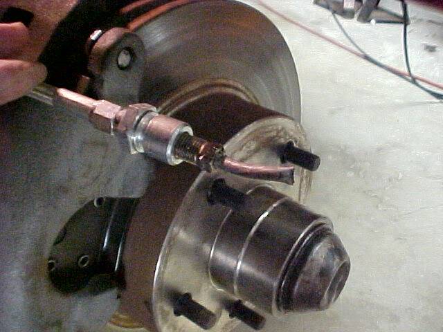
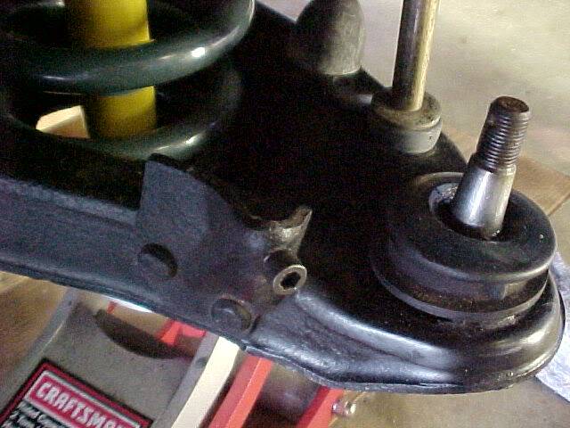
Below is the stock limiter that the spindle bumps into at the end of it's turning radius. The one on the left side limits left turns (right wheel hitting swaybar) and vice versa for the right.
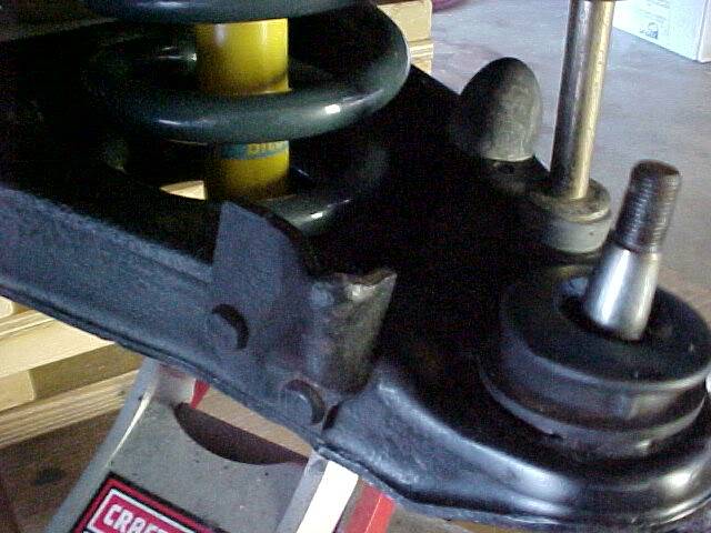
I decided to drill and tap the stock limiter for a 5/16" bolt or threaded rod and use that as a variable adjuster so I can retain as much turning radius as possible. Once the new Rushforth/Yokohama combination is in place I'll adjust the turning radius limiters and lock the adjusters (probably spot weld) so they can't move or loosen up and fall out. "Why 5/16" bolts?" you might ask. Well, 1/4" might bend, and 3/8" would be hard to drill and tap due to the geometry of the stock limiters, also this is a pre metric car so no metric stuff if possible.
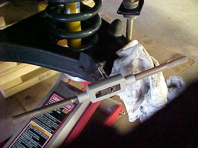
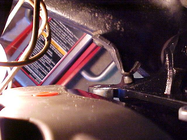
Pics below show an Allen head bolt in screwed into the limiter but I haven't decided what will be used for sure yet. The final pic is looking down from the top so you can see how the spindle travel is limited.
10-26-2011 #26
Registered User
- Join Date
- Jun 2010
- Location
- Georgia
- Posts
- 2,215
Originally Posted by NOT A TA
I have bolt bin envy!
10-26-2011 #27 Registered User
- Join Date
- Dec 2006
- Location
- oshawa ontario
- Posts
- 1,607

awesome updates.....Im glad to see you getting black header sidepipes.....pure badazz!....WAY better than the chrome
Nascar 69 Chevelle project, 1999 Hutch Pagan Nascar chassis, 69 Chevelle body,700hp, Penske's, slicks, roadrace track day https://www.pro-touring.com/showthre...le-Cup-project
89 Iroc 406 Fitech 5 spd
01 chevy 2500HD 4x4 8.1 Allison
31 Scarab 2 x 454
10-27-2011 #28 Registered User
- Join Date
- Aug 2007
- Location
- Roanoke (FortWorth) Texas
- Posts
- 786
Allen head is a bad idea. You booger it up and you'll never get it back out.... Just my thoughts.
ChrisTotal Cost Involved - Ridetech - Fatman - Total Control Products - Gateway Performance - MaverickMan Carbon
11-11-2011 #29
Registered User
- Join Date
- Mar 2007
- Location
- Florida
- Posts
- 2,391
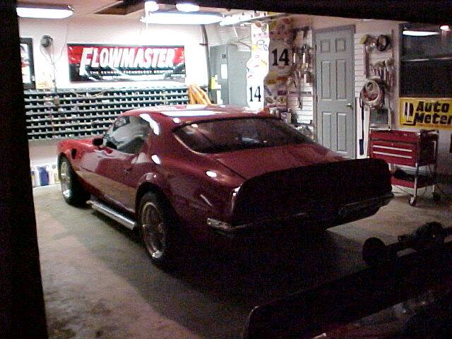
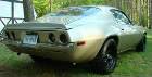
I'd prefer chrome, but thats probably not going to happen. Black pipes will make the car look like it's higher off the ground so I probably won't leave them black. It's an optical illusion. Those who were around in the 70's may remember the flat black rocker panel trend, I did it to my 68 Camaro and it instantly looked like it was higher off the ground. As you can see in the pic in my first post my car is not really very low at all as it is compared with the current drop & tuck trend in the PT community. I've even been told I have too much "gap" above the tire. I care more about performance and it seems fine as is on track and at the same time the sidepipes make it appear lower than it actually is because the bottom of them is lower than the rockers. The effect is noticable more in person than in pics. Originally Posted by shortrack
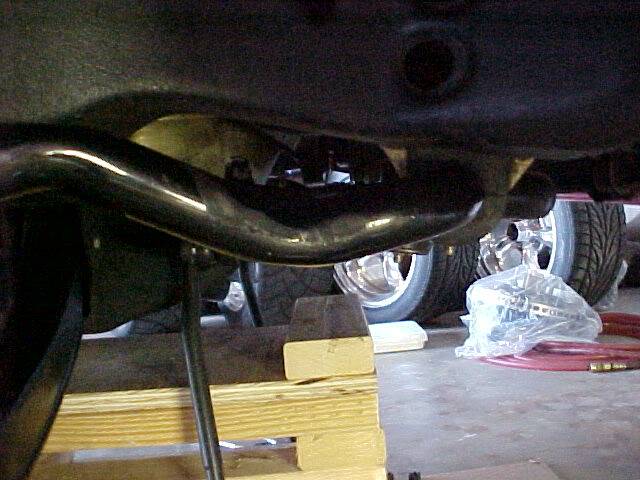
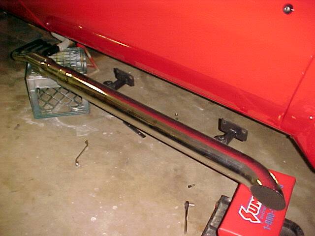
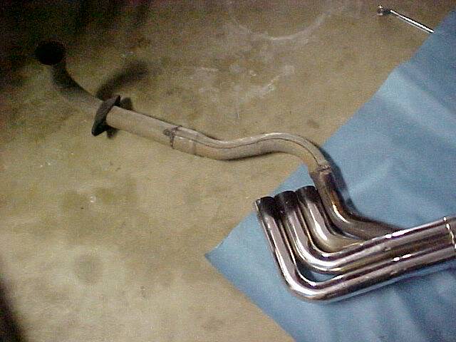
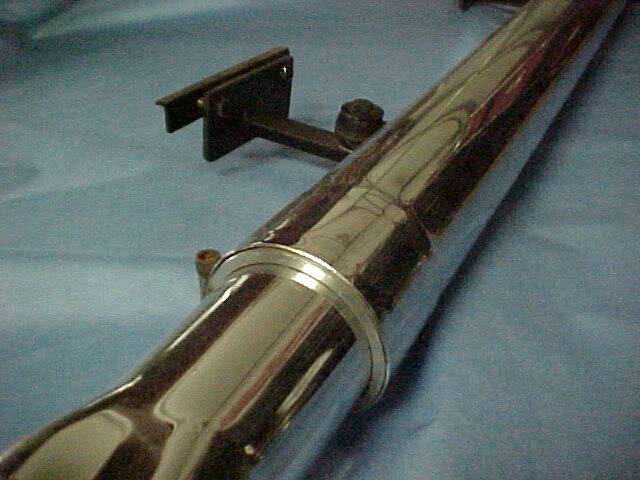
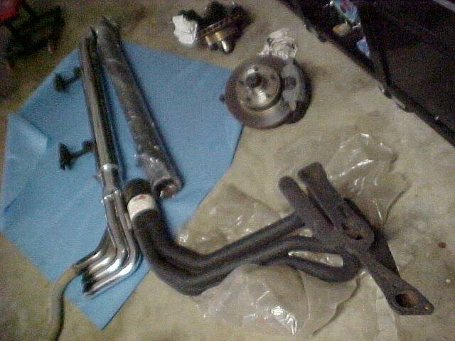
Because I care more about performance I'm giving up the chrome pipes even though I really like the look of them. As you can see below the front section is just a faux header with only one of the tubes flowing exhaust. When I originally installed them I had the stock 350 2V engine with a single stock exhaust system. So upgrading to actual "dual" exhaust was a big step up ! AHAHAHA Even using stock exhaust manifolds! Since then I installed a bigger engine which is limited by the exhaust and the small (575 CFM) carb I've been using with the chrome setup. Car runs great and drivability is good. Throttle response is great but I'm leaving a lot of available power unused because the engine is kind of corked up.
The chrome pipes are great for an around town cruise night car and I've run high 13's at the strip and up to 140 MPH on road courses and at land speed races so for what I was doing before they were fine. Now that I've got all the safety equipment in place to run up near 200 MPH I'll be building for more power eventually and the new full headers will be necessary. You just can't easily push enough air through stock Pontiac D port exhaust manifolds to make 600-700 HP.
So anyway, here's my old setup. The front and rear sidepipe sections were NOS pieces when I installed them but were from 2 different sets. They were different diameters. I had aluminum spacer collars made close to size by a bud in a machine shop then hand sanded them to an interference fit. I had a local exhaust shop bend up the sections that run from the faux header sections to the stock exhaust manifolds. I fabricated some T shaped mounting brackets that get bolted to the pinch weld at the bottom of the rockers. I used sway bar end link bushings to mount the pipes to the brackets so the engine movement and flex of the car over uneven roads etc. wouldn't crack the pipes.
Last edited by NOT A TA; 05-10-2014 at 05:44 PM.
11-14-2011 #30
Registered User
- Join Date
- Mar 2007
- Location
- Florida
- Posts
- 2,391
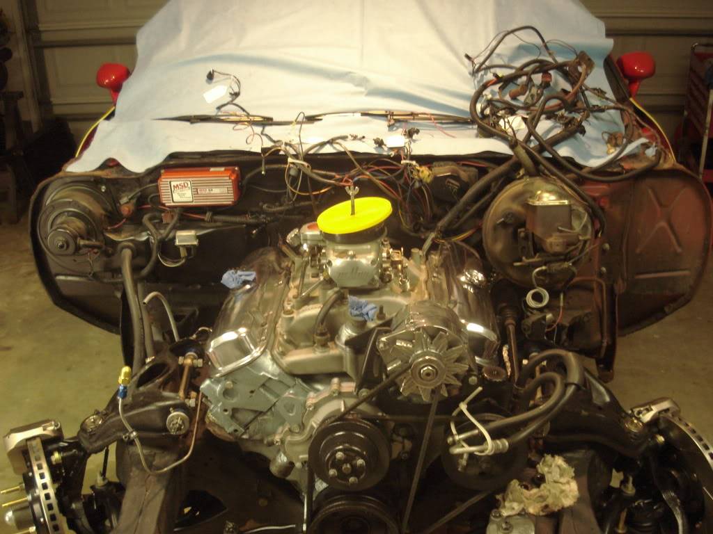
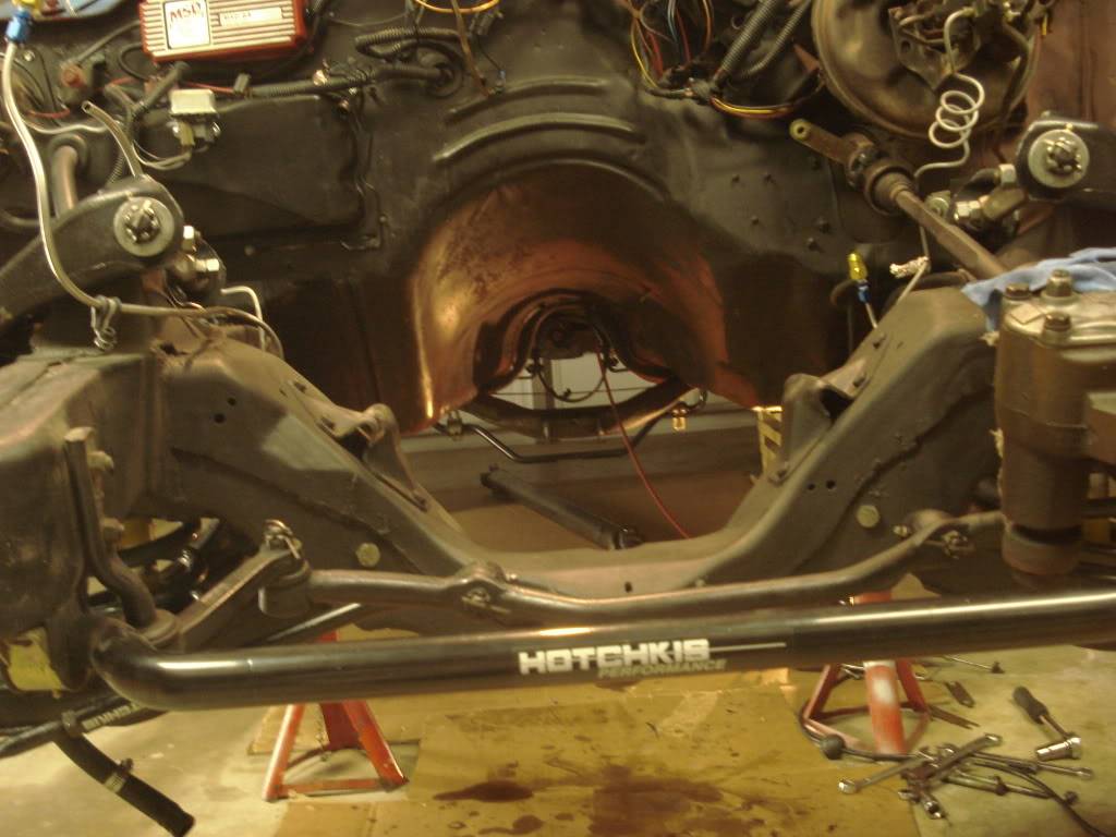
To replace the core support on this car everything from the firewall forward has to come off except one fender. On most old cars that's not too bad of a job but the early 2nd gen birds with a front spoiler have a lot of pieces and LOTS of bolts! So a couple hours here and there over the past couple days when I had time and it's all off. Since I will be pulling the engine/trans and running lots of new brake lines etc I figured there was no good reason to leave one fender in place so I just took everything off.
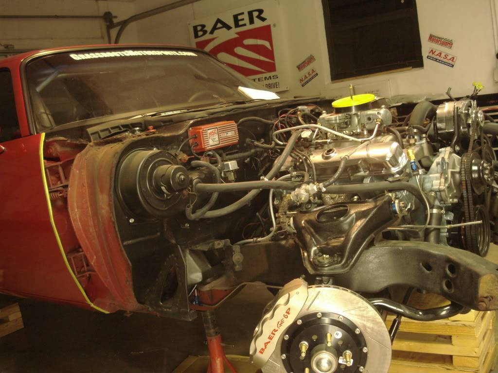
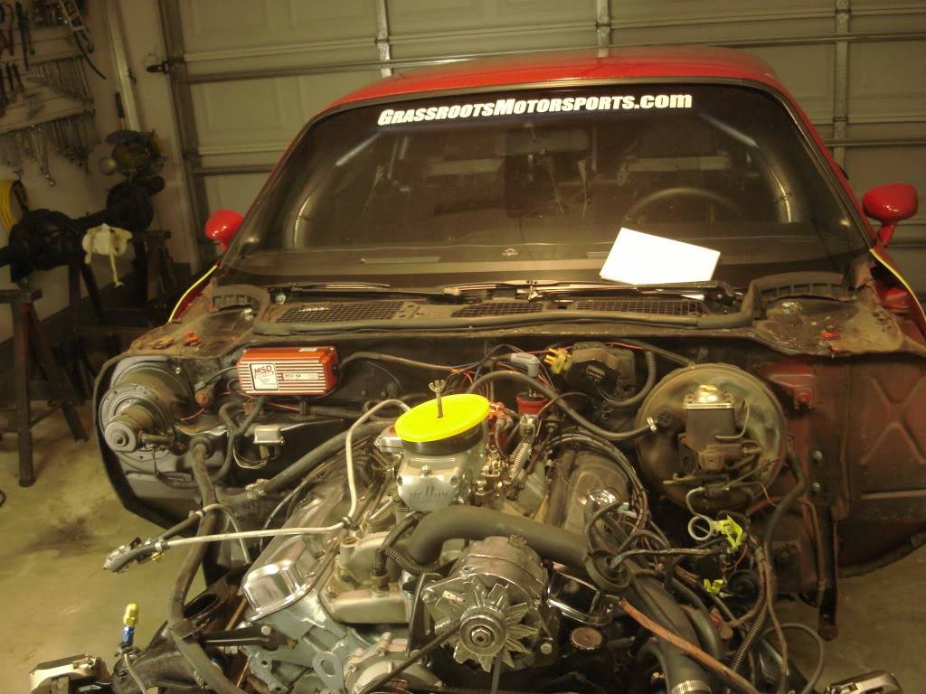
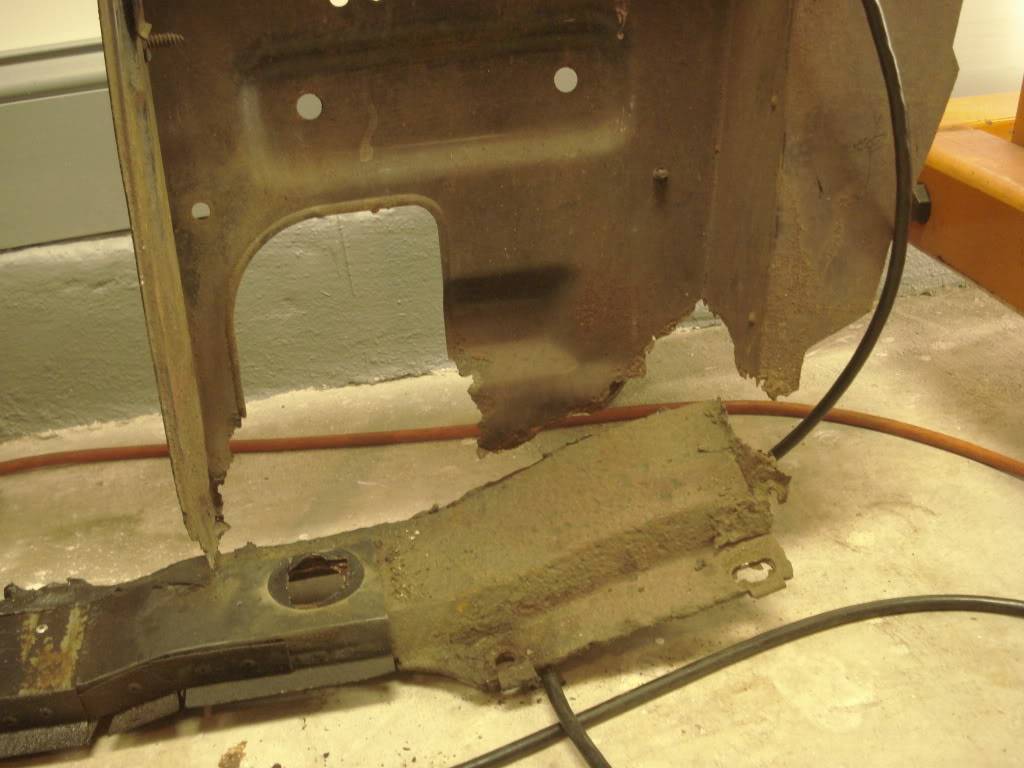
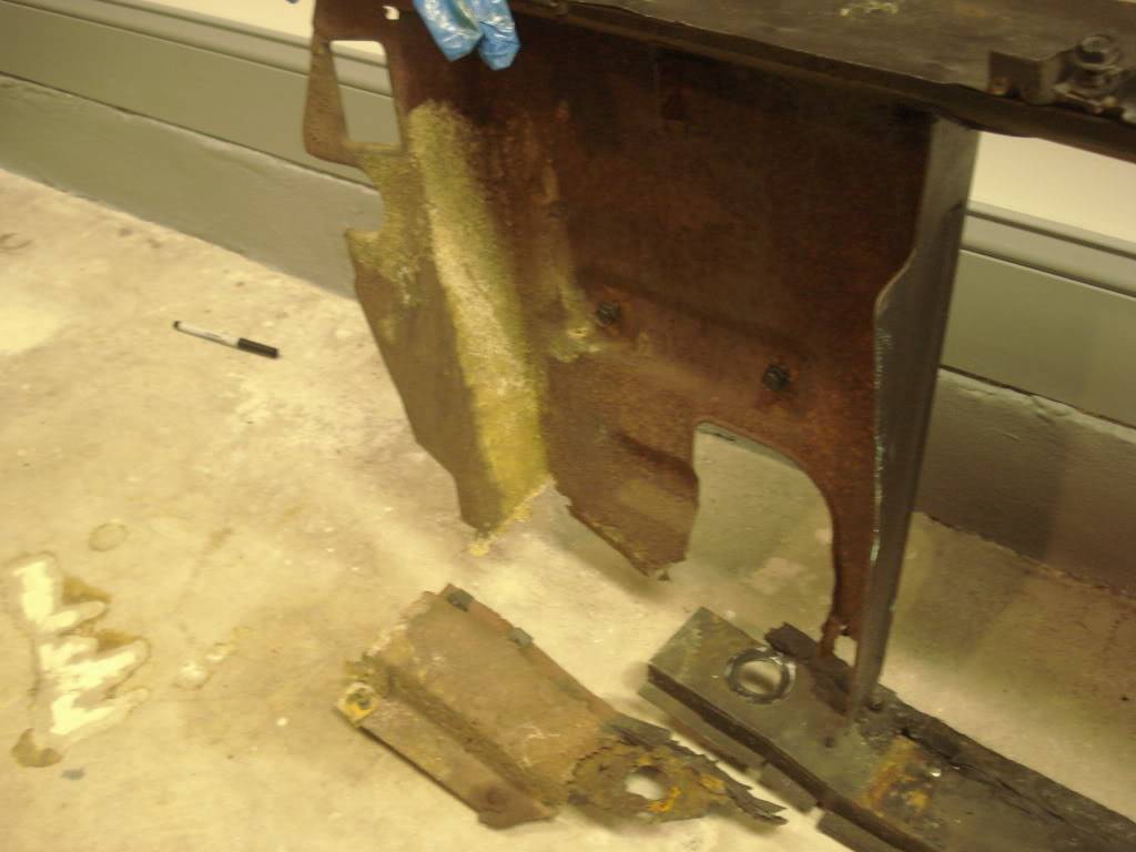
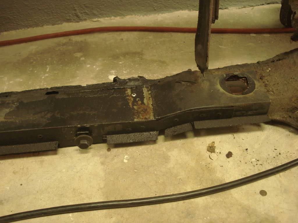
In previous posts you saw the new (to me) core support. These early 2nd gen Firebirds were notorious for rusted out core supports. The wide openings under the bumper with no grills allowed leaves, papers etc. to fly in and hit the radiator then drop when the car stopped only to slowly rot there because there was no place for the debris to get out. It just sat wet from rain and washing on the lower part that holds up the radiator. The core support was the worst part on my car when I bought it, and remained the worst until today, while pretty much everything else on the car was reconditioned/replaced.
Many, many years ago I made a sheet metal section from frame rail to frame rail to support the radiator and eventually found a pretty good core support to replace the original with. BUT, I knew how big a job it was to replace and procrastinated, year, after year, after year. AHAHAHA So here's the pics of the rusty one. Due to rust the only thing connecting the top and bottom is the latch support bracket which will be refurbished and moved onto the new core support.
Last edited by NOT A TA; 05-10-2014 at 05:45 PM.
11-14-2011 #31 Registered User
- Join Date
- Nov 2005
- Location
- Little Rock, Arkansas
- Posts
- 945
Good Lord man! That thing was gone. I bet the front end sheet metal waved around like a flag in the breeze at speed. Good to see the progress.
11-14-2011 #32 Registered User
- Join Date
- Feb 2005
- Location
- Sydney, Australia
- Posts
- 1,798

I agree, Chris...considering how fast he's been pushing that car I'm surprised the front sheet metal didn't end up wrapped around the windscreen, lol.
Regards,
Leigh
Sydney, Australia
1971 Firebird 455
https://www.pro-touring.com/showthre...Project/page27
11-15-2011 #33
Registered User
- Join Date
- Mar 2007
- Location
- Florida
- Posts
- 2,391
Well, looks like you guys are paying attention! Or, at least enjoying the pics! AHAHAHA
When I started this thread I debated whether or not to get involved with "The rest of the story" or just stick to the brakes, wheels, and tires install. Most of us don't own "perfect" cars, and we each know what our car needs or what we want to do to make it better. For many of us the upgrades or repairs get ignored or pushed off "till I have time" or "when I have the money", and I'm no different. I figured posting about the repairs and other upgrades would be beneficial to some and perhaps interesting, entertaining or informative to others. I won the contest because I had a cool picture of me out driving my car at Sebring. I never would have had that opportunity if I waited till my car was perfect and by not waiting my car will be closer to my idea of perfect sooner with the Baers, Rushforths, and Yokohamas.
As for the core support and front end. It was very strong and didn't move around much at all. I pushed hard on it to be sure my car was solid whenever using jackstands and never noticed any flex. I doubt it moved more than a stock bird. The way all of the pieces bolt together creates a strong structure of folded sheetmetal with several horizontal supports and the center vertical latch bracket along with my tow hook bracket which ties the frame rail mounted bumper supports together. I've worked on other 2nd gen F bodies (drag cars) with most of the core support cut out to reduce weight and noticed there was little affect on the integrity. If you think about it the whole subframe is just hanging on 6 rubber bushings from the factory. So out front, there was no solid, rigid body support to the subframe, the front end sheetmetal was bolted to the firewall. I've always wondered if there would be a change to the front/rear weight bias if the front sheetmetal was attached only to the subframe instead of hanging like a ledge from the firewall trying to lift the rear of the car due to the weight forward of the front wheels.Last edited by NOT A TA; 05-10-2014 at 05:46 PM.
11-15-2011 #34
Registered User
- Join Date
- Mar 2007
- Location
- Florida
- Posts
- 2,391
I've got all the wiring, fuel system, and accessories ready to pull the engine so will probably do it tomorrow after I drain the transmission. The patient is ready for the operation!
Last edited by NOT A TA; 05-10-2014 at 05:47 PM.
11-15-2011 #35
Registered User
- Join Date
- Feb 2005
- Location
- Sydney, Australia
- Posts
- 1,798
Too late for regrets now....rip into it, mate!!!!!
Regards,
Leigh
Sydney, Australia
1971 Firebird 455
https://www.pro-touring.com/showthre...Project/page27
11-16-2011 #36 Registered User
- Join Date
- Aug 2004
- Location
- Rustburg, Virginia
- Posts
- 3,436
John,
Good write up you have going here...keep it up. I've been following along with your progress by being subscribed to this thread and reading the emails on my phone. Never really looked into it, but how much trouble would it be to fab a core support out of square aluminum tubing, like Bad Penny and a few others have? I was just thinking that it may save some weight on the front tires, plus be as strong or stronger than the stock piece. Wish I could think of a 2gen with one of these to post pics of, but none come to mind as the moment.1970 RS/SS350 139K on the clock:
89 TPI motor w/ 1pc rear seal coupled to a Viper T56 via Mcleod's modular bellhousing w/ hydraulic T/O bearing from the Viper, 12 bolt rear w/ 3.73 gearing, SC&C upper control arms, factory lowers with Delalums, C5 brakes at all four corners, Front Wheels 17x8's with Sumi 255/40/17 and Rear Wheels 17x9's with Sumi 275/40/17.
Brief description of the work done so far can be found here: http://www.nastyz28.com/forum/showthread.php?t=112454
11-16-2011 #37
Registered User
- Join Date
- Mar 2007
- Location
- Florida
- Posts
- 2,391
Originally Posted by John Wright
Thanks John! When Ty's Freedom Bird was being built we used my spare core support to take pics and get all the dimensions from so Jim at Autorad in GA http://www.autoradradiators.com/ could custom make an aluminum core support for that car. I don't know if he added it to his offerings as a regular piece but he does offer them for the 70-73 Camaro. Once again, Camaro's get the love! LOL The stock core support weighs about 21 lbs. unfortunately I don't think anyone ever weighed the one in Freedom Bird. Maybe Chad, Ty, or Jim will chime in. Getting involved myself in fabricating an aluminum one with my level of skills would extend my overall project time substantially.Last edited by NOT A TA; 05-10-2014 at 05:48 PM.
11-16-2011 #38
Registered User
- Join Date
- Dec 2008
- Location
- Lehigh Valley Pa
- Posts
- 1,269
Keep the info coming. I love the steering limiter. I was going to just weld on mine but like your idea better.
1996 Federal Cadillac hearse
1988 Eureka Chevy hearse
11-21-2011 #39
Registered User
- Join Date
- Mar 2007
- Location
- Florida
- Posts
- 2,391
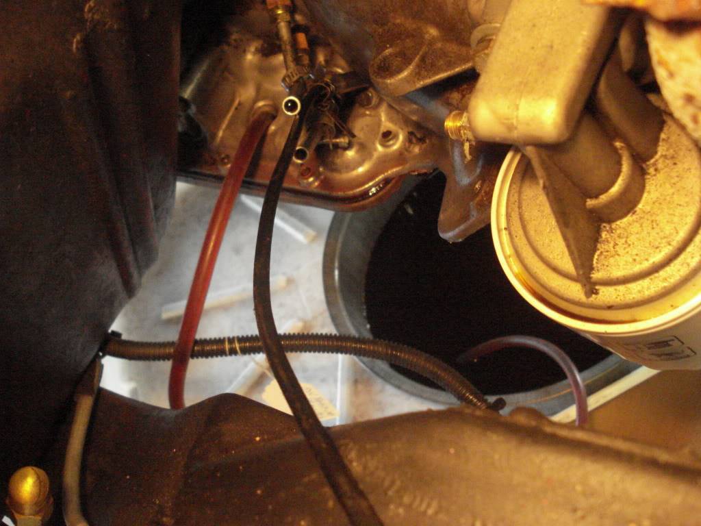
I pull engines fairly often and I don't like a big mess. The first thing I do is go to the local appliance store and get a large box from a refridgerator to cut up and lay under the car. If one piece gets all soaked with a fluid I've still got 3 more to make another mess! Siphoning certain fluids is another thing I do to keep things clean and neat. Most (but not all) radiator petcocks are not in a place that's both easy to reach and they don't usually pour the fluid in an open enough area to easily collect the fluid without it running all over suspension/steering components or the frame or core support creating multiple waterfalls under the car. So I siphon the radiator. Then I remove one end of the lower hose to drain the rest of the fluid into a bucket without the geyser that happens if the system is full. Then there's usually only a small amount of fluid that spills out when I pull the engine from whats left in the block. On this car I did this before removing the sheetmetal knowing I'd need the fluid out eventually.
Next is the Automatic transmission. Lots of stock trannys require dropping the pan to drain the fluid and it can make a big mess real fast if things go wrong. So I siphon the trans fluid out of the dipstick filler tube opening after removing the filler tube. Then the trans can be removed without dropping the pan and just refilled after reinstalling if there's no need to get into the trans.
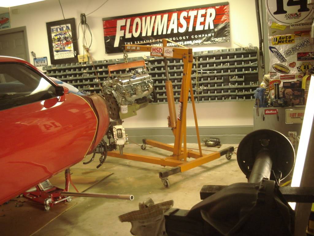
With the fluids taken care of (no need to drain oil in this case) I support the trans with a jack and hook up the engine hoist with the chains just snug so the engine and trans can't fall and then remove the bolts holding the engine and trans together, the bolts holding the flexplate to the torque convertor, and the trans crossmember bolts. A slight tweak with a prybar between engine and trans housing slides the trans back far enough to remove the engine. Then remove the engine mount bolts and out she comes!
Last edited by NOT A TA; 05-10-2014 at 05:49 PM.
11-22-2011 #40
Registered User
- Join Date
- Mar 2007
- Location
- Florida
- Posts
- 2,391
With the engine out I moved the trans forward to clear the crossmember, removed the torque convertor, and dropped the trans down and moved it out of the way. I've got a T-400 that will be replacing the T-350 and I'm giving the 350 to a bud who needs one for a late 2nd gen TA with a mild Pontiac 400 he's building for his wife. He's a hardcore Ford guy and it's killing him to build the TA she wants AHAHAHA. Wait till the wife feels the tires chirp when it hit's second with the shift kit and the stock stall convertor!
So engine and trans out with no big muss or fuss other than a couple little drips of trans fluid on the cardboard from removing the torque convertor.
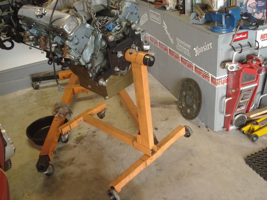
Once the trans was down and safely out of the way it was time to get the engine on a stand. For you guys reading to get tips, here's a few. Remember, engines are heavy. Keep yourself out of positions where if something goes wrong you could be be pinched against a solid object (including floor). Pick up all tools etc. and get them out of the way before putting the engine on a stand. Clean work area is a safer work area!
1. Don't forget to remove flexplate before putting an engine on a stand.
2. When choosing a stand for a big heavy engine with accessories like this one DO NOT use a stand with only one wheel in the front, they're more "tippy" and you'd be amazed how quick an engine can flip and crash (I've seen it happen). Use a stand with double front wheels for any big heavy engines.
3. Check the bolts you're going to use to bolt the engine to the stand (no, the bellhousing bolts will not work) to be sure the shank of the bolts will not protrude and bottom out on the block. Also be sure the bolt won't bottom out in the block before it's tight. Space the bolts with washers if necessary.
4. Bolt the stand adapter to the block while the engine is hanging with the bolts loose. Then center the part that slides into the engine stand. Tighten up all the bolts. DO NOT overtighten, nothing trying to pull the engine off the stand.
5. Pick up the stand itself, and slide it on the adapter. Insert the pin that keeps the engine from being able to rotate on the stand.
6. Gently lower with attached stand.
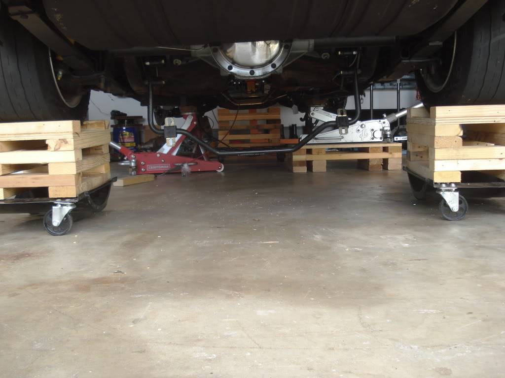
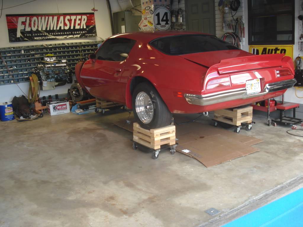
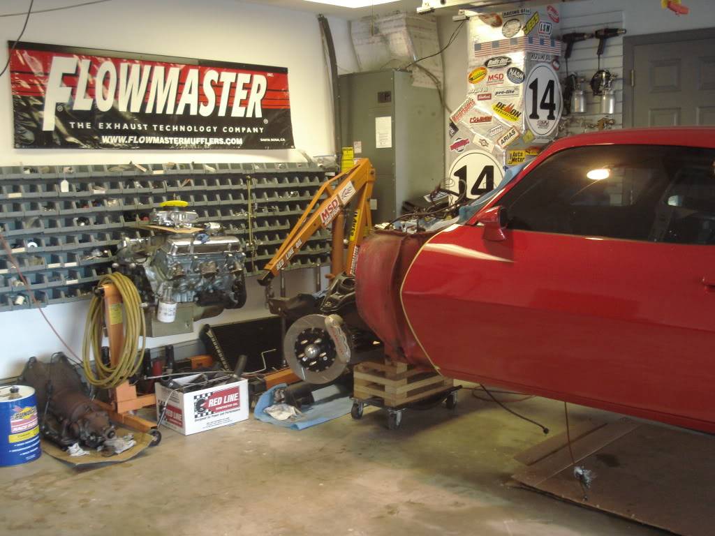
So with the engine and trans out and safe it was time to pick and move the car so I can get another one back in the garage also while I work on all the parts. I decided to try and combine two great ideas. Wheel cribs and wheel castors. It actually worked very well and is suprisingly stable.


 Reply With Quote