

Results 161 to 180 of 388
-
08-20-2013 #161

 Registered User
- Join Date
- Nov 2002
- Location
- state of confusion
- Posts
- 1,499

I've seen a sketch of a jig that would allow you to measure caster directly. IIRC, it registers off the ball joint studs - which has its own difficulties, including getting access to them without disturbing the wheels at all and ensuring that the jig is oriented specifically in a longitudinal plane (otherwise you'd be getting a mixed reading of cosine times caster and sine times SAI).
1/4" at 7' plus an assumed 6" for the steering arm length gives about an 0.042" difference if you were using dial indicators against the wheel flanges at 15" on center. You'll note that your data points do not lie in a straight line - this is to be expected. It's high, but not unexpected. I clearly remember having to saw away at the steering wheel of the Malibu to stay on line when encountering gentle pavement heaves in the middle of sweepers at only normal street driving speeds.
Norm'08 GT coupe, 5M, suspension unstockish (the occasional track toy)
'19 WRX, Turbo-H4/6M (the family sedan . . . seriously)
Gone but not forgotten dep't:
'01 Maxima 20AE 5M, '10 LGT 6M, '95 626, V6/5M; '79 Malibu, V8/4M-5M; '87 Maxima, V6/5M; '72 Pinto, I4/4M; '64 Dodge V8/3A
-
08-20-2013 #162 Registered User
- Join Date
- Aug 2012
- Location
- Peoria, AZ
- Posts
- 1,758
Thanks Norm, I knew I could count on someone to do the math for me. ;) I moved the data lines down myself to give me room to write the fender height measurements on the sheet, The dot on the paper stayed at about the same height as it moved across.
I didn't have my GoPro out in the shop last night, I'll do this exercise again later while running the camera to show actual movement.
I forgot I picked up a dial indicator at a swap meet a few months ago, maybe I'll use it on the wheel to see how much it is moving there.Lance
1985 Monte Carlo SS Street Car
08-20-2013 #163
Registered User
- Join Date
- Nov 2002
- Location
- state of confusion
- Posts
- 1,499
Double post, page didn't update properly for me.
Norm'08 GT coupe, 5M, suspension unstockish (the occasional track toy)
'19 WRX, Turbo-H4/6M (the family sedan . . . seriously)
Gone but not forgotten dep't:
'01 Maxima 20AE 5M, '10 LGT 6M, '95 626, V6/5M; '79 Malibu, V8/4M-5M; '87 Maxima, V6/5M; '72 Pinto, I4/4M; '64 Dodge V8/3A
08-20-2013 #164
Registered User
- Join Date
- Nov 2012
- Location
- Sacramento, CA
- Posts
- 1,918
Hey Lance,
You're doing a great job. I suspect you're learning a lot too & having a few "ah-ha" moments. Doing this "hand-on" is a great learning experience compared to talking about it or playing with computer programs.
You measured from the tie rod, which is "approximately" 6" behind the front of your tire. Therefore the math works out to approximately .090" toe change per 1/4" on your graph paper. So in 2" of dive (compression) your Monte is bumping out .180"
You & I are happy ... for now. I'll explain to everyone else why.
Everyone following along ...
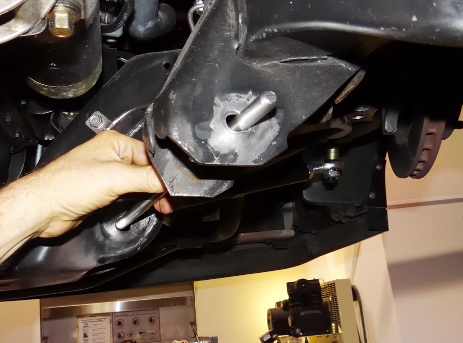
Lance installed the bump steer kit with the rod end as low as it would go on what is called the "bump steer stud" that bolts into the spindle in place of the tie rod. The lowest position provides maximum "bump out". We did this, so we could check to see if we would have enough adjustment with the bump steer kit we choose. Stock production cars typically "bump in" ... meaning the steering gains toe-in on suspension compression. They typically bump in ... a lot.
When you tilt the spindle back ... to add caster ... you're raising the steering arm ... which increases the "bump in" ...making it worse if you don't fix it. So I knew we'd need to move the tie rod pivot down away from the steering arm more than most to achieve "zero bump" because of the higher caster Lance is running.
Right now, the car has about 7.5° of caster ... and the steering "bumps out" .090" per inch of travel. We would like to increase the caster to 9.5° ... which will raise the steering arm up even more ... about .227" or close to 1/4". This will reduce this "bump-out". We need to make sure it doesn't turn back into "bump-in". Our goal is zero bump steer change from ride height, compressing 2" or lifting 1". We'll go past this to see when it changes. But all that really matters is the suspension travel you're actually using in track conditions.
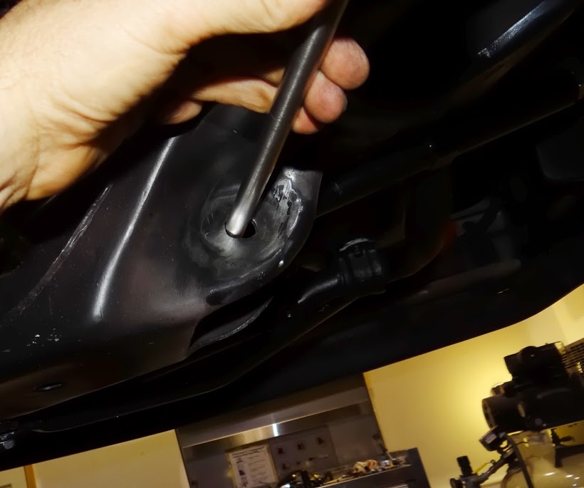
So Lance, lets do a brief "mock" bump-steer exercise to ensure we can get the bump steer to zero change through the travel area we care about. With no changes to the suspension ... take a small amount of shim from above the rod end & place it below the rod end ... raising the rod end up .... and re-run your laser test. For this exercise, converting the math is unnecessary. If you achieve zero bump steer on your graph paper ... 7' out ... you would have zero bump steer at the tire.
You don't need to futz with thin shims to get it to absolute zero at this point. We just need to see what will happen when you add caster & the steering arm raises .227". So one of your laser tests needs to be with the rod end up that amount. If your bump steer kit has a .100" shim & a .125" shim ... that is what you need to move from above the rod end to below it & test. If not, use a .200" shim or .250" shim to get us close.
I'd suggest doing this one shim at a time ... so you can see how this works, and within this range ... how much shim equals how much change ... I'd suggest you get there a shim at a time. Measure the shims each time & record it, so you know how much shim equals how much change ... and at what point does it go past zero bump & turn back into "bump in".
Post any questions if you're not clear.
08-20-2013 #165
Registered User
- Join Date
- Nov 2012
- Location
- Sacramento, CA
- Posts
- 1,918
 Originally Posted by Norm Peterson

How I did it came up with .045" roughly. But it doubles when measuring for toe-in or toe-out ... because you're measuring the difference in front of the tire ... .045" ... and at the rear of the tire ... another .045" ... to get to .090".
It could very easily be .042" +.042" = .084". I used 26" for tire diameter, but that was just a ball park too. I'm not worried about being super precise at this point, and I want to use methods most car guys are comfortable with.
08-20-2013 #166
Registered User
- Join Date
- Aug 2012
- Location
- Peoria, AZ
- Posts
- 1,758
Sounds good Ron, I can do that. I can do this on just one side right, no need to do the passenger side too since it appears it is moving the same amount?
Regarding the work...it's pretty interesting...to me anyway. Most of the people I talk to about what I'm doing think I'm bat crap crazy, but they just don't understand. I'm a problem solver by nature, and I like projects. Once I start on something, I dig in like a bulldog and try to not stop until it's done. Each step along the way where I'm successful eases my mind and refreshes me for the next step. Getting the right size drill rod and washers was taxing me, I get uncomfortable when things don't go as planned and am anxious to get the ship righted as soon as possible. My mind was eased when that all went to plan last night...finally...
Now I just have to get the thoughts of taking a carbide bit to my lower control arm mounting locations correctly out of my mind and eased...

 Lance
Lance
1985 Monte Carlo SS Street Car
08-20-2013 #167
Registered User
- Join Date
- Nov 2012
- Location
- Sacramento, CA
- Posts
- 1,918
As a veteran of the process of correcting and/or modifying the LCA pivot axis, I'm telling you if you take your time & follow the instructions I'm about to post, it will all be good. I'll get a detailed outline about LCA pivot axis problems, corrections and modifications later today. Originally Posted by SSLance
08-20-2013 #168
Registered User
- Join Date
- Nov 2012
- Location
- Sacramento, CA
- Posts
- 1,918
Correcting Lower Control Arm Geometry
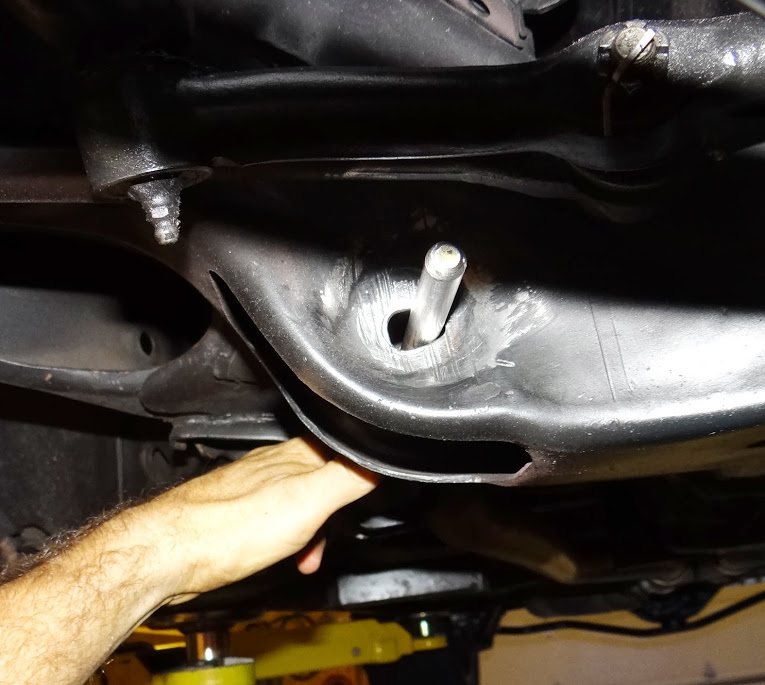
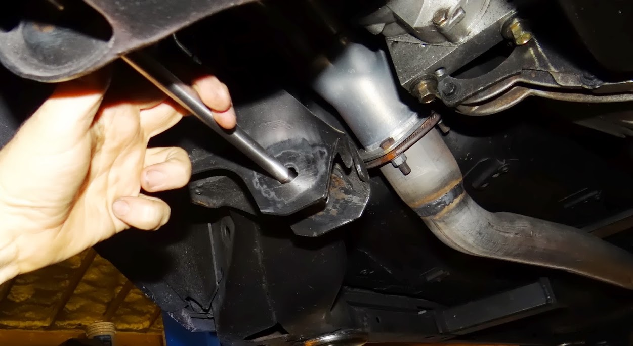
We all know there are factory tolerances in production cars. An area that most car guys dont think about are the actual frame mounts for the lower control arms (LCA). The area were talking about are the buckets or receivers in the front frame clip that the LCA bolts into. They have a hole on each side of the receiver for the bolt to pass through in two locations and two receivers so a total of 4 holes for each side.
If you draw an imaginary line through those 4 holes, that is the LCA pivot axis. Forget imaginary run a solid, straight rod through those four holes and you can see it, touch it & measure it. If your car uses ½ bolts, get ½ quality straight rod. If your car uses 12mm bolts for the LCA like Lances 85 Monte Carlo SS get 12mm rod.
In my experience the LCA pivot axis is off right out of the factory ... on most cars. They may get farther off if the car frame or clip had any tweaking from incidents.
That LCA pivot axis is important to the front suspension geometry in many ways. Very important in many ways and usually overlooked. The LCA pivot axis is probably off meaning not true & not the same from side to side in your car. It has a direct affect on the handling of your car. Lances car had one receiver bucket ¼ higher than the rest affecting anti-dive, caster gain & roll center migration. This changes where the instant center of the control arms intersect that forms what is called the swing arm..
If one side is off this makes the swing arm lengths different from side to side. That will place the roll center off to one side as opposed to being in the center where it belongs. This swing arm difference compounds when the car is driven on track & the body rolls in the corner. Lances front roll center was 9.3" to the left of center sitting statically in the parking lot. When he autocrosses it on LH corners, the RC moved, or migrated, to 18.7" left of center ... which contributes to a higher degree of body/chassis roll angle on LH corners compared to RH corners. You can read more detail about this in Post #93 of this thread.
All were really talking about are the 4 holes that locate the LCA. They are important but this area is basically pretty simple.
In my experience, I find these LCA mounting holes can be off in any of three ways.
1. Very common problem is all four holes simply dont line up meaning you have to force the second bolt in and the LCA has some degree of bind friction. If you were to run a correct size rod through all four holes often the holes dont line up. The rod has to be forced in, or wont go at all.
2. When you do run a rod through all four holes on each side for both LCAs the horizontal angles of the rod, which is equal to the LCA pivot axis often dont match. It is common for them to have differing horizontal angles, like Lances did.
3. When you do run a rod through all four holes on each side for both LCAs the angles of the rod in relation to the chassis centerline occasionally dont match. It is not uncommon for them to have differing angles relative to the chassis centerline. This affects lower ball joint location in the fenderwell, therefore tire & wheel location in the fenderwell and overall wheelbase.
Lets discuss in detail what each of these affect & what that means to the handling of the car.
-------------------------------------------------------------------------------
#1. If you cant run a truly straight steel rod through all four holes & rotate the rod smoothly with no friction & no bind how will the LCA rotate without friction and/or bind? It cant. If you have to force the second bolt in or bend the bushings in the LCA to get the second bolt to go in the LCA then the LCA has some degree of bind friction. If thats the case which is common the LCA doesnt move freely & easily. Some degree of force is required to move the LCA up & down.
This is bad. Way worse than the typical mechanic thinks it is for high performance & track driving.
That bind friction means the LCA doesnt respond to small degrees of force. This reduces the tires ability to follow small irregularities in the track surface. That means you have less grip with the front tires. This is not huge, but it is bad. Any reduction in front tire grip means your car is slower on track period. When races are won by seconds or less, .5 to 1% less front tire grip is a big deal.
That same bind friction also means the LCA doesnt respond as quickly to larger degrees of force. There is a bit of lag. Again, this is not huge, but it is bad. Any slowing of the suspension means the tire is not following the track as well as it should. This really shows up on 7-post shakers where were looking at percentage of tire contact. Not being able to keep the tire following the track surface equals a reduction in front tire grip. Your car will be slower on track. Every little bit of front tire grip matters.
You need to have your LCAs pivot freely, without bind & with minimal friction. This is an easy fix, that Ill outline later. When you have it right, the LCA should pivot super free.
-------------------------------------------------------------------------------
#2. When you run a rod through all four holes that mount the LCA that is the LCA pivot axis. If you put an angle finder on the very top or bottom of the rod (in between the two receiver buckets) and look at it from a side view that will give you the horizontal LCA pivot axis. Rarely are they 0.0°. The problem is less about what the angle is and more about the angle being different from side to side. If one side is 1.2ۜ° uphill to the front and the other side is 2.1° uphill to the front you will have several suspension geometry differences from side to side.
The horizontal LCA pivot axis affects:
Anti-dive
Caster gain
Swing arm length
Camber gain
Roll center location
Roll center migration during suspension travel
Holy crap. You dont want all of these things different from side to side on a street, road race or AutoX car. Yes, oval track race teams intentionally make them different from side to side, to help them achieve their specific goals turning left & only left.
Anti-Dive & Pro-Dive primer:
The net degree of anti-dive or pro-dive the front control arm assembly has, is completely determined by the instant center formed by the UCA & LCA horizontal angles (side view). Both UCA & LCA horizontal pivot angles define this not just one. So the LCA pivot angle is simply affecting the total.
Simply put, if the instant center is behind the front axle centerline, the front control arm assembly has anti-dive. If it is in front, it has pro-dive. The longer the distance from the axle CL to the instant center the less degree. The shorter the distance to the instant center, the higher the degree.
The LCA pivot axis running downhill to the front adds anti-dive to the front control arm assembly. Uphill adds pro-dive the opposite of anti-dive. Said another way, if the LCA is running uphill to the front it simply reduces the degree of anti-dive.
Anti-dive adds caster as the suspension compresses. This is known as caster gain. Pro-dive reduces caster as the suspension compresses. This is known as caster loss.
You sure dont want these different from side to side. Having less anti-dive on one side of the car will make that corner compress the suspension quicker & end up with less caster in dive. Having more anti-dive on one side of the car will make that corner compress the suspension slower & end up with more caster in dive. This means the car will have more roll angle turning one direction and less roll angle turning the other. And youll have caster split (difference in caster from side to side) making the car turn easier to the side with more caster & harder the other way.
Moving on to other problems
With the two front control arm assemblies having different geometry in additional to anti-dive & caster gain differences you also end up with different swing arm lengths side to side meaning youll have different camber gain on each side. The roll center location wont start in the center and it will migrate to different points during suspension travel & body roll.
To summarize the car will not turn the same one direction as the other. As much as the final numbers matter being the same from side-to-side is just as important. So you need to get the horizontal LCA pivot axis the same from side to side.
------------------------------------------------------------------------------------------
#3. Most everyone has seen factory LCAs and know they are longer on one end & have the pivot axis at an angle to the chassis centerline.
If you were to look from a top or bottom view of the chassis and you have a rod through all four holes on each side for both LCAs the angles of the LCA pivot axis in relation to the chassis centerline occasionally dont match side to side. They are typically around 14°. But if one side is 14.1° & the other side is 13.3° you may want to true that up. Why? what does it affect?
That angle plays a role in the location of the lower ball joint, therefore the steering axis of that suspension system. In my experience with factory clips, this can vary just as easily as the other angles being off from side-to-side. If one side is angled less, that moves the lower ball joint and spindle, wheel, tire, etc rearward in the fenderwell shortening the wheelbase on that side of the car. (Assuming the rear axle is true in the car.)
Obviously, if the LCA on one side is angled more, that moves the lower ball joint and spindle, wheel, tire, etc forward in the fenderwell lengthening the wheelbase on that side of the car. (Assuming the rear axle is true in the car.) Regardless of how you view it if one is back or one is forward if the front axle/spindle centerlines are not even you will have handling differences.
What does this affect?
When the wheelbase of the car is different side to side and the differences are in the front & the rear axle is square the car will compress the suspension farther on the front corner with the shorter wheelbase.
Example:
With rear axle square in car and the wheelbase is 108-1/4 on the left & 107-7/8 on the right the car will be looser on LH turns & tighter on RH turns. Yup might want to square this up.
--------------------------------------------------------------------------------------------------
Ill be back on today with a post on how to measure, how to correct & how to improve LCA geometry.
08-20-2013 #169
Registered User
- Join Date
- Aug 2012
- Location
- Peoria, AZ
- Posts
- 1,758
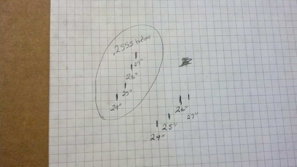
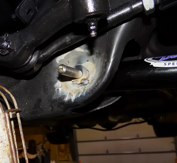
Little more playing around with the bump steer kit.
With 0.2555 spacer below the rod end bump steer out 7 feet in front of the tire was as follows
.500" out at 24" fender height
.250" out at 25" fender height
.000" out at 26" fender height
.187" in at 27" fender height
With 0.4710 spacer below the rod end bump steer out a 7 feet in front of the tire was
.250" out at 24" fender height
.000" out at 25" fender height
.000" out at 26" fender height
.000" out at 27" fender height
.187" out at 28" fender height
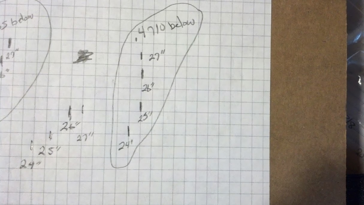
Like Ron said, we are still going to add another caster which will raise the steering arm up, but it looks like we should be able to fine tune the bump steer pretty well with this kit (to my untrained eye anyway).Lance
1985 Monte Carlo SS Street Car
08-20-2013 #170 Registered User
- Join Date
- Apr 2009
- Location
- san diego
- Posts
- 5,102
If its a front steer it looks like the tie rod is too long. Any way to adjust the inner pivots easily?
My build thread: https://www.pro-touring.com/showthre...ing&highlight=
The mustang build thread: https://www.pro-touring.com/showthre...el)&highlight=
08-20-2013 #171
Registered User
- Join Date
- Nov 2012
- Location
- Sacramento, CA
- Posts
- 1,918
Measuring, Correcting & Improving Lower Control Arm Geometry
We have three areas to work on:
1. LCA rotation
2. Horizontal LCA pivot axis
3. LCA pivot axis angle in relation to the chassis centerline
We have three possible goals:
1. Measure
2. Correct
3. Possible relocation for improvement
I am going to outline how to measure each of the three areas how to correct all three and potentially change angles for geometry improvement. Before you get started, you get clear on your goals. Are you looking to true everything up for matching suspension geometry & even handing characteristics when cornering? Or are you looking to change geometry?
When Lance was measuring all the suspension points so I could calculate his roll center, camber gain, etc he ran across one of the receiver buckets ¼ higher than the rest. I discussed what problems that causes and showed him in the roll center graphs and of course he wanted to correct it.
On the tuning front
Lance already has the adjustable DSE UCAs that added some caster, but he was maxed out at 5.7° currently. Lance wanted to make his car capable of up to 9.5° caster for AutoX competition. We planned to get this additional 4° through the LCA which means youre moving the lower ball joint forward. The calculations showed he needed to move the LBJ forward .800+ to achieve this. I calculated that would move his spindle axis, tire & wheel forward about 9/16. Since his tire & wheels were already located more than 9/16 behind the centerline of the fenderwell, this would be a double win.
The DSE lower control arms Lance chose are designed to move the LBJ forward by .400. So we needed another .400+. Given that Lance already needed to correct his LCA mounting holes making the decision to get the additional .400+ of LBJ forward movement by moving the LCA axis made the decision easier. Once Lance started this process, he found out his lower control arms had bind friction, as outlined in problem #1 in the previous post.
So Lances goals are:
1. Eliminate any LCA pivot bind friction
2. True up the horizontal LCA pivot axis if needed
3. Gain caster by moving the LBJ forward.
----------------------------------------------------------------------------------------------------------------
Step-by-Step Plan:
Please read this thoroughly before starting, because it may prepare to do some things before you get started.
Parts & materials needed:
Two 16-18 pieces of truly straight, solid rod of the same diameter as your LCA bolts
Hardened Machined Washers 3/16+ Thick
Machined washers can not be sloppy on the bolts
LCA Bolts ½ Longer to account for the thick washers
New lock nuts
Tools needed:
Tape measures
Level
Accurate digital angle finder/inclimeter
Removable masking tape & sharpie
Jack, jack stands, stand shims
Die grinder with small round burr
Round file
Sander or wire wheel to remove paint
Welder
Tip #1: Leave the die grinder in the tool box until all measurements are captured & were clear on all the goals.
Tip #2: Whether you use a lift, or jack stands, the closer you have the car to ride height angle (rake) & level side-to-side the easier it is to keep angles clear in your head. If you cant do that. Figure out what the rake of the car is on the ground and check it in the air and write down the difference & direction so you can refer back to it when your mind is cluttered with angles.
Tip #3: Whenever you measure angles always write them down with a note next to them saying raw number. This means it was taken with the car in the air. Then also write in your notes and add or subtract your correction number to know the corrected angle if the car was at its normal rake angle for ride height. I cant stress this enough to write the word raw or corrected next to the appropriate numbers. This will keep your head clear & reduce the required drinking later.
--------------------------------------------------------------------------------------------------------------------
Step #1
Run the rod through all four LCA mounting holes on each side of the car. If you can not easily slide the rod through the 4th hole figure out which hole or holes you can modify the least to get it to slide through. At this point, if it is snug, thats not a problem. But if it requires flexing the rod to go in, dont do it. It will throw your measurements off. If you need to remove very much material get clear on which direction you move the LCA for your goals & remove material in the direction that helps your cause and allows the rod to slide in easily.
Tip: I have found taking a little off opposite sides fo the two inners holes to be easiest.
Step #2
Install the LCAs with the rods instead of bolts & make sure they rotate freely. Using adjustable jack stands, shims, etc support the outer end of each LCA to mock up ride height. If the car is in the air, or on a lift, you can simply put the LCAs at the same angle (front view) that they were on the car at ride height on the ground.
--------------------------------------------------------------------------------------------------------------------
Step #3
Using a digital angle finder/inclimeter on the very top or bottom of the rods, capture & record the exact angle of each horizontal LCA pivot axis. Figure out the difference and decide if youre going to match them by modifying just one side or modify each side a little to meet in the middle or modify both sides to achieve a target geometry you want.
Reminder: Convert the angle degrees to be corrected with the car at the normal rake angle for ride height.
If the two sides are close say the corrected left number is 0.8° uphill in front & the corrected right number is 1.1° uphill in the front you may decide to modify just one side to match them up. Which one you choose to keep depends on your geometry goals. I usually want them level to the ground or running slightly downhill to the front so we get more anti-dive & caster gain, as outlined in the previous post. So I would suggest the left 0.8° as your target & match the right side to it.
Frankly, if it was a race car or hardcore track car, 0.8° uphill wouldnt make me happy. That reduces the total anti-dive & caster gain. For my cars, I would be adjusting both LCAs to achieve a level horizontal LCA pivot axis at minimum or I may even get it running downhill going forward to add to the total anti-dive & caster gain. In my NASCAR Modifeds, whether we used Impala or Chevelle clips, we ran the horizontal LCA pivot axis at 3.0° downhill going forward. Thats not a magic number for all set-ups, just what worked well with our high travel Mods.
Tuning Tip: If you know youre going to need all the caster you can get or youre having a hard time achieving your total caster goal now is the time to add some caster gain. Again, tipping the horizontal LCA pivot axis downhill going forward adds anti-dive & caster gain.
--------------------------------------------------------------------------------------------------------------------
Step #4
With the LCAs mocked up at ride height (or ride height angle) you need to measure what I call the X & Y coordinates of the lower ball joints. Find & mark a spot on the frame to measure out from the frame to the center of the LBJ and write it down. This is X. It is important that your X measurements be a true 90° or as close as you can humanly get it and/or exactly in the same spot from the frame on each side of the car.
Find & mark a spot on the frame or firewall to measure forward to the center of the LBJ and write it down. This is Y. It is important that your Y measurements be truly parallel with the car or as close as you can humanly get it and/or exactly in the same spot from the frame/firewall on each side of the car. Now do the other side & compare the numbers.
Im sure this goes without saying except Im going to say it. You want to be as accurate as you can be. Some tips are:
Get a helper.
Measure the same way all the time.
Make sure the tape is level, square, etc.
Dont run the tape at an angle. Use a level or square.
Have only one person read the tape.
Take your time & do it with care. Rushing leads to errors.
Double & triple check your numbers.
Dont be surprised if the numbers from side to side are a little different. Be surprised if theyre the same.
Initially just compare the left & right side X numbers then just compare the left & right side Y numbers. But when you decide what youre doing think of the combined direction you need to move the LCA pivot axis to achieve both.
If the two sides are close on their X numbers say the left side ball joint is 12-1/8 out from the frame & the right side is 12-3/16 you may decide to modify just one side to match them up. If on the other hand, if the X numbers vary significantly the left side ball joint is 11-3/4 out from the frame & the right side is 12-3/16 you may still decide to modify just one side to match them up or you may decide to create a target number in the middle and move them both to that target number in the middle. Which route you choose may depend on your track width or clearance goals.
If the two sides are close on their Y numbers say the left side ball joint is 24-1/8 ahead of your measuring point and the right side is 24-1/4 you may decide to modify just one side to match them up. If on the other hand, if the Y numbers vary significantly say the left side ball joint is 24-1/8 ahead of your measuring point and the right side is 24-7/8 you may still decide to modify just one side to match them up or you may decide to create a target number in the middle and move them both to that target number in the middle. Which route you choose may depend on your caster goals or location of the axle centerline, tire & wheel in the fenderwell.
Regardless of your geometry goals, the important thing is to get both sides the same-same-same in every aspect.
Tuning Tip: If you know youre going to need more caster or you need a little more or less front track width now is the time to get it. If this is a race car or hardcore PT track car, I would take this opportunity to push the ball joints out for a wider front track width (providing you have fender clearance) and to move the ball joints forward enough to achieve the maximum caster you could dream of running. I make all my race cars have caster capability of 2.0°+ more than the KPI degree angle just in case I ever need it.
--------------------------------------------------------------------------------------------------------------------
Step #5: The Ah-ha Stage!
Now you know where you are with all your measurements. Work out the math & decide your target numbers for each of the three items:
1. Target horizontal LCA pivot axis angle in degrees.
2. Target LBJ X location in inches.
3. Target LBJ Y location in inches.
With these numbers:
Decide which LCA pivot ends youre deciding to move and which directions you need to move them and combine the directions & amounts. If you need to move the front of the left LCA down 1/8 & inward 1/8 you could go down & in at a 45° angle ..175 (close to 3/16). Otherwise, if you grind down, then over, youre removing unneeded material.
Most machined washers for this application provide a band around the bolt. Measure yours to see how wide that band is. If its 5/16 I suggest not grinding out more than 5/16 with the hole in any one direction. If you have more to remove than the band width of the washer it is ideal to split the amount of material removed from both receiver buckets versus taking it all out of one.
For example: If you need to move the front of the left LCA down 1/4 & inward 1/4 you could go down & in at a 45° angle .350 (close to 3/8) thats wider than the band of your hardened washer. Instead of doing that, I suggest you go down & in at a 45° angle .175 (close to 3/16) on the front of the left LCA and go up & out at a 45° angle .175 (close to 3/16) on the rear of the left LCA. Make sense?
If you have a small to moderate amount to remove achieving it all in one receiver bucket is fine, as long as you dont enlarge the holes so big the washer cant cover them. Lastly, if you can achieve the same goal by working either the front or rear receiver bucket the rear one without the crossmember is often easier to work with. Just sayin
Washer Tip:
If you find you need to grind farther than the range were covering here, you may want to explore larger outer diameter washers. It is key to have the washers thicker than the receiver bucket material by at least 50%. I use 3/16 & ¼ thick washers with great success. Also, I have had grade 5 & grade 8 stamped washers wear the holes out of round over time. I have never had a problem with hardened washers changing shape.
Important: If youre going to fully weld the receiver buckets to the frame where there are weld gaps now is the time before you start grinding on the holes. I suggest this. But if you try to do it at the end, it will cause bind issues.
--------------------------------------------------------------------------------------------------------------------
Step #6: Now the grinding begins.
Tools needed:
Die grinder with small round burr. I prefer a ¼ burr.
Round file
Sander or wire wheel to remove paint
Welder
Tape measures
Level
Accurate digital angle finder/inclimeter
This is no big job. And it is not super sensitive either. You will end up grinding the holes slightly bigger than they need to be because youre not going to use the holes to support the LCA bolts anyway. That is what the 3/16-1/4 thick, hardened, machine washers are for.
All were really talking about here is enlarging these 8 holes just enough to achieve your target LCA pivot angle & ball joint placement goals. This is important but the process is basically pretty simple. Once you know the direction & estimated amount of material to remove, get to grinding & filing.
Here are my tips:
Again, dont be in a hurry. That leads to mistakes and/or too much material removed.
You dont need the LCA in place for the horizontal LCA pivot axis angle but you do for the ball joint measurements.
You will need to remove & reinstall the LCA & rod often. Out to grind back in to measure.
Dont get lazy and grind a ton without checking it.
A helper assisting makes the day go a lot easier.
Deburring the inside of the receiver buckets helps the LCA to go back in easier.
I prefer to grind the hole on the inner side of the receiver bucket first as needed to achieve the desired angle then simply slide the rod through and mark the other side of the receiver bucket with a sharpie around the rod to show me where & how much to grind.
It is ideal to remove a modest amount of material from both receiver buckets than to just one.
If you are removing the majority of material from just one receiver bucket you may find you need to grind a little here & there on the other receiver bucket to get the rod & LCA to move where you need it to.
When in doubt take it out & check.
I cant say this enough. Whatever numbers youve decided on you will want make both sides identical.
--------------------------------------------------------------------------------------------------------------------
Step #7: Targets Acquired
When you achieve the:
Target horizontal LCA pivot axis angle in degrees.
Target LBJ X location in inches.
Target LBJ Y location in inches.
Deburr the inside & outside of the receiver buckets. Then use a sander or wire wheel to remove the paint from all surfaces that will get welded. I do the insides too, just so I dont have to breathe paint fumes in while Im welding.
When you put the LCA & rod back together this final time before welding install all the washers as you go. Then travel the LCAs through their motion range to ensure there is absolute no bind or friction. If there is any, fix it now.
Double & triple check your measurements. When youre confident they are right, its time to weld the washers in place.
--------------------------------------------------------------------------------------------------------------------
Step 8: Welding
With the LCA & rod in place tack weld the thick, hardened, machine washers on 3-4 corners of the washer. Do all 4 washers then travel the LCAs through their motion range again to ensure there is absolute no bind or friction. If there is any, fix it now.
If there is no bind or friction:
1. Check your measurements again.
2. Remove the LCA & rod
3. Reinstall the rod
4. Weld up the washers.
Of course youre going to travel the LCAs through their motion range again to ensure there is absolute no bind or friction. If there is any, fix it with a small hand file.
--------------------------------------------------------------------------------------------------------------------
Youre done with the mods. You can now repaint spots, & reassemble the suspension.
Final Tip: Do NOT crank down on the LCA bolts & nuts. Tighten them just enough to so the bolt doesnt spin. The lock nut will hold the bolt in. But if you crush the receiver buckets you will create bind & friction in the LCA.
.
08-21-2013 #172
Registered User
- Join Date
- Aug 2012
- Location
- Peoria, AZ
- Posts
- 1,758
Alright!!! Easy peasy sounds like...

Actually that all seems pretty much like I envisioned it would go. My main concern given my setup is how am I going to get the frame square and level and the LCAs at ride height repeatedly for accurate measuring. I think I've come up with a plan though, let me know what you think of this.
I'll use the 2 post lift under the frame rails in the center of the car, they are leveled up front to back and side to side now (I've already checked). I've also currently got 10.5" stands set under each tire. My thought was to take some 4x4 posts that I have leftover from a project and cut them to my ride height length at the front of the frame rails (taken when on tires on the drive on lift) plus 10.5" and set them upright under the front frame horns and set the car down on them. This way the 4x4s would be holding the front section of the frame at ride height while the lift is holding the rest of the car at ride height and the wheels would be on the 10.5" stands under them. Ride height before was 25 1/4" at the fender and we are shooting for it to be closer to 26" so maybe I need to add 3/4s" to the 4x4s to achieve the frame height I'm looking for.
The car wouldn't be sitting on the 4x4s for support, the lift would still be supporting the main weight of the car...they would just be holding the front clip up from flexing down under the weight of the hanging engine. I guess ultimately a set of extra tall jack stands would be ideal for this and I might explore that angle today as well. They might not be as easily set to an exact height though.
My other question is whether or not to leave the lower ball joint hooked to the spindle during all of this or not? It would be a lot easier to put the LCA in and out of the frame buckets if it was loose, but it would be a lot easier to make sure it is all at ride height each time if it was hooked to the LBJ and the tire was on the stand.
I have time scheduled tonight to get after this...wish me luck!!
Lance
1985 Monte Carlo SS Street Car
08-21-2013 #173
Registered User
- Join Date
- Nov 2012
- Location
- Sacramento, CA
- Posts
- 1,918
Originally Posted by SSLance
Your message reads as if you're using techniques to accurately recreate ride height & measure suspension points ... like you did when measuring your front suspension geometry. That's not necessary here. It doesn't need to be that complicated. Keep it simple.
You got this Lance!Last edited by Ron Sutton; 08-21-2013 at 07:10 AM.
08-21-2013 #174
Registered User
- Join Date
- Aug 2012
- Location
- Peoria, AZ
- Posts
- 1,758
Alright, that helps... I can lock the lift and leave it set. I have one tall screw jack I can use to hold the LCA in place. I can probably use a floor jack and a 2x4 for the other side.
I'll just have to find an easy spot to measure the LCA against the frame at ride height so I can reproduce that LCA angle with the car up in the air.
Maybe I'll take those 24" jack stands I bought this morning back to harbor freight and pick up another screw jack...Lance
1985 Monte Carlo SS Street Car
08-21-2013 #175
Registered User
- Join Date
- Aug 2012
- Location
- Peoria, AZ
- Posts
- 1,758
I've got an idea...how about I just get a strong piece of wire (or plumbers tape maybe) and hook it in the sway bar mounting hole on the LCA and somewhere on the frame when the car is sitting at ride height. Then every time I put the LCA in with the car in the air, just hook that strap or wire back up and it'll hang the LCA in the exact same spot every time?
Lance
1985 Monte Carlo SS Street Car
08-21-2013 #176
Registered User
- Join Date
- Nov 2012
- Location
- Sacramento, CA
- Posts
- 1,918
That may work. I'm more a fan of something solid under the end. But that's your call & I'll let you figure that stuff out. Originally Posted by SSLance
Post pics when you're done & let me know if you have questions along the way.
08-21-2013 #177
Registered User
- Join Date
- Aug 2012
- Location
- Peoria, AZ
- Posts
- 1,758
Heck, if I can tie the sway bar up somehow, I can use the actual sway bar attaching links...just slide the bolt in the hole on the LCA each time.
This might even help more to keep the sides even if I can get the links both the same length.
I've looked for another screw jack locally and that isn't happening, so I need to figure another way to hold both LCAs up.Lance
1985 Monte Carlo SS Street Car
08-24-2013 #178
Registered User
- Join Date
- Aug 2012
- Location
- Peoria, AZ
- Posts
- 1,758
Originally Posted by Ron Sutton
I'm freaking physically and mentally wore out...
It all went pretty well though. Didn't set anything on fire and met almost all of the laid out goals. Please don't give me too much grief about my welds, I was much more concerned about making sure they were burnt in well than making them pretty. Plus I don't have near as much proper welding attire as I should have, especially for welding above my head. If one could do this with a stripped down frame without tie rods and other various parts in the way, it would be much easier to get the correct angle on the welding wire to pretty up the beads.Lance
1985 Monte Carlo SS Street Car
08-24-2013 #179
Registered User
- Join Date
- Nov 2012
- Location
- Sacramento, CA
- Posts
- 1,918
Originally Posted by SSLance
Haha. You did great.
When you "recover" ... post the specs & measurements of what you did ... and why ... so everyone following along can learn.
08-25-2013 #180
Registered User
- Join Date
- Aug 2012
- Location
- Peoria, AZ
- Posts
- 1,758
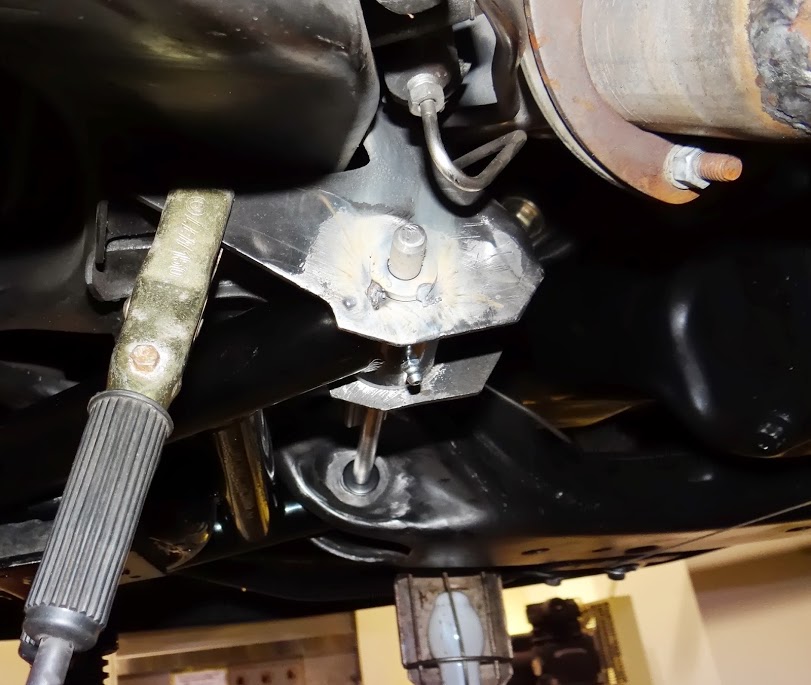
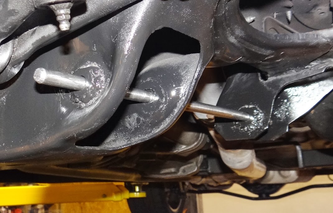
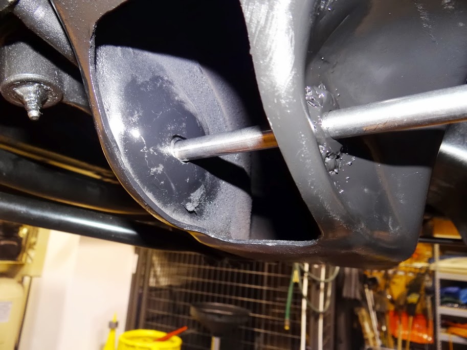
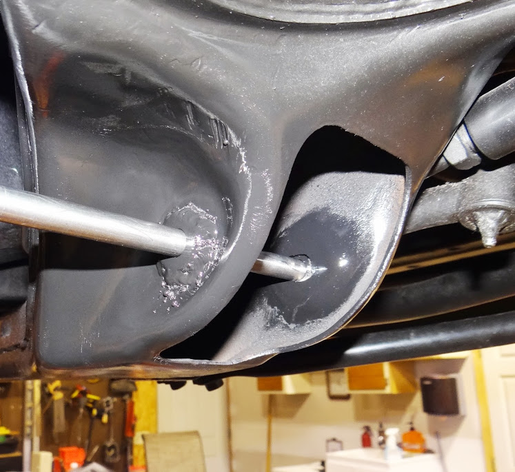
The hole movement goal was two or three fold... First the passenger front bucket holes had to go down to get the pivot angle the same as the driver side. Then the back bucket's holes on each side went out and the front bucket's holes on each side went in with the goal being to push the lower ball joint forward 0.400" than it was before while maintaining the exact same distance to the center of the frame.
We ground out the holes using a carbide bit on an angle grinder. Grind a bit, measure...grind, measure, grind measure...until we had the rods on both sides where we thought they needed to be. On several of the holes we could see the gap of the original hole past the edge of the washer. I was a bit unsure if I'd be able to fill that gap successfully with my limited welding skills so we stopped. At this point part of me was wanting to go all out and really move the holes further to gain every bit of potential caster, but my cautious side didn't want to create more problems with trying to get the washers welded in solid.
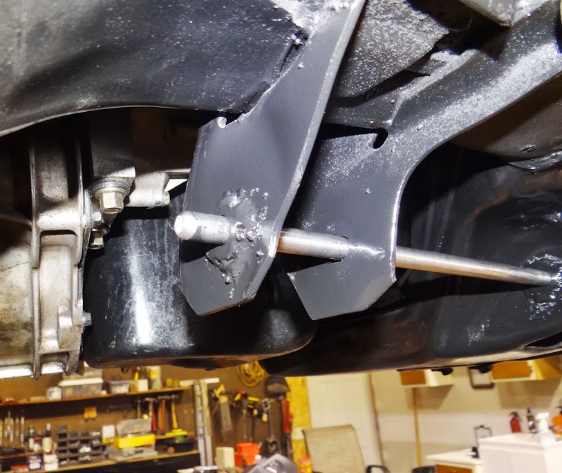
Then it was time to weld. We did the outer two washers first to get the rod set in place. Tacked them in, removed the rod, welded the washers solid, reamed the washers out a bit as they closed up and the rod wouldn't go back in...then put the rod back in place, tacked the inner two washers in place, removed the rod, welded the washers in, then opened them up so the rod would go back through all four washers tightly, but would still spin. Spatter would get on the rod when tacking which made it difficult to remove the rod each time because the washer to rod clearance was so tight. We found we had to file or grind the spatter off before removing the rod or risk breaking the tack welds on the washers driving the rods back out.
Hind sight, it wasn't that difficult to fill the gaps...I probably could have moved the holes a bit further and bridged that gap...but I just wasn't sure of that at the time. I was most concerned about blowing through the somewhat thin frame with the welder, but honestly, that never even came close to happening.
It was a long tedious process. We achieved most of the goals set out for us. We did the driver side first as the holes just needed to go sideways, not up and down. On the passenger side, we were tired, punchy, and needed to get it done as it was getting late and we just couldn't quite get the rod where we had the wheel base number AND the pivot angle number we were looking for. I made the call to get the pivot angle set to match the driver side but the ball joint ended up about 1/8" back from where the driver side is and the center out measurement is dead on. 2 out of 3 ain't bad I guess. We were tacking the washers in place when we discovered we couldn't quite get the rod exactly where we wanted it to be. We would have had to step back and go back to grinding some more to get it there and there wasn't enough time or motivation left to get that done at that point.
Hopefully we got it good enough and the UCA adjustments can mask the little bit of wheelbase difference. It has to be a BUNCH better than it was before as the pass side LBJ was a 1/2" in and a 1/4" back I think as well as the pivot angle being .4 degrees different than the driver side.Lance
1985 Monte Carlo SS Street Car

 Reply With Quote


