

Results 81 to 100 of 388
-
07-02-2013 #81
 Registered User
- Join Date
- Nov 2012
- Location
- Sacramento, CA
- Posts
- 1,918
 Cool. if you have questions, just ask.
 Originally Posted by SSLance

-
07-05-2013 #82
Registered User
- Join Date
- Nov 2012
- Location
- Sacramento, CA
- Posts
- 1,918
Hey Guys,
I'm on the Forum today for a few more hours ... then I'll be gone for a week.
I'm meeting up with my friend Neil Porter at Sears Point where he's running 2 formula cars in SCCA racing.
Then I'm camping with my girls the rest of the week.
I'll be back online late Thursday (7/11) or Friday morning (7/18).
07-11-2013 #83 Registered User
- Join Date
- Aug 2012
- Location
- Peoria, AZ
- Posts
- 1,758
Well I think I have completed the measuring of all of the pivot points. What an interesting challenge. I learned a lot about my suspension geometry during the process even without the data back from Ron. There is no doubt in my mind now that the 28 year old rubber bushings in my passenger side lower control arm are compromised and the arm is now out of spec (which is probably a factor in my excessive tire wear on that side as well).
I've sent all of my measurements to Ron which I'm sure he'll compile into his spreadsheets when he gets back into town. Can't wait to see what he comes up with once he reviews the data I have given him.
Stay tuned...Lance
1985 Monte Carlo SS Street Car
07-11-2013 #84
Registered User
- Join Date
- Aug 2012
- Location
- Peoria, AZ
- Posts
- 1,758
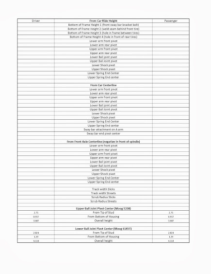
Here's how I went about accomplishing this exercise...first I had to create a worksheet to help me keep track of all of the measurements as I made them.
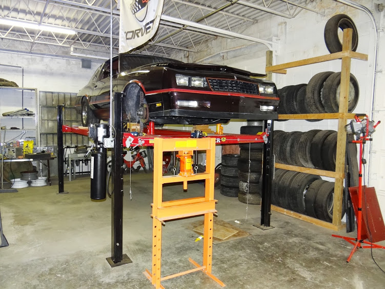
Then I set the car on a level drive on lift in simulated race prep mode...I even put (1) BBC head on the floor in front of the driver's seat and (2) SBC heads behind the front seat to simulate driver's weight in the car. I then made a careful measurement of the spindle heights and removed the front tires and set bottle jacks under the A-Arms as close to the ball joints as I could get them and adjusted the screws in the bottle jacks to get the spindle heights at exactly the same height as they were with the front tires on. This allowed me much more room to make the measurements needed.
Here is the car on the lift with everything I used during the process set up and ready to go
I needed to have a secure square stand for a laser level away from the car at different times and the shop press worked perfectly for this. Notice there is a laser level on the press pointed at the upper ball joint in this picture.
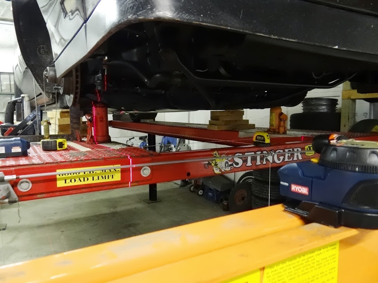
I also used a laser level to light up the string running down the whole center of the car and another to light up the string exactly 10" in front of the spindle centerline.
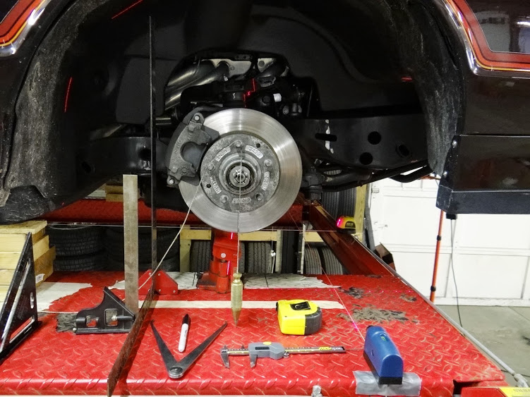
The framing squares and the magnets holding them in place were used in conjunction with the three laser levels, plumb bob, tape measure, digital caliper and verneer caliper to measure and record all of the pivot points from the three reference points of the center of the car, center of the spindle, and ride height, over 80 measurements in total including the track width and scrub radius measurements.
With a good friend's help, it took about a half day on Saturday, then a couple hours a night for 3 week nights to complete the process. I'm certain we could do it faster the next time given the tricks we learned doing this our first time.
But anyway, hopefully this shows the rest of you a bit more about what we had to go through to come up with all of the measurements that Ron is going to put to use to help me figure out a solution to my woes.Lance
1985 Monte Carlo SS Street Car
07-12-2013 #85 Registered User
- Join Date
- Nov 2002
- Location
- state of confusion
- Posts
- 1,499
I know I'm late here, but it's probably better to think of camber gain as a continuous curve over the entire range of suspension travel. It is not a constant value, although over short amounts of travel it won't vary a whole lot. This can be plotted in Excel once you generate a table of where the suspension pivots are located at various ride heights (I've got a 2-D model for the Malibu I used to have, and FWIW that car had ~640# front springs, ~165 rear springs, Bilsteins, F41 bars, and a little over -2.5° camber when autocrossed. Around +3° caster - it's been a few years so I don't remember it any closer than that). Originally Posted by SSLance
Camber gained as a function of the angle you steer the wheels and caster & SAI is a separate animal.
Norm'08 GT coupe, 5M, suspension unstockish (the occasional track toy)
'19 WRX, Turbo-H4/6M (the family sedan . . . seriously)
Gone but not forgotten dep't:
'01 Maxima 20AE 5M, '10 LGT 6M, '95 626, V6/5M; '79 Malibu, V8/4M-5M; '87 Maxima, V6/5M; '72 Pinto, I4/4M; '64 Dodge V8/3A
07-12-2013 #86
Registered User
- Join Date
- Aug 2012
- Location
- Peoria, AZ
- Posts
- 1,758
Hey Norm, good to see you in here.
For those that don't know, Norm helped me tremendously last season over on the Monte board when I was first trying to figure out how to autocross my car.Lance
1985 Monte Carlo SS Street Car
07-13-2013 #87
Registered User
- Join Date
- Aug 2012
- Location
- Peoria, AZ
- Posts
- 1,758
Hey Ron,
When you get a chance, will you explain Roll Center in layman's terms please? In a general sense, how is a car's Roll Center calculated and how is this Roll Center used when tuning a front or rear suspension?
I hear or read of Roll Center referred to often in suspension discussions and I kind have a handle on it, I think...but with my new found clearer understanding of suspension geometry and your unique way of making details simple to understand, it couldn't hurt to go through this part of it one more time...for me and others as well.
Thanks,
LanceLance
1985 Monte Carlo SS Street Car
07-13-2013 #88
Registered User
- Join Date
- Nov 2012
- Location
- Sacramento, CA
- Posts
- 1,918
Oh sure Lance, Originally Posted by SSLance
I'll get right on that after I create peace in the Middle East.


-----------------------------------------------------------------------------------
OK, seriously, I'm working on it now.
07-13-2013 #89
Registered User
- Join Date
- Nov 2012
- Location
- Sacramento, CA
- Posts
- 1,918
Hey Lance ... I wasn't able to create peace in the Middle East ... but I did write up some Roll Center info.
This may be my longest post yet ... and that's saying something.
Ill be very basic for any readers following along that are completely new to this & apologize in advance for boring the veterans that already have knowledge of this. Cars have two roll centers one as part of the front suspension & one as part of the rear suspension. Ill first explain what role they play in the handling of a car then how to calculate them and finally how to tune with them.
Think of the front & rear roll centers as pivot points. When the car experiences body roll during cornering everything above that pivot point rotates towards the outside of the corner and everything below the pivot point rotates the opposite direction, towards the inside of the corner. Because the front & rear roll centers are often at different heights, the car rolls on different pivot points front & rear typically higher in the rear & lower in the front.
If you were to draw a line parallel down the middle of the car connecting the two roll centers this is called the roll axis that line would represent the pivot angle the car rolls on again typically higher in the rear & lower in the front.
When a car is cornering the forces that act on the car to make it roll act upon the cars Center of Gravity (CG). With typical production cars & most race cars, the CG is above the roll center acting like a lever. The distance between the height of the CG & the height of each Roll Center is called the Moment Arm. Think of it a lever. The farther apart the CG & roll center are the more leverage the CG has over the roll center to make the car roll. Excessive chassis roll angle is your enemy, because it is over working the outside tires & under utilizing the inside tires.
Some people like to look at the car as a unit. I look at it as two halves. Here are some examples using a typical 3500# Pro Touring Car with 53% front weight to provide more clarity:
If the CG is 20 high and the front roll center is 2 below ground the car has 53% of the 3500# weight with 22 of leverage to roll the front of the car.
If the CG is 20 high and the rear roll center is 9 above ground the car has 47% of the 3500# weight with 11 of leverage to roll the front of the car.
* Rolling the car that much more in the front overloads the outside front tire & under utilizes the inside front tire when cornering.
If you lowered the car 2 the CG drops 2. The front roll center probably moved too but its not linear as it is based on A-arm angles. Lets say it dropped 1 in the front to 3 below ground and the rear stayed the same at 9.
Now
If the CG is 18 high and the front roll center is 3 below ground the car has 53% of the 3500# weight with 21 of leverage to roll the front of the car.
If the CG is 18 high and the rear roll center is 9 above ground the car has 47% of the 3500# weight with 9 of leverage to roll the front of the car.
* The front now rolls over less & the rear too, making the car run flatter not flat, just less roll angle working the inside tires better.
Any weight you can remove from high up or relocate to lower in the car moves the CG down reducing the leverage it has over the roll center allowing the car to have less roll angle during cornering working all four tires more evenly and the grip of four tires is faster than two.
We're not going to discuss CG further in this post. Of course it is important, but we'll assume it is somewhere in the 16"-22" range and just focus on roll centers. Well discuss moving the roll centers in the final section. But next, lets cover how to figure out where your front & rear roll centers are at.
---------------------------------------------------------------------------------------------------------------------------------
Calculating the Front Roll Center:
Measuring all the pivot points in the front suspension to calculate the roll center in the front suspension of a double A-arm suspension car can be tedious but the concept is quite simple.
Quick Acronyms:
UCA = Upper Control Arm
LCA = Lower Control Arm
BJC = Ball Joint Center
IC = Instant Center
RC = Roll Center
CG = Center of Gravity
CL = Centerline
Your UCA & LCA have pivot points on the chassis and they pivot on the spindle at the BJCs.
Forget the shape of the control arms the pivots are all that matter.
---------------------------------------------------------------------------------------------------------------------------------
If you draw a line through the CL of the UCA pivots & another line though the CL of the LCA pivots they will intersect at some point (as long as they are not parallel). That point is called the instant Center (IC) and the UCA/Spindle/LCA assembly travels in an arc from that IC point. However far out that IC is measured in inches is called the Swing Arm length. More on this later.
Next you draw a line from the CL of the tire contact patch at ground level to the IC. Do this on both sides and where the two Tire CL-to-IC lines intersect is the front roll center. Look at the drawing below. The colored dots represent the IC for the same color LCA/UCA. The black dot represents the static RC at ride height.
Make sense?
---------------------------------------------------------------------------------------------------------------------------------
Now Ill throw you a curve ball. The static RC at ride height doesnt mean much. It is the dynamic roll center in dive that really matters. In dive means when the front suspension is compressed & the car is in roll. So in the corner after hard braking & turn in ... when you have the front suspension compressed & the car is rolled over all those angles change and therefore the roll center moves. It typically goes down and may, or may not, migrate to the left or right of center. In the drawing below, the car is making a right hand corner compressing the suspension 2 in the center and rolling over at a 3 degree angle.
Again, the colored dots represent the ICs for the same color LCA/UCA. See how the ICs move & the swing arm lengths change when the suspension is compressed & rolled? The black dot represents the dynamic RC in dive. Notice the RC is lower but also migrated to the left. (The software drawing is backwards, so the right side of the car is on the left, like if you were looking at the grill.)
Well talk about how to tune with Roll Centers in the final section.
---------------------------------------------------------------------------------------------------------------------------------
Calculating the Rear Roll Center is MUCH Easier ...
Unless you have a double A-arm rear independent suspension then it is exactly the same as the front.
For all other common rear suspension types, here are the quick methods.
Panhard Bar/Track Bar: The RC is located horizontally & vertically at the center of the two pivots. If the bar is level and both sides are 8 off the ground the roll center is 8 above the ground. If the bar is at an angle with one side at 11 & the other at 12 the RC is at 11-1/2. (But this angle will make the car handle differently on LH & RH corners.)
The RC is located horizontally exactly in the center of the two panhard bar pivots which is why it makes sense to have the bar centered in the chassis on street, road race & AutoX cars so the RC is centered in the chassis. Some oval track cars use a J-bar, which is not centered horizontally, and therefore neither is the RC.
Watts Link: The RC is located horizontally & vertically at the center of the bell crank pivot that is attached to the rear end housing.
Leaf Springs: The RC is located horizontally in the center halfway between the two sets of leaf springs. The RC is located vertically at the height equal to the mating line where the leaf spring connects to the housing spring pads. If lowering blocks are utilized, the RC height is in the center of the lowering blocks.
Triangulated 4-links: Draw a line connecting the IC of the lower set of trailing arms to the upper set of trailing arms and where that line crosses the axle CL is the rear RC.
Diagonal Link: The RC is located horizontally & vertically at the center of the two pivots. If the diagonal link is centered, so will the RC be. If the diagonal link is at 6 on one side and 7 on the other the RC height is at 6-1/2.
---------------------------------------------------------------------------------------------------------------------------------
Tuning with Roll Centers:
First off, most people find tuning with the front roll center difficult, tedious, confusing & laborious and therefore they dont do it much. I love those people as competitors because theyre easy to beat. Getting fast faster than everyone else takes work, testing, work, smarts, more work & more testing. And the front suspension which is the most complicated is the most important key to cornering performance. Because I have studied, tested & worked on front geometry so much & now understand it so well, that has been to my advantage over the years.
You dont have to become a tuner to have fun with your Pro Touring car. You can buy & install many good suspension packages available on the market that have a much better than factory set-up for your car because the aftermarket manufacturer worked out a good basic geometry package. The car will handle well, outperform most factory cars and be a lot of fun. Just dont disillusion yourself into thinking youre going to show up at serious competitions & beat the thinkers & tuners with a bolt on package.
If running good isnt good enough, and you want to compete at a higher level and win events you need to learn about suspension geometry & tuning and do lots of testing & tuning. I figure I have over 2500 test days under my belt in my 35 years of racing. Im not the smartest guy at the track but when he goes home Im still there testing, tuning, learning & getting faster. To win you gotta be willing to do the work. If youre not, be clear on that and set your goals accordingly. Were all here for fun. Some of us find the fun of winning worth the effort & sacrifices it takes to do so.
---------------------------------------------------------------------------------------------------------------------------------
Tuning with Front Roll Centers:
Lets start with the understanding that to move the front RC you are changing the angles of the UCA and/or LCA to achieve a different IC. Some changes affect RC only dynamically in dive while most changes affect the RC both statically at ride height & in dive. Ill put an * next to the item that only changes RC dynamically & doesnt show up statically.
What are (or can be) your tuning tools to change angles:
1. Spindle heights and/or distances from spindle pin to ball joint surfaces
2. Ball joint pin heights
3. Control arm length*
4. Adjustable control arm mounts on the chassis.
5. Also, obviously, any changes in ride height.
Direction:
a. Raising the RC, places it closer to the CG, reducing the CG leverage, reducing roll angle and working the front tires less.
b. Lowering the RC, places it farther from the CG, increasing the CG leverage, increasing roll angle and working the front tires more.
c. For faster corners found at big road courses Ive found the happy window to be 1 to 2.5 and -0.5 to 1.0 for tight AutoX events.
d. If the RC migrates to the inside of the corner under dive it will work the front tires more but roll more if not controlled by the suspension.
e. If the RC migrates to the outside of the corner under dive it will roll less work the front tires & roll less.
*KEY NOTE: For optimum cornering ability, you need to WORK the front tires and a low front RC combined with a big front sway bar ... and either stiff rear springs or moderate rear springs & a significant rear sway bar ... works the front tires while keeping the roll angle low. In other words, dont use the front RC as your primary tool to control the cars roll angle.
For the hot rod Im designing & building for myself, I have two front RC locations. For AutoX it is 0 in dive & 1.2 in dive for road racing & high speed events. All I have to do is change the slugs in two control arms & reset the toe & bump steer shim packet. Yes, I have big sway bars.
---------------------------------------------------------------------------------------------------------------------------------
Also know, when you are changing these control arm angles, you are changing the camber gain. Use this to your advantage.
A lot of stock production cars have the swing arms so far out there is little to no camber gain often camber loss. Plus, in many stock production cars the A-arm angles put the roll center so low it is below ground ... and the CG is high giving it a ton of leverage to roll the car which is part of why many stock production cars roll so much.
*KEY NOTE: Typically, when you dial in your front geometry youre goal is to place your RC for optimum handling for the type of driving you do (or find the best compromise) and end up with the desired camber gain.
Some quick tips:
Anytime youre shortening the swing arm youre increasing camber gain regardless of how you did it.
Anytime youre shortening the swing arm length & keep the IC at the same height youre raising the RC.
Conversely, lengthening the swing arm length & keeping the IC at the same height lowers the RC.
Anytime youre raising the IC of the swing arms and keeping the same swing arm length youre raising the RC.
Conversely, lowering the IC of the swing arms and keeping the same swing arm length lowers the RC.
There are several software programs out there to calculate roll centers. I own & use several. I suggest Performance Trends to car guys & gals often because it is the easiest to use.
*KEY NOTE: When you change the swing arm IC length or height you are changing the bump steer because you are changing the arc the UCA/Spindle/LCA assembly travels in. Another reason why so many people dont like tuning on it.
For the hot rod Im designing & building for myself, I have two front RC locations & have worked out the bump steer for both setups which includes a tie rod slug & shims. I simply keep a set for each of the 2 RC locations, making the change over quicker & easy after the initial work is done.
Last Key Note on Front Roll Centers
Once I have tested & worked out an optimum front end set-up for a type of track we lock it in and dont change it at the track. So this is NOT something youre constantly tuning on just initially. At the track, the optimum front end geometry is the optimum front end geometry so as the track changes throughout the day were tuning on other stuff to keep the car balanced.
---------------------------------------------------------------------------------------------------------------------------------
Tuning with Rear Roll Centers:
If you have a double A-arm independent rear suspension then it is exactly the same as the front. Change the term from spindle to upright and party on. Everything else is the same.
For all other common rear suspension types, here are the quick methods to tune.
Panhard Bar/Track Bar: Each end has a rod end as a pivot point. In race cars, we use a variety of different styles of mounts on the chassis & housing that allow us to relocate these pivot points up or down on both sides. I see a lot of aftermarket suspension kits & frame clips that have no adjustability.
My first thought is what the @$&% !
Then I realized theyre doing this so tuning rookies dont get themselves in trouble. Frankly, I can not fathom not having the rear roll center adjustable. It is one of the most predictable tuning tools & with the right mounts, simple, quick & easy. It is so easy, that in racing circles, if a racer is lazy thats the tuning tool they use first & most, which isnt correct, just reality of human nature.
Watts Link: Very simple to move the bell crank pivot up or down, as long as there are holes available.
Leaf Springs: Do not have an adjustable RC unless you change the mounting points of the springs or use lowering blocks.
Triangulated 4-links: Do not have an adjustable RC unless you change the mounting points of the links. Great for street performance cars with owners not desiring to tune.
Diagonal Links: Are for drag racing as they are not independently adjustable for RC in the typical mounting. They mount to the ends of the rod end bolts, so change only when the lower bars are being moved to different holes.
The two best methods of centering the rear end and have tunability are the Watts link & panhard bar. Many people favor a Watts link because it keeps the rear end perfectly centered during travel & roll. I like them, but theyre not my preferred method, because the method of mounting leads to limited adjustability sometimes only a few holes farther apart than I like to make changes and often mounted with the RC too high for modern low roll suspensions.
This limited tunability of the Watts link requires the tuner to rely more on other tuning items such as springs, shocks & sway bars. It reminds me a little of torque arm suspensions. They work well, just not much tuning adjustment. I think theyre the ticket for car guys that want to get a good set-up & just drive it.
As a tuner, I like to have a full tuning tool box at my disposal, and a panhard bar (or track bar, depending on where you came from) is more tunable. With the right adjustable mounts, I can move the RC 1/16 if I wish. I can make it super low super high or anywhere in between.
If for any variety of reasons the car is working the rear tires different in RH corners versus LH corners I can put a little tilt in the panhard bar while keeping the same RC height and even out how the car works the rear tires in RH & LH corners, making a more balanced, faster track car. Just lower the bar down on the side you want to work the tire more and raise the bar up on the opposite side the same amount. If Im at a road course where I need a lil sumthin extra in one corner, I can achieve that with a little panhard bar tilt.
As far as keeping the rear end centered with the newer technology low roll suspensions if the outside rear tire is compressing much more than an inch during cornering Ive got bigger problems than the rear end shifting a few thousandths off center.
Direction regardless if youre using a Watts link or panhard bar:
a. Raising the RC, places it closer to the CG, reducing the CG leverage, reducing roll angle and working the rear tires less.
b. Lowering the RC, places it farther from the CG, increasing the CG leverage, increasing roll angle and working the rear tires more.
c. With low roll suspensions utilizing mean stiff rear springs or medium springs & significant rear sway bar for faster corners found at big road courses Ive found the happy window to be 9 to 12 and 7 to 10 for tight AutoX events.
d. Softer sprung, higher roll rear suspensions run higher rear RCs.
*KEY NOTE: For optimum cornering ability, you need to position the rear RC low enough to work the rear tires allowing just enough rear roll angle to disengage the inside rear tire to a degree but high enough to prevent the outside rear suspension from compressing so much that the car rolls diagonally and unloads the inside front tire.
Old school, conventional, soft sprung rear suspensions achieve this with higher rear RCs. Modern low roll suspensions achieve this with stiff rear springs (or or medium springs & significant rear sway bar) to control the roll angle, while utilizing a lower RC to work the outside tire more. In other words, modern suspensions dont use the rear RC as the primary tool to control the cars roll angle.
For the hot rod Im designing & building for myself, I have two rear baseline RC locations. For AutoX it is 8 & for road racing & high speed events it is 11. Because both sides adjust easy, it is about a 2 minute change.
---------------------------------------------------------------------------------------------------------------------------------
Whew! That's all for now.Last edited by Ron Sutton; 07-13-2013 at 10:47 PM.
07-13-2013 #90 Registered User
- Join Date
- Mar 2006
- Location
- California City Ca.
- Posts
- 398
Ron, thats alot to take in. good info gave me some insight all the cars i've built in the past were for straight line performance. thanks for the info.
daleDale Hayes
87 turbo t
turbonetics t60, pet stock location intercooler, ride tech coilovers, rjc exhaust, 60lb injectors with tt chip, ported heads and intake, ported tb, baer brakes, roh 17 inch wheels....now need to finish paint and get it put back together.
07-14-2013 #91
Registered User
- Join Date
- Aug 2012
- Location
- Peoria, AZ
- Posts
- 1,758
See, I knew you could do it Ron.
 Seriously...that is exactly what I was looking for when I asked the question. Thanks...
For the rest of the class, Ron has shown me the initial results of the diagrams like above using the measurements from my car and while digesting those, I was a bit lost in exactly what I was looking at, especially in regards to roll center. I figured best thing to do was ask and let Ron explain it to all of us in his own special way.
It is unbelievable to me how Ron can take something so complex and with words and a few pictures describe it in a way that makes it easy to understand. That is SO cool. Lance
Lance
1985 Monte Carlo SS Street Car
07-14-2013 #92
Registered User
- Join Date
- Nov 2012
- Location
- Sacramento, CA
- Posts
- 1,918
Hi Lance, Thanks for the kind words. Originally Posted by SSLance
Explaining what roll centers are, how to calculate them & how to tune with them ... front & rear ... was a little easier than creating peace in the Middle East, but not by much.

That post got into the detail of roll centers (RC) ... but I think it's helpful for car guys & tuners to take several steps back & look at the big picture of handling ... to better understand the role of the RC with the rest of the car.
Total weight ... weight distribution front to rear ... and height of this weight (CG) act like a lever over the roll center. As discussed earlier, lowering the CG shortens that lever, as does raising the RC ... but works the tires less. Raising the CG lengthens that lever, as does lowering the RC ... and works the tires more.
Your goal is to move them both ... to the degree possible ... where you find the optimum balance of working the tires & roll angle. BUT ... and this is KEY ... modern day tuners do not use the RC height as the primary means of controlling roll angle. They use the suspension tuning items as their primary tools & the RC height as a secondary tool.
So to achieve the optimum balance of roll angle & working the 4 tires optimally ... this all has to work with your suspension ... springs, anti-roll bars & shocks ... and track width ... to end up at the optimum roll angle for your car & track application.
Hopefully, this brief overview, helps clarify roll centers place in the tuning picture.
Last edited by Ron Sutton; 07-14-2013 at 06:54 PM.
07-18-2013 #93
Registered User
- Join Date
- Nov 2012
- Location
- Sacramento, CA
- Posts
- 1,918
Hey everyone,
If you're following along with Lance's project, he measured & re-measured all of the suspension points on his '85 Monte Carlo SS. He learned several things during the process.
1. Measuring this stuff accurately is tedious & time consuming.
2. He found some issues with his car that we will correct along the way.
I use several programs to work out Roll Centers, camber gain, etc. The Performance Trends oval track software is the quickest & easiest, and nothing about it limits it to oval track use.
NOTE: Everything on the screen is BACKWARDS, like you're looking at the car's grill head on. So the driver's side is on the right side of the screen & the passenger side is on the left side of the screen. Another tip, are the dots, lines & numbers are color coded by side. Red is the right/driver side. Blue is left/passenger side. The Black dot is the roll center.
This first screen shot represents car sitting at ride height.
Pay attention to some differences in the left side measurements & right side measurements. Then notice the roll center is not centered. These differences are the reason why.
Other things to note are:
* The Instant Centers of the left & right A-arm assemblies form different "swing arm" lengths. This is the actual cause of the roll center being 9.3" to the left.
* These swing arm differences will compound with body/chassis roll.
* While it doesn't show on this screen. The right side LCA is tipped "up" in the front on Lance's car, causing the right LCA to have a different angle that affects dynamic caster & anti-dive on that side. On this screen it just shows the "average" right side lower frame pivot as being higher than the "average" left side.
(The individual control arm measurements are actually input on a different screen. )
* The static roll center ends up below ground. This is somewhat common on factory passenger cars. Combine this with high CG's & soft suspensions & the reason why production cars have so much body roll is clear.
In this next screen shot, we have the car showing a "freeze frame" of the dynamic geometry ... when the car is making a hard right hand corner at the AutoX track.
Things to note are:
* In the lower right hand corner, we're showing the front suspension compression & car roll angle. Shock travel on this car is low at .8" & roll angle is high at 3 degrees.
* The dynamic roll center has moved farther underground than it was statically at ride height, contributing to the high roll angle.
* The dynamic roll center has "migrated" 12.4" to the right ... ending up 3.1" to the right of center ... which contributes a small degree to body/chassis roll angle on RH corners.
* The dynamic camber goes way negative on the inside tire (bad) & positive on the outside tire (bad). (This does not account for KPI & Caster with the steering turned)
In this final screen shot, we have the car showing a "freeze frame" of the dynamic geometry ... when the car is making a hard left hand corner at the AutoX track.
Things to note are:
* The dynamic roll center is not as far underground as it was in right hand turns or statically at ride height. This difference is contributing to the car handling different in LH & RH turns.
* The dynamic roll center has "migrated" to 18.7" to the left of center ... which contributes a high degree to body/chassis roll angle on LH corners.
These are things that should and can be corrected. They corrections are not a 'bolt-on". I'll guide Lance on how to fix these issues when we install new LCAs.
Plus, we're going to install longer lower ball joints ... changing the angle of the LCA's ... and moving the geometry to achieve a roll center a little above ground statically & near ground level (zero) in dive.
.
07-18-2013 #94
Registered User
- Join Date
- Aug 2012
- Location
- Peoria, AZ
- Posts
- 1,758
Thanks Ron for the clear and concise explanation of what's going on with my car.
Here's a snip from the very first post in this thread...and the reason I started it to begin with.
Well, that was back in April and I've learned SO much more about all of this and my car since then. Thanks to all of you that have helped me understand what is going on and a great big thanks to Ron for prodding me along a somewhat difficult process...aimed at not only figuring it out, but then finding a fix for what ails it. Originally Posted by SSLance
It is interesting to me that I thought I'd be chasing a rear suspension demon, when most likely what's going on up front was causing the symptom in the back I was asking about.
I can't wait to start the fixing part of it now. It might end up being just a bit more complicated than just bolting on new LCAs and heading to the alignment shop, but I'm also more capable at understanding this stuff now...so I feel ready for the challenge.Lance
1985 Monte Carlo SS Street Car
07-18-2013 #95 Registered User
- Join Date
- Jul 2013
- Location
- Kansas City, MO
- Posts
- 2
Ron this info is invaluable, keep it coming!! As stated by others before you have a way of putting these things so anyone can understand them, I have a pretty good handle on most mechanical things and you have made soaking this up MUCH easier I am sure. I can't wait to put some of these things to use on my Monte this winter! Thanks!
Lance, I can't wait to see this thing run after you finish all of these changes!! It's going to be awesome I'm sure. You think you'll make next weekend?
07-18-2013 #96
Registered User
- Join Date
- Nov 2002
- Location
- state of confusion
- Posts
- 1,499
Lance - pay attention to what the pavement looks like when you get into the tire chatter. It looked pretty consistent with encountering rain-grooved pavement from here. I'm not sure how that might affect the path to solution, but if you could somehow get similar video on pavement that is not rain-grooved I think it'd help.
Norm'08 GT coupe, 5M, suspension unstockish (the occasional track toy)
'19 WRX, Turbo-H4/6M (the family sedan . . . seriously)
Gone but not forgotten dep't:
'01 Maxima 20AE 5M, '10 LGT 6M, '95 626, V6/5M; '79 Malibu, V8/4M-5M; '87 Maxima, V6/5M; '72 Pinto, I4/4M; '64 Dodge V8/3A
07-18-2013 #97
Registered User
- Join Date
- Aug 2012
- Location
- Peoria, AZ
- Posts
- 1,758
Norm, our normal course is all smooth asphalt straights and grooved concrete patches in between them connecting them all. Almost every tight turn we make during an autocross is going to encounter grooved concrete at some point. What is certainly noticeable though is how the car reacts so much differently on the left handers than the right handers. I also notice it in the slaloms which are almost always strictly on asphalt.
Lance
1985 Monte Carlo SS Street Car
07-19-2013 #98
Registered User
- Join Date
- Nov 2002
- Location
- state of confusion
- Posts
- 1,499
OK. That was something that kind of jumped out at me quite frequently in the video, and I really just wanted to see it eliminated as potentially being a primary cause.
Norm'08 GT coupe, 5M, suspension unstockish (the occasional track toy)
'19 WRX, Turbo-H4/6M (the family sedan . . . seriously)
Gone but not forgotten dep't:
'01 Maxima 20AE 5M, '10 LGT 6M, '95 626, V6/5M; '79 Malibu, V8/4M-5M; '87 Maxima, V6/5M; '72 Pinto, I4/4M; '64 Dodge V8/3A
07-19-2013 #99
Registered User
- Join Date
- Nov 2012
- Location
- Sacramento, CA
- Posts
- 1,918
Originally Posted by Norm Peterson
Hi Norm,
Are you referring to the grooved concrete as the primary cause of the front end push or the rear wheel hop?
07-19-2013 #100
Registered User
- Join Date
- Nov 2002
- Location
- state of confusion
- Posts
- 1,499
Hi Ron,
Not necessarily a primary cause.
I see it as something that causes the local tire loading at the very outer edges of the contact patches to vary a little depending on whether it's a ridge or a groove that's underneath there, and this might be clouding the picture a bit. Tire size vs wheel width may even be involved with this.
I do know that kind of road surface sure feels different ("woozy") to drive over even when you aren't driving hard. Only one car/wheel/tire combination I've ever had might not have felt like that.
Norm'08 GT coupe, 5M, suspension unstockish (the occasional track toy)
'19 WRX, Turbo-H4/6M (the family sedan . . . seriously)
Gone but not forgotten dep't:
'01 Maxima 20AE 5M, '10 LGT 6M, '95 626, V6/5M; '79 Malibu, V8/4M-5M; '87 Maxima, V6/5M; '72 Pinto, I4/4M; '64 Dodge V8/3A

 Reply With Quote


