

Results 161 to 180 of 258
-
01-06-2019 #161
 Registered User
- Join Date
- Feb 2007
- Location
- Hawaii
- Posts
- 225
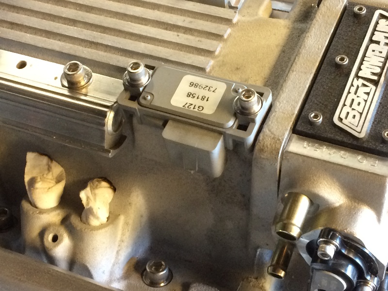
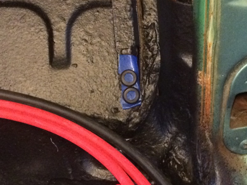
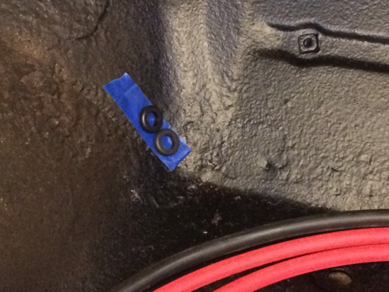
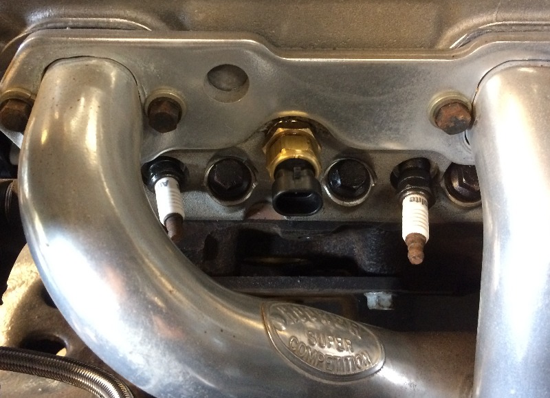
Got the MAP sensor (Manifold Absolute Pressure)
installed with four O-rings on the sensor probe,
that should seal it just fine....
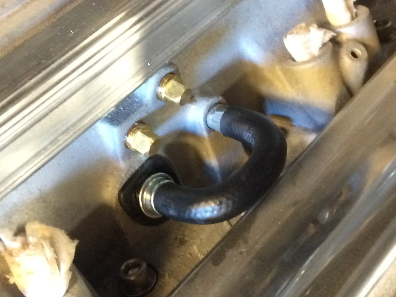
Put in the check valve for the crankcase ventiliation system
with it's special rubber grommet, and the vacuum connection
for that....
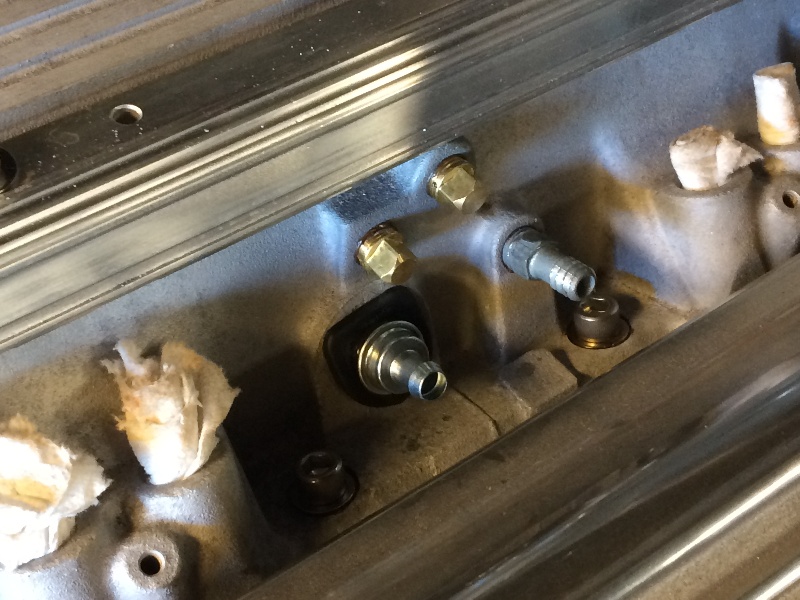
And stuck the hose on it....
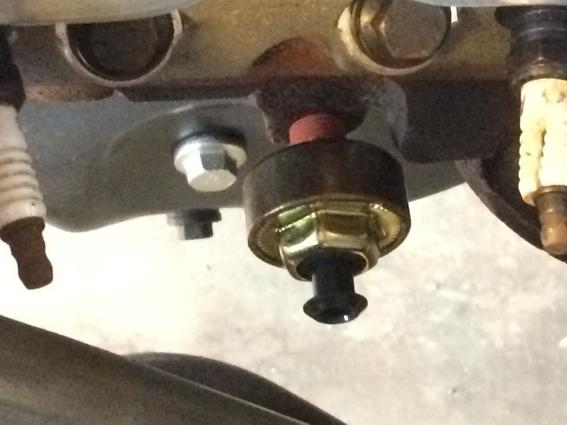
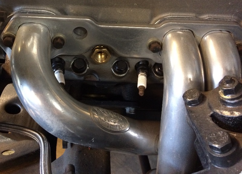
The only place on the block I can find for the
knock sensor was here down below the 5th
and 7th cylinders, I hope it's right....
I had to run a pipe thread tap in as the threads in the block
were pretty rusty, the sensor screwed in ok....
But it was a tight fit....
-
01-07-2019 #162
Registered User
- Join Date
- Feb 2007
- Location
- Hawaii
- Posts
- 225
Update on my list of sensors needed for this
'93 LT1 speed-density efi system:
1. MAT
Manifold Air Temperature
This fits in the air ducting in front of the throttle body,
I found one, need to figure out where to put it.
2. ECT
Engine Coolant Temperature
I found one, now I need to figure
out where it goes....
3. IAC
Idle Air Control
This goes on the bottom of
of the throttle body, I found one,
it is installed.
4. TPS
Throttle Position Sensor
This goes on the throttle body,
on the end of the shaft,
I found one, it is installed.
5. MAP
Manifold Absolute Pressure
Bought a new one from Napa,
it needs a special seal that did not come with it,
but I found four o-rings that fit nicely,
it is installed
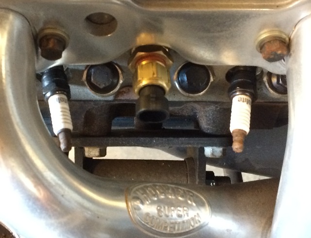
6. Knock Sensor
I found one
and mounted it in a threaded hole in the block,
down next to cylinders 5 and 7.
7. O2 (Oxygen) Sensor
I have one, need to weld a bung
on one of the header collectors for it.
01-08-2019 #163
Registered User
- Join Date
- Feb 2007
- Location
- Hawaii
- Posts
- 225
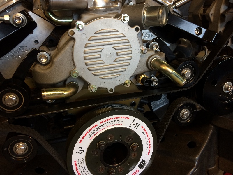
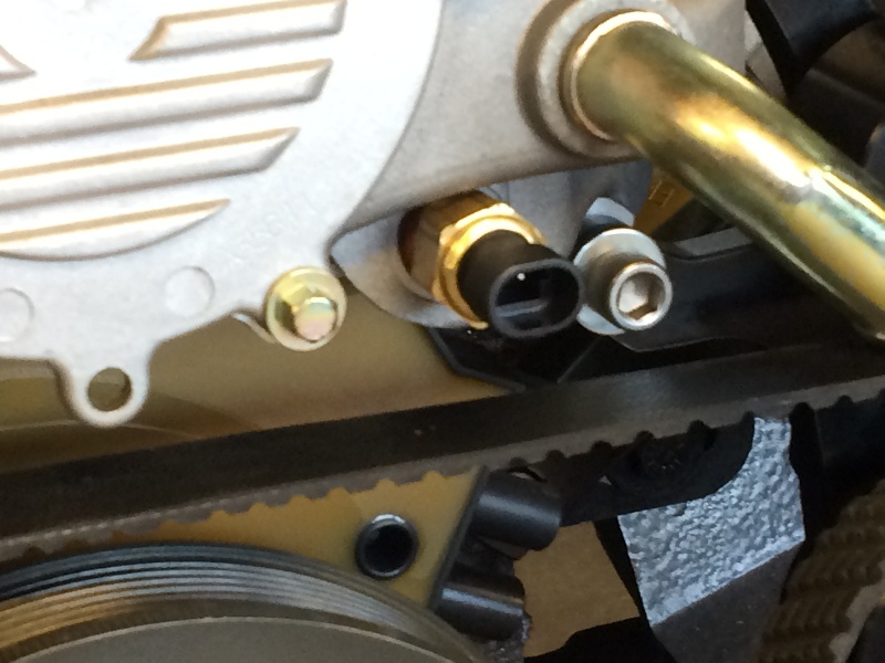
Got the ECT (engine coolant temp) sensor installed in a port
on the left side head between cylinders 1 and 3.
Then started working on hanging the new firewall pad on the inside under the dash...
01-08-2019 #164
Registered User
- Join Date
- Feb 2010
- Location
- New Smyrna Beach, FL
- Posts
- 116

The engine coolant temp on the head is for your gauge read out. The coolant temp the computer needs for input is located on the water pump. I have a 425 hp LT1 and T56 in my ‘87 S10. It’s been my daily driver for the last six years and it only broke down once, turned out to be a burned out ignition control model (literally a 5 minute fix). Your knock sensor will be fine, I have a street 90 pipe fitting on mine due to clearance issues. Awesome work, hope you get to drive your shoebox as much as I’ve driven my S10. Keep up the good work. And for this thread, mahalo!
Ben
01-09-2019 #165
Registered User
- Join Date
- Feb 2007
- Location
- Hawaii
- Posts
- 225
Thanks !
I'll go check that out, wasn't sure, and that port was all I could find, didn't check out the water pump all that thoroughly though...
Your S10 sounds like fun !
01-09-2019 #166
Registered User
- Join Date
- Feb 2007
- Location
- Hawaii
- Posts
- 225
Yup, many thanks, I moved it...
Now I have to find the right sensor for the temp gage...
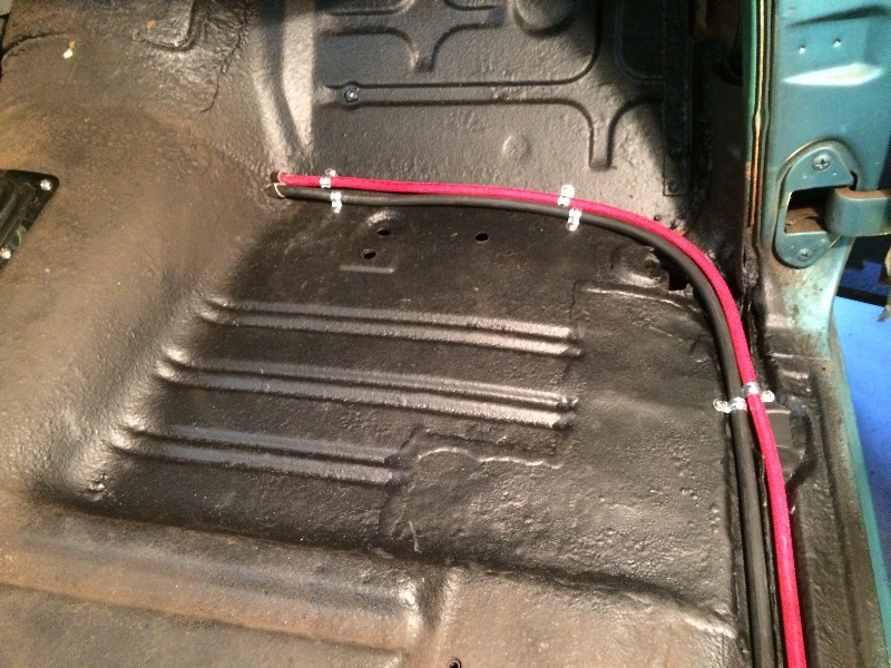
Ran the battery cables up to the firewall from the battery,
along the right side of the floor...
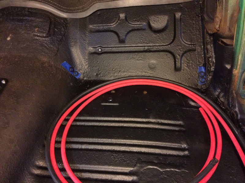
Now I have to decide if I want to put the cables through the firewall
here on the right side...
where I will have to run them across in front of the firewall to the starter and block....
Or run them across the front of the floor on the inside to the hump,
which put them very close to the starter and block on the other side....
Hmmmmmm.....
01-10-2019 #167
Registered User
- Join Date
- Nov 2017
- Location
- Lake Elsinore, CA
- Posts
- 90
Like you, I mulled that over in my head for a while. Happily, I just finished off the same job on my '55. Ran them in the same channel you're using, opened up the bottom of the pillar for a safe pass-thru and punched thru the firewall. Pics in my thread here and on tri-five. Lots of work but happy with the results.
Jeff
01-11-2019 #168
Registered User
- Join Date
- Feb 2007
- Location
- Hawaii
- Posts
- 225
Thanks Jeff,
This is probably my last build, at age 77 I'm feeling it more than any of the others, but I've been doing this stuff since I was 14, working with my Dad and his brother in Dad's shop on my '54 Chevy ragtop that I drove for another 11 years before I traded it in on a new El Camino, 327, 4 sp, posi, that was also a very fun car...
Meanwhile, went hunting for a temp sensor for the dash gage...
Found one at my local Napa store...
I haven't done anything about what dash gages I want to run,
still looking around, maybe go all digital ??
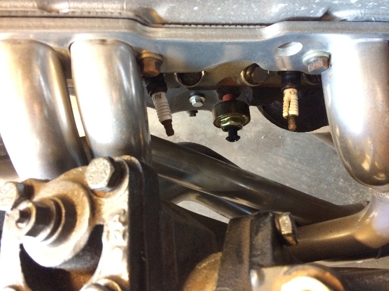
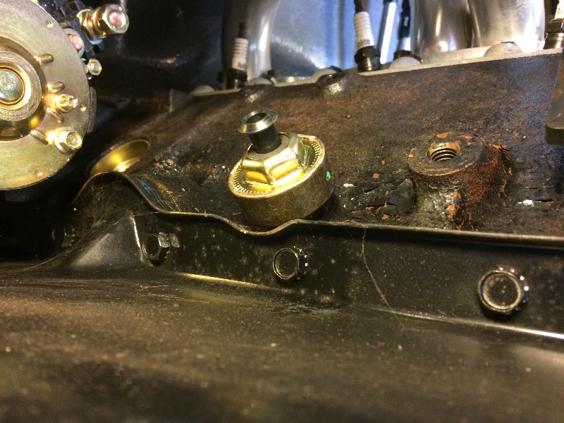
Meanwhile, I learned that the knock sensor would perform better
down here at this location on the right side of the motor near the
oil pan, in front of the starter, so moved it here...
01-20-2019 #169
Registered User
- Join Date
- Feb 2007
- Location
- Hawaii
- Posts
- 225
I did finish up the battery cables to the starter and engine block....
More pix here, scroll down...
01-21-2019 #170
Registered User
- Join Date
- Feb 2007
- Location
- Hawaii
- Posts
- 225
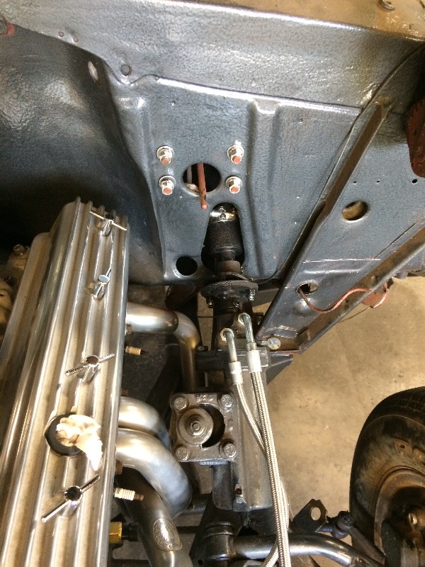
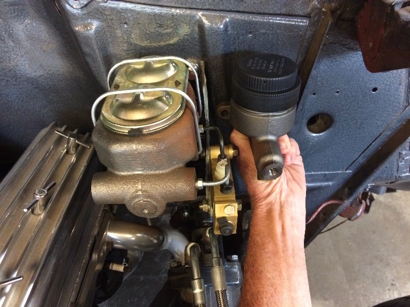
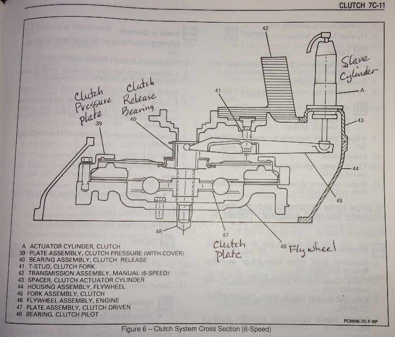
My T56 tranny clutch uses an exterior slave cylinder, and I need to find an appropriate mc and figure out the clutch pedal linkage to function properly. The aftermarket mc's I looked at are mounted on the right side of the brake mc and pedal, using the cross shaft setup of the stock '55 under the dash, and where they go through the firewall, they are perfectly positioned to hit my header tubes !!! I'll post some pix when I get some. My current thinking is to find an appropriate sized mc that I can mount on the firewall on the left side of the brake mc, and fab the appropriate linkage under the dash from the pedal that is on the left of the brake pedal, through the firewall to activate it. Shouldn't be hard to do, but I need to figure out what size mc bore to use, and how much leverage I need at the pedal to actuate it correctly. Part of that is the bore of the slave cylinder, and how much movement it needs to actuate the clutch properly. All data I do not currently have.
Another big "Hmmmmm" to solve....
-Willy-
01-21-2019 #171
Registered User
- Join Date
- Nov 2017
- Location
- Lake Elsinore, CA
- Posts
- 90
Willy,
I made up a bracket that mounts behind my master cylinder and utilizes the GM clutch master cylinder (2000 Camaro). I figured if I used the GM master and slave I'd be good to go.
Minor mods to the '55 pedal and I have a bolt in system. Took some time to get it all figured out but should be just fine.
Jeff
01-21-2019 #172
Registered User
- Join Date
- Feb 2007
- Location
- Hawaii
- Posts
- 225
Jeff,
That's way, way cool, I'll hafta look closely at that, many Thanks !!
Meanwhile, this is what I was up to today along with a 6pack...
All right, lemme see if I can get this posted
in one piece after way too many beers...
My T56 has a hydraulic slave cylinder on it,
so I need to come up with a hydraulic master cylinder
to operate it...
The aftermarket ones I've looked at for the 55 Chevy
comes through the firewall down low where the mechanical
linkage used to come through, but the headers I'm using
interfere with that location, so I'm looking at alternatives...
Look at that hole down on the car's right of the steering column,
that's where the original mechanical linkage came through, I
used that hole when I built "Patches", my 55 blown rat rod gasser...
Unfortunately it's way too close to the header pipe
for the heavily angled hydraulic system I've seen that is
designed to come down through that hole, so I'm
going to design my own system...
I have this master cylinder on the shelf that has a 7/8" bore and
a max stroke of 1-5/8", so I have to engineer a system for that...
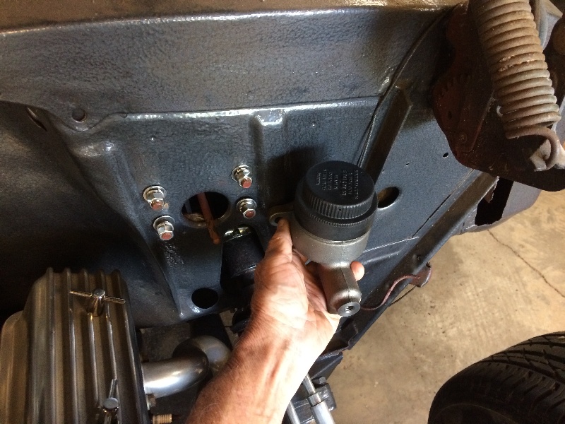
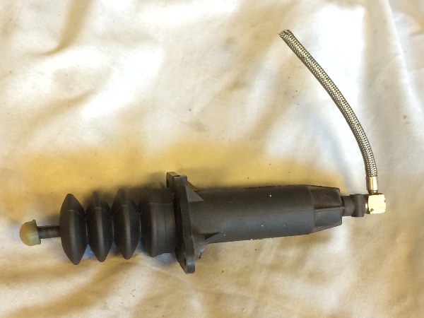
This is the slave cylinder that came out of my wrecked '93 Camaro
on the T56 tranny, it is a 1" bore and 1-5/8" max stroke...
Here's the original clutch pedal, held in front of the firewall....
as you can see it crosses over through the brake pedal pivot,
and the original linkage came down through that hole that
is now too close to the headers for a hydraulic setup....
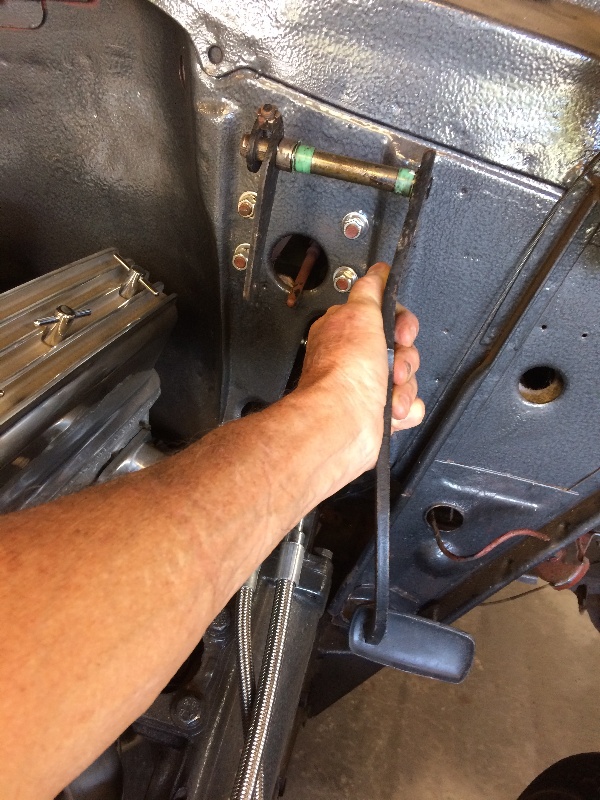
So I'm going to engineer adding a lever on the left side of that setup
to actuate that master cylinder, I need to find out the stroke required
for the clutch, then I can locate the master cylinder and how much
pedal movement and master cylinder stroke by locating the MC
at the proper location. The square of the diameters of the cylinders
represents the volume of fluid moved, that gives me a ratio of
0.77 to 1.00 with the mc at 0.875" and the slave at 1.00"
What fun !!!
01-22-2019 #173
Registered User
- Join Date
- Feb 2007
- Location
- Hawaii
- Posts
- 225
Here's a sketch of what I'm thinking...
design for a 1" movement at the slave
to operate the clutch, I hope that will be enough....
Extend the clutch pedal shaft on the left
and add a lever to give 2.7" effective swing
to activate the master cylinder with 1.3" movement...
The pedal has 5.5" of swing available at the floor
and is 11.5" long, the ratios are shown below....
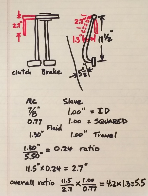
I hope this made sense....
01-23-2019 #174
Registered User
- Join Date
- Feb 2007
- Location
- Hawaii
- Posts
- 225
Ordered this setup from Dakota Digital....
It's quite a nice looking digital setup with analog display,
Another challenge to get it working the way I want....
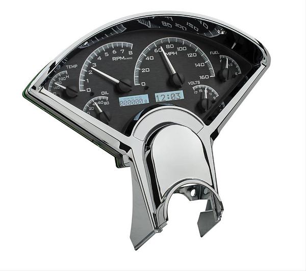
It's listed as a VHX 55 CKW
01-25-2019 #175
Registered User
- Join Date
- Feb 2007
- Location
- Hawaii
- Posts
- 225
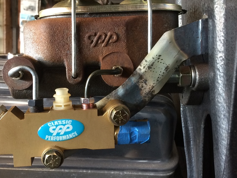
The 3/8" studs on the firewall to mount the brake mc, were too short for this thick flange on the mc...
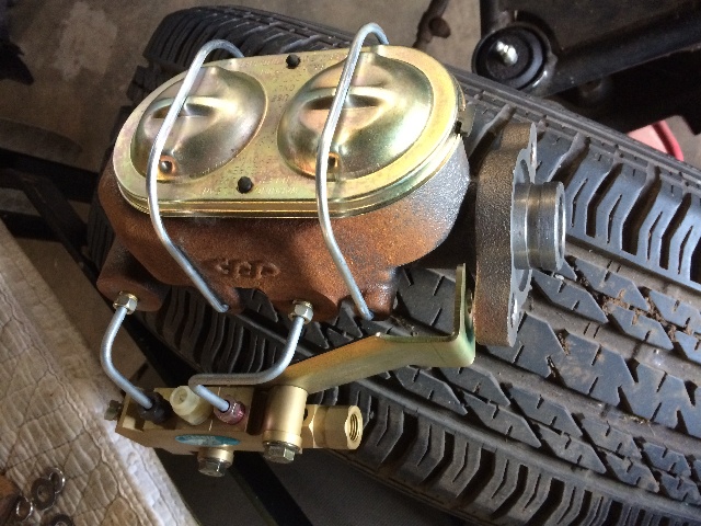
Looked at a couple of options, but the quickest was to cut the heads off a couple 1/2" bolts and thread them to fit over the 3/8" studs, with locktite....
That worked fine, except I can't get at the left side nut to tighten it with a wrench, the bracket
for the proportioning valve is in the way, so now I need to modify that bracket so I can get a
wrench in there to tighten that up...
more pix here
01-30-2019 #176
Registered User
- Join Date
- Feb 2007
- Location
- Hawaii
- Posts
- 225
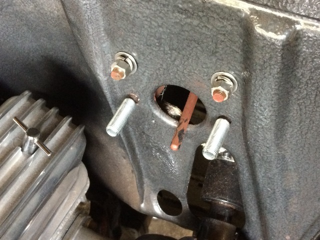
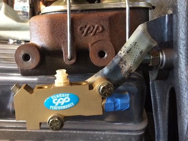
Had a few minutes yesterday, so worked on that proportioning
valve mounting bracket....
After some heating and hammering, I got what
looked like a pretty good fit, the mounting bolt
for the MC is exposed, and the rear MC brake line
connection is exposed, now let's make the connections
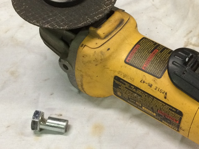
to the proportioning valve fit ok....
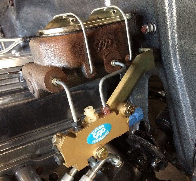
None of my brake tools will bend a tight enough
curve to get a good fit for these 3/16" steel short
lines from the MC to the proportioning valve, so I
ground a groove in a 1/2" bolt to try to bend and
get a good tight fit....
Started working the front connection first....
And ran out of time, will work on it some more tomorrow....
01-30-2019 #177
Registered User
- Join Date
- Feb 2007
- Location
- Hawaii
- Posts
- 225
But the rear one didn't look so good....
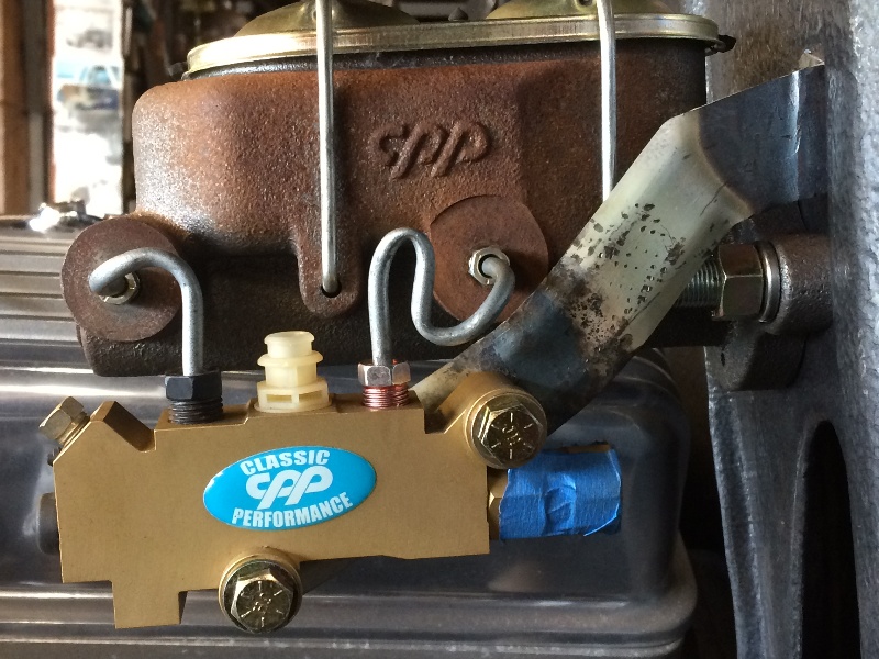
Went to NAPA and bought some new tubing
and it came out right this time....
Looks pretty good....
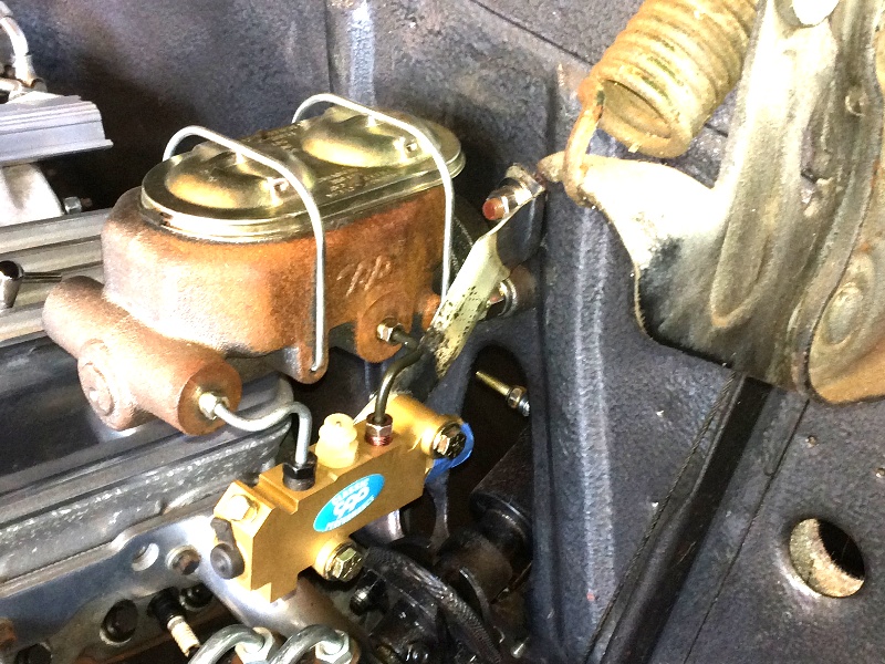
Plenty of room for the clutch hydraulic master cylinder....
Looking at the shop manual for the '93 camaro 6 speed
clutch setup, I realized I set it up wrong, it's a "PULL" clutch,
not the "standard" "PUSH" clutch, and I had assembled
it wrong, so now I hafta pull the tranny and clutch apart
and put that throw out bearing back in correctly so it
will "PULL" the clutch fingers to work the clutch....
Laters....
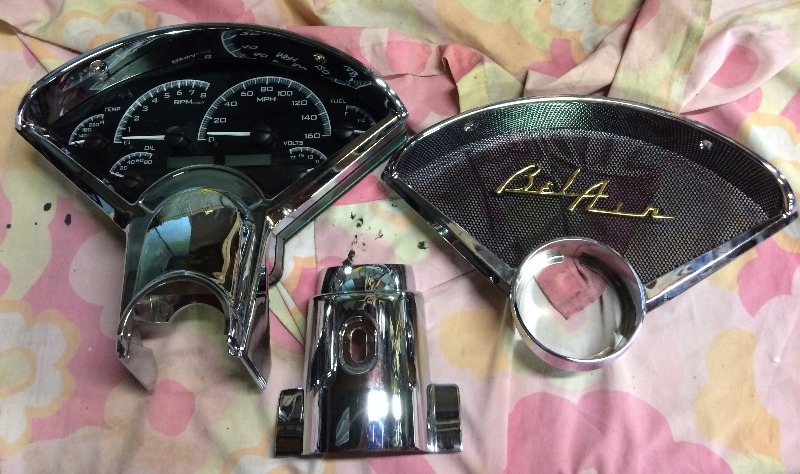
02-06-2019 #178
Registered User
- Join Date
- Feb 2007
- Location
- Hawaii
- Posts
- 225
Some flash for the dash arrived today,
Very Nice !!
02-06-2019 #179
Registered User
- Join Date
- Feb 2007
- Location
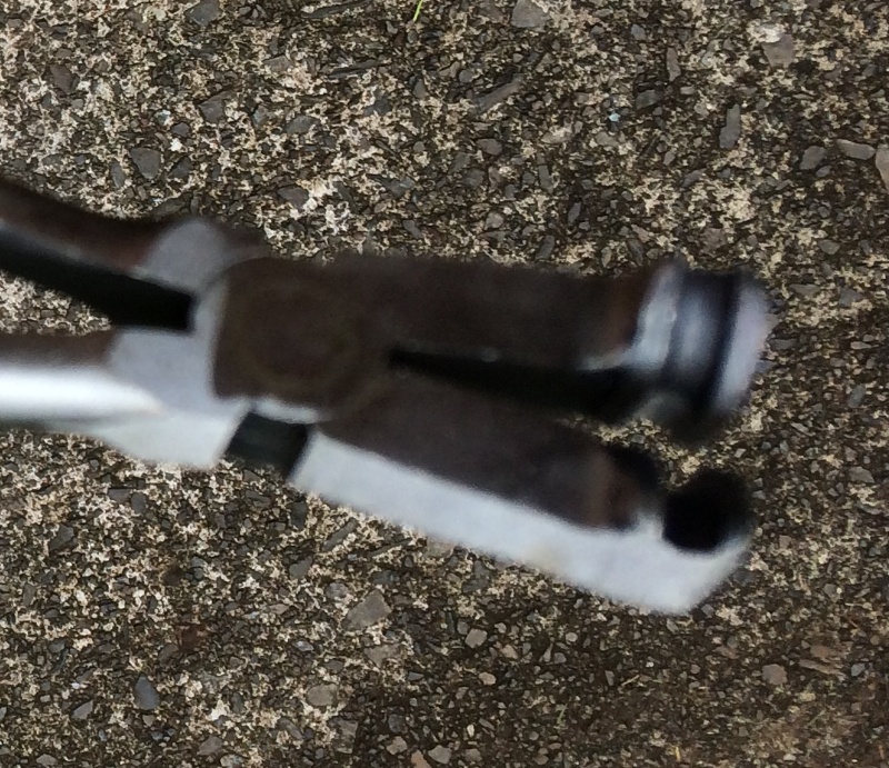
- Hawaii
- Posts
- 225
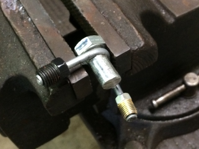
Found this 3/16" tubing bending pliers online,
I'll be using this from now on for these chores....
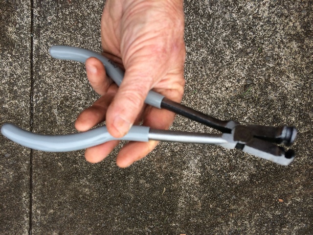
Not a very good pic, but a definite upgrade on my homemade grooved bolt....
02-06-2019 #180
Registered User
- Join Date
- Feb 2007
- Location
- Hawaii
- Posts
- 225
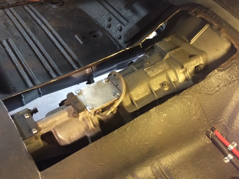
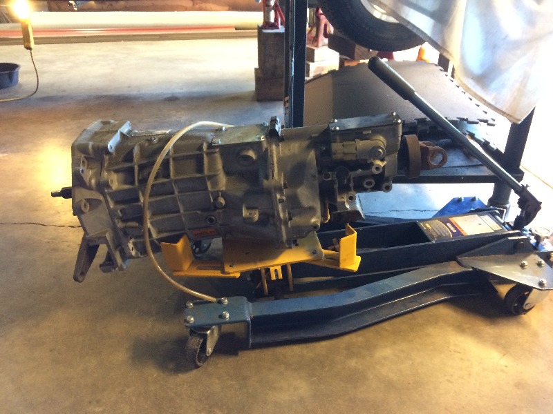
Pulled the stock '55 cover off the tranny tunnel inside,
not enough room, need more room....
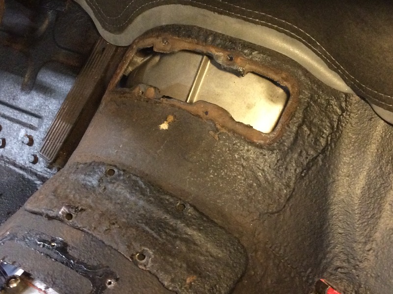
So I made some more room....
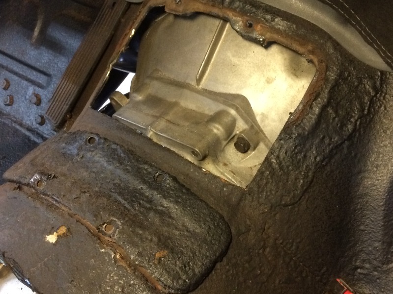
That helped, but the motor mounts will not "sag" to any degree....
so the tranny has to come straight back, need to cut more....
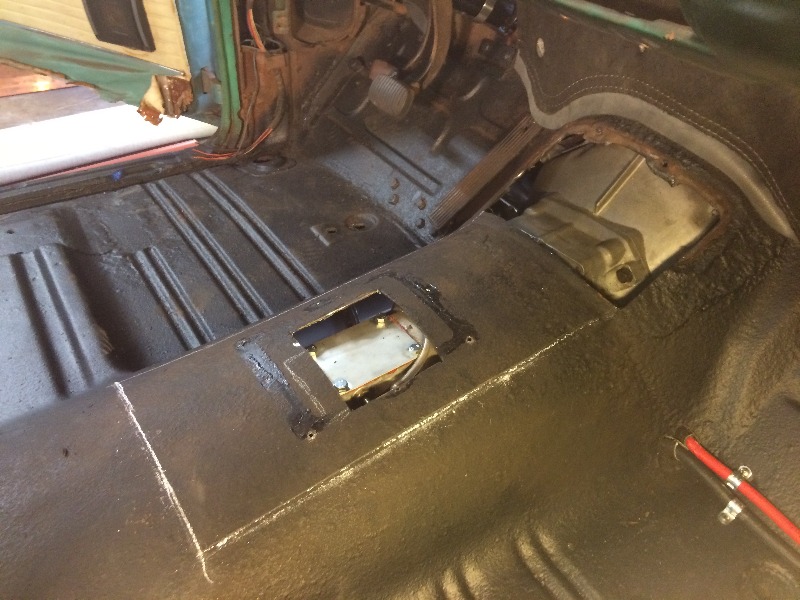
Ahhh, that 'll do it !!!
The tranny came right out now, and I'll have to fab some tab
strips along those edges to put the cut pieces back in place
with a bunch of sheet metal screws....
I used to wrestle these trannies in and out on my chest....
bench pressing them in and out with no problems....
Ha, finally broke down and bought a tranny jack....
Much, much easier....
Pour me another double scotch, bartender....

 Reply With Quote


