

Results 181 to 200 of 258
-
02-08-2019 #181
 Registered User
- Join Date
- Feb 2007
- Location
- Hawaii
- Posts
- 225
Still working on that clutch problem....
NAPA doesn't even list the clutch release bearing
for this application ('93 Z28 LT1 T56)
I had to go online and found this one on ebay....
I consider that a fairly huge failure for NAPA that they
don't list this part for that Camaro....
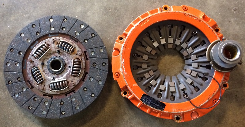
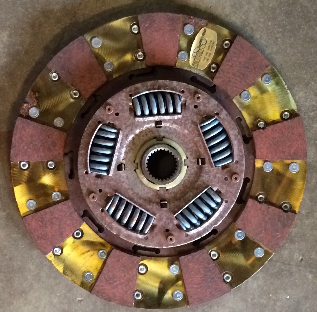
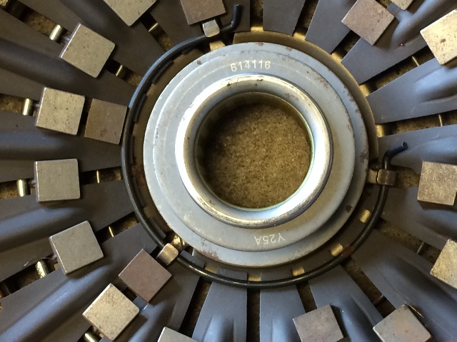
The clutch plate I selected has the organic material on the pressure plate side....
And the metallic pads on the flywheel side....
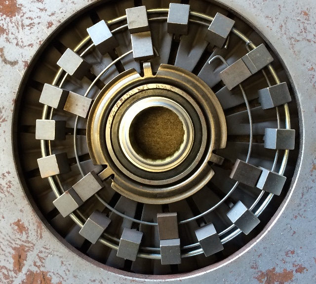
I had to look closely to see that there were three
openings between those fingers there that the three clips
on the release bearing fit into from the motor side of the clutch....
It just 'clicked' into place with a little 'persuasion'....
And a retaining ring clicked into place on the tranny side....
The clutch release arm has a sliding capability so the
tranny can be bolted up, then the arm is repositioned
to engage the release bearing collar...
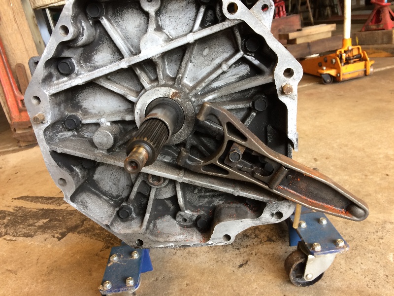
like this....
The clutch bolted up to the flywheel no problem,
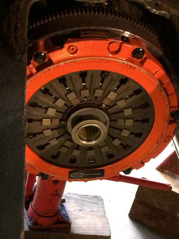
And, yes, I did align the clutch disk with an old tranny input shaft....
Now to fab attachment points for a new cover....
More Later....
-
02-10-2019 #182
Registered User
- Join Date
- Feb 2007
- Location
- Hawaii
- Posts
- 225
Dug around in my scrap pile until I found this piece of 14 ga.....
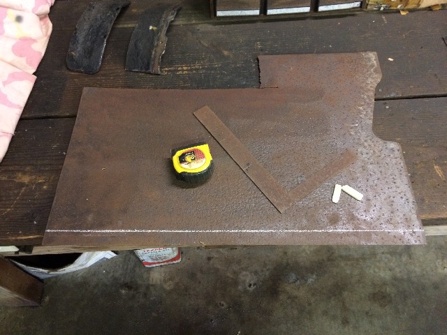
And cut 2 pcs 1" wide....
I'll fit these in under the edges of the opening
to mount the cut pieces back in...
02-10-2019 #183
Registered User
- Join Date
- Feb 2007
- Location
- Hawaii
- Posts
- 225
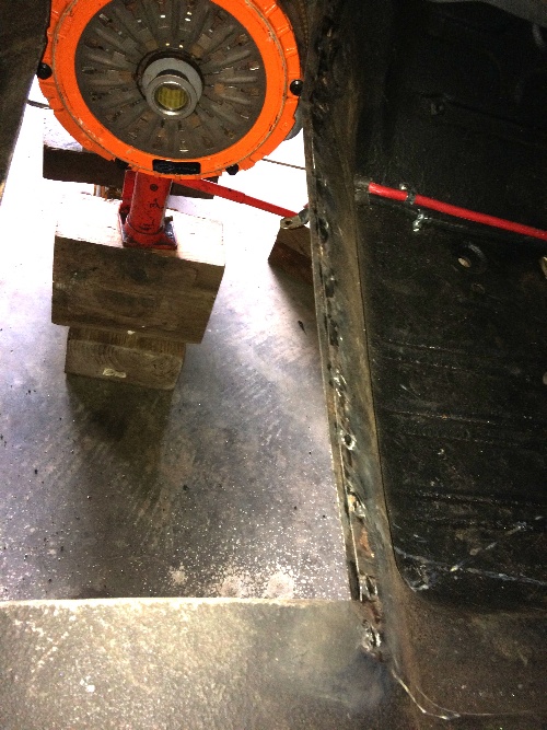
Had a few minutes so drilled 1/4" holes 2" apart in the floor along
the right edge of the opening, and spot welded one if the
1" strips under that side with 1/2" exposed....
02-16-2019 #184
Registered User
- Join Date
- Feb 2007
- Location
- Hawaii
- Posts
- 225
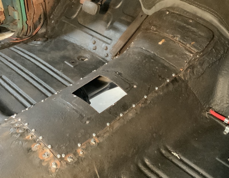
Found a couple of minutes to do a little more....
Got three sides done...
Trial fit looks good
Will add some additional welds underneath....
02-18-2019 #185
Registered User
- Join Date
- Feb 2007
- Location
- Hawaii
- Posts
- 225
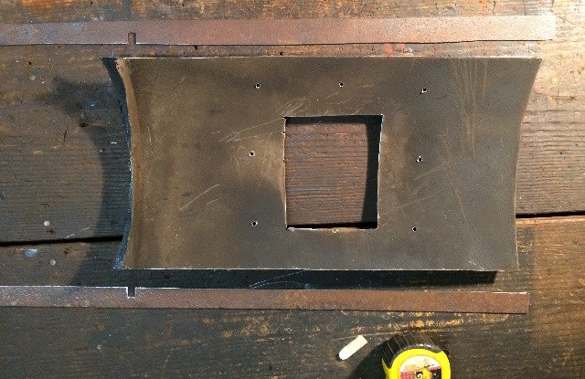
Tested some bits and settled on an 11/64" for the pilot hole
for these #10 sheet metal screws. Drilled them 2" apart,
will use this as a template to drill 11/64" holes in the strips
I welded in under the edges of the hole....
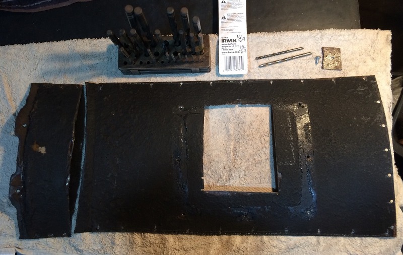
Later I'll drill these holes in the cover to 13/64" to better accomodate the screws...
02-24-2019 #186
Registered User
- Join Date
- Feb 2007
- Location
- Hawaii
- Posts
- 225
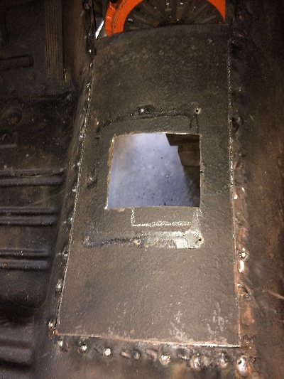
Been working on some other projects, but found a little time to go work on this...
Got all the screws in on the main cover....
It's solid, now to deal with those two upper pieces....
03-05-2019 #187
Registered User
- Join Date
- Feb 2007
- Location
- Hawaii
- Posts
- 225
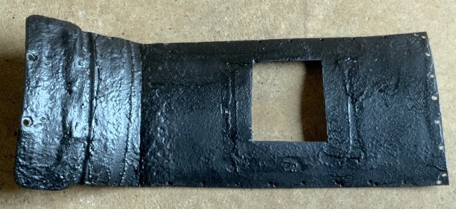
Had a few minutes so I welded the three pieces together and painted it...
03-09-2019 #188
Registered User
- Join Date
- Feb 2007
- Location
- Hawaii
- Posts
- 225
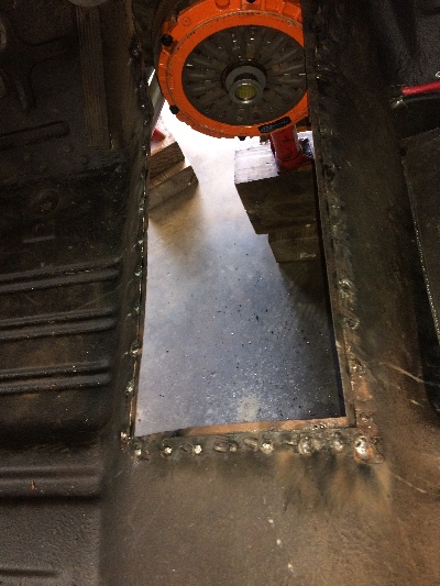
Ran into another problem with this clutch setup....
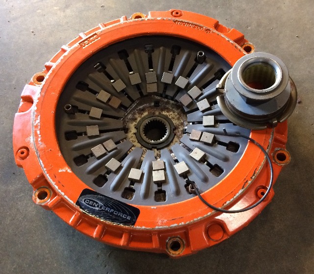
As I mentioned earlier this '93 Camaro 6 sp tranny uses an unusual "pull" type clutch setup...
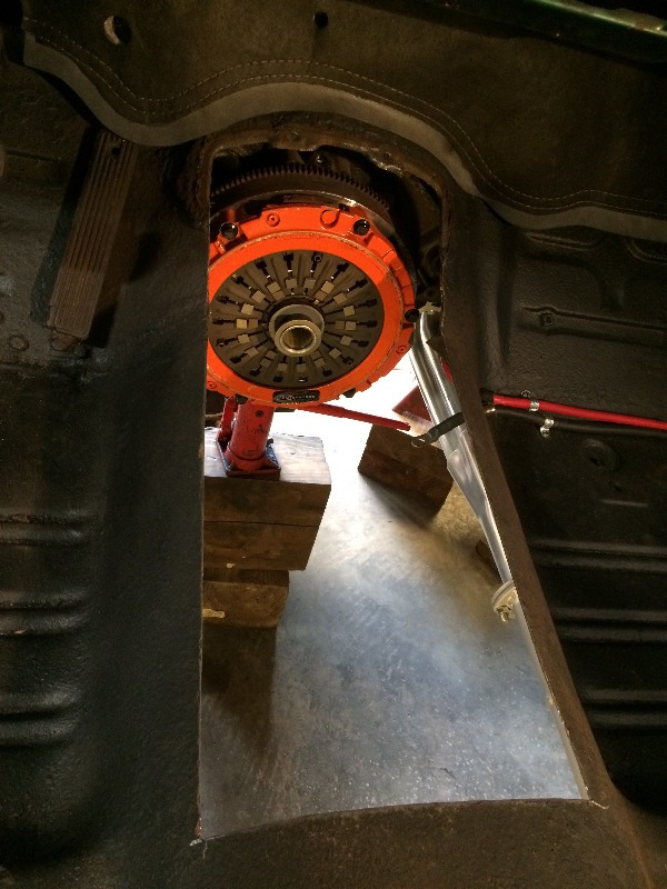
So I had to re-install the clutch release bearing in the clutch pressure plate from the motor side:
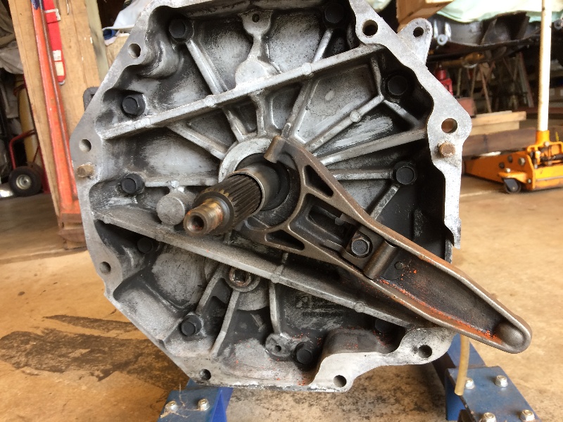
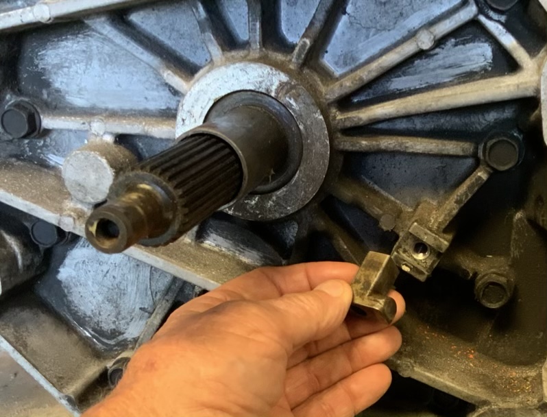
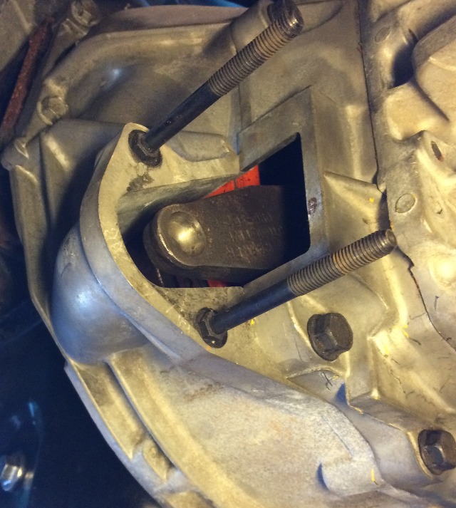
The procedure is to "retract" the clutch release arm, as shown here....
And after the tranny is reinstalled, I'm supposed to "relocate" the clutch release arm to this position, engaging the collar of the clutch release bearing...
So yesterday I got it all assembled, my "new" cover fitted nicely back on the floor, and tried to "shift" the clutch release arm into position on the clutch release bearing, and it won't go !
I should have "trial fitted" that fork on that bearing collar before I put it all together, and I didn't...
Something is wrong, the collar is to big or the fork is too small for that collar...
The fork is the original one out of the '93 Camaro LT1/T56 setup, but the clutch release bearing (and collar) is internet aftermarket, NAPA does not even list a release bearing for this application, which I find pretty strange, no listing for a 6 sp '93 Camaro ??
There is absolutely no access to this setup to see what the problem is, I'm guessing it's what I described above, as I laid under the car for quite awhile yesterday fiddling with it, and the fork just will not fit onto the bearing collar !
So I have to pull the tranny again, and check out why the fork won't go...
But I'm sure tempted to cut an access hole in the bell housing where I could get access to where the fork fits onto that collar, and fab a cover plate for it, but decided against that !
Yes, bartender, pour me a double scotch !
03-10-2019 #189
Registered User
- Join Date
- Feb 2007
- Location
- Hawaii
- Posts
- 225
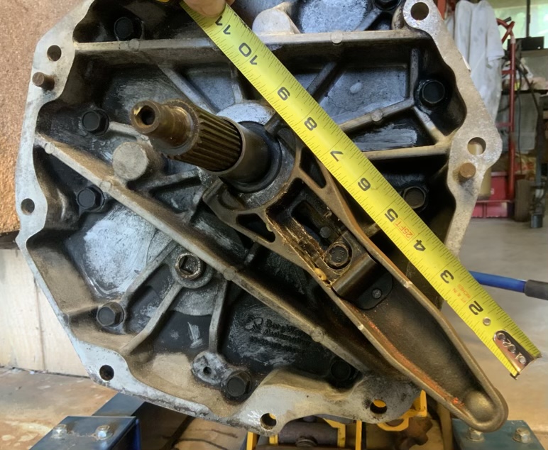
Pulled the tranny, removed the clutch fork, measured it, measured the clutch bearing collar,
and found that I had 0.025" clearance, so don't know why it wouldn't go, test fitted the fork
on the collar, no problem, so, what the heck ??
Put the tranny back in, but stopped about 3/4" short of being "home", shined a light up in there
while I fiddled with the fork, and it popped into place on the collar !!
Shoved the tranny all the way back in and bolted it up, put the tail shaft support and
driveshaft back in, all bolted up, and went back to look at the setup some more.
The front of the fork looks awfully close to the outer rim of the pressure plate housing to me,
not possible to get a pic of it, but it just doesn't look like there's enough room to fully
depress the clutch and disengage the pressure plate without hitting the fork against the
rim of the pressure plate assembly.
Two things I can think of, this pressure plate assembly is larger than the stock unit, bringing
the rim of that housing closer to the fork, and/or the release bearing and collar is longer then
the stock design, pushing the inner end of the fork toward the rear, and the outer end of
the fork closer to the pressure plate rim.
Wish I had some good specs of what that clearance between the front edge of the fork
and the outer rear rim of the pressure plate should be....
The fork pivot assembly has a rectangular mounting base that fits snugly into a
rectangular slot on the front of the tranny housing, that I could machine if needed
to move the pivot point rearward, allowing more clearance between the fork and
that pressure plate rim.
I wonder where I might find that kind of information... ?
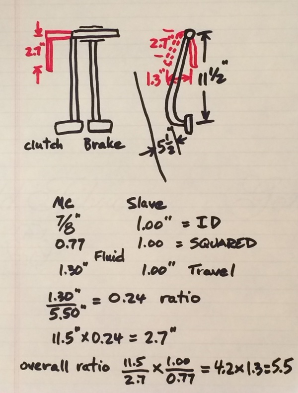
This sketch below I posted earlier showing my thoughts on one way to engineer the clutch
linkage shows a max movement available at the slave cylinder of 1", with a hydraulic
pressure available at the slave cylinder of 5.5 times my foot pressure at the pedal.
Looking at it as closely as I can through the slave cylinder opening, it looks like the
clearance between the fork and the pressure plate housing is only about 1/2", if that!
Guess I'm going to have to figure out a way to try to pin down how much clearance
is actually available in there, and try to find out how much I need!
Bartender, just leave the bottle....
03-11-2019 #190
Registered User
- Join Date
- Feb 2007
- Location
- Hawaii
- Posts
- 225
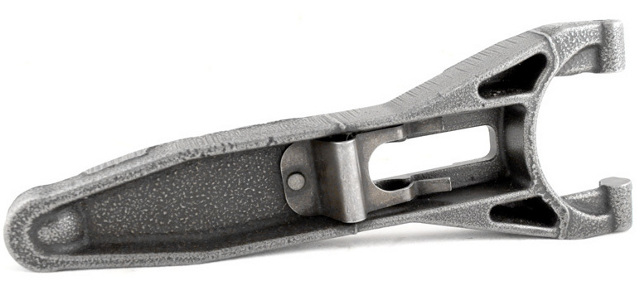
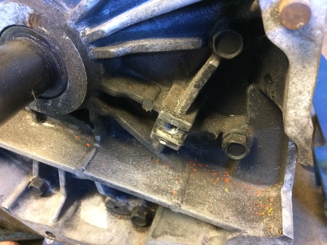
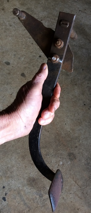
This is what my '93 Camaro six speed clutch release fork looks like...
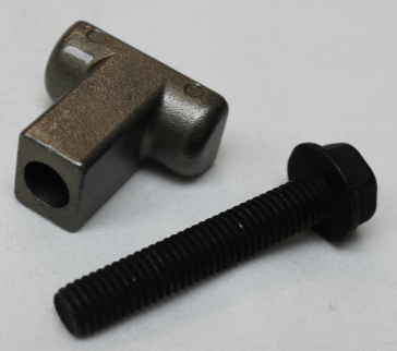
That T-stud and bolt is what it pivots on...
Chevy also had a 5 speed option for the Camaro,
it is the "old style" clutch setup...
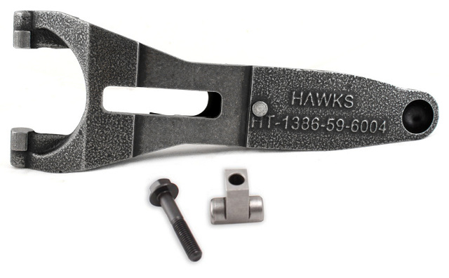
A view of the back side...
You can see how it slides in and out to engage the clutch release bearing collar
during assembly/installation...
By carefully milling the base of that T-stud to shorten it,
I should be able to locate the fork away from the pressure plate
where it can function correctly....
Now I need to figure out how to measure the existing "clearance" between the fork and the hub of the pressure plate...
And here's another good question, how much movement do I need at the clutch release bearing to get complete disengagement of the pressure plate ??
Hmmmm.....
03-11-2019 #191
Registered User
- Join Date
- Feb 2007
- Location
- Hawaii
- Posts
- 225
Pulled the tranny and started taking measurements....
Getting faster, only took 30 minutes to get it out of the car this time...
Probably getting more measurements than I really need....
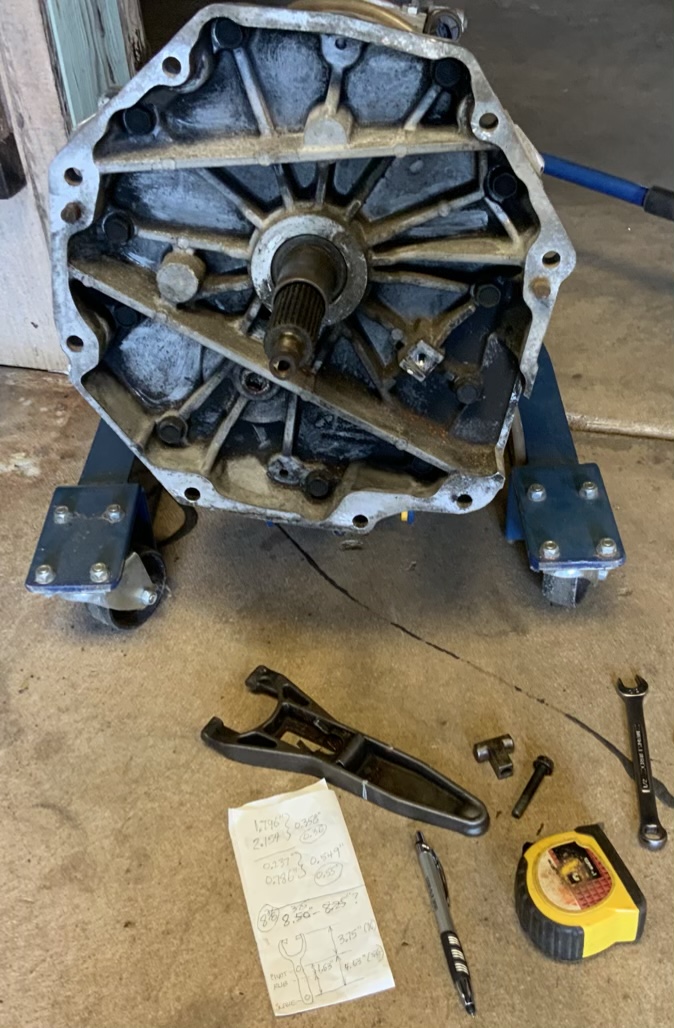
But by milling off some of the bottom of this "Tee Stud" that the fork arm
rides on, I can move the fork back away from the pressure plate...
I went online and found a spare "tee stud", so now I have
a backup on the way just in case I mess this one up....
Later....
Willy
More pix here....
03-12-2019 #192
Registered User
- Join Date
- Feb 2007
- Location
- Hawaii
- Posts
- 225
Tried my hand at some calcs, hope I'm doing this correctly....
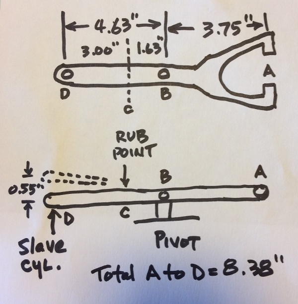
Marked the fork end "A", the pivot "B", the rubbing point "C", and the slave cylinder at "D".
The ratio of 1.63" / 4.63" = 0.35, which means the closer to point B you get, the less the fork
moves toward the pressure plate housing, so 0.35 times the movement at point "D", 0.55"
gives a movement of 0.19" to contact at point "C", that is, the clearance at point "C" is only 0.19"
when the fork is not doing it's job.
Shortening the Tee stud to gain more clearance at point "C" is quite doable, but how much??
My slave cylinder at point "D" is capable of 1" of movement, plus I want clearance at point "C"
if point "D" is at full movement of 1". So, first let's see how much movement there will be at
point "C" if I can move point "D" a full one inch....
Using ratios, 1" of movement at 4.63" from "B" to find "x" at 1.63" from "B", or:
1/4.63 = x/1.63, or:
x=1.63(1/4.63) = 0.35"
Now to calc how much to shorten the Tee post at point "B", we need to consider the fork as
fixed at the release bearing, point "A", and calc ratios from there...
Since point "D" now has 0.55" movement before it hits, let's calc the additional it needs before it hits
for a full 1" of movement: 1" - 0.55" = 0.45" additional movement is needed,
figuring from point "A", 0.45"/8.38" = x/3.75", or:
x=3.75(0.45/8.38) = 0.20"
So if I shortened the Tee post by 0.20" I would have a full inch of movement
at point "D" where the fork would then hit the pressure plate.
Ok, if I shortened the Tee post at "B" to give 1.5" movement at "D", how much
would I have to shorten it??
First the additional movement needed at "D", 1.50" - 0.55" = 0.95"
Again, ratios: 0.95/8.38 = x/3.75
x = 3.75 (0.95/8.38) = 0.43"
That's a lot to take off of that Tee post !
1.5" movement at "D" will give how much movement at "C" to contact the pressue plate?
1.5"/4.63" = x/1.63"
x=1.63(1.5/4.63) = 0.53" at "C" to contact the pressure plate.
If the clearance at "C" is going to be zero with the shortened post at "B" and full 1.5" movement
at "D", what is the clearance at "C" with only 1" movement at "D" ??
0.5"/1.5" = x/0.53"
x = 0.53(0.5/1.5) = 0.18" clearance at point "C"
I do need to take a serious look at what other effects might come up if I shorten that Tee post 0.43" !!
03-12-2019 #193
Registered User
- Join Date
- Feb 2007
- Location
- Hawaii
- Posts
- 225
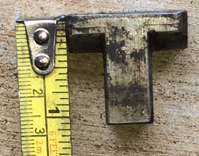
It's only 1.06" tall, removing 0.43" just leaves 0.63", not a lot !!
03-13-2019 #194
Registered User
- Join Date
- Feb 2007
- Location
- Hawaii
- Posts
- 225
Took another look at the Tee Post mount, the fork, and the release bearing...
There is only 0.512" protruding out of the fork...
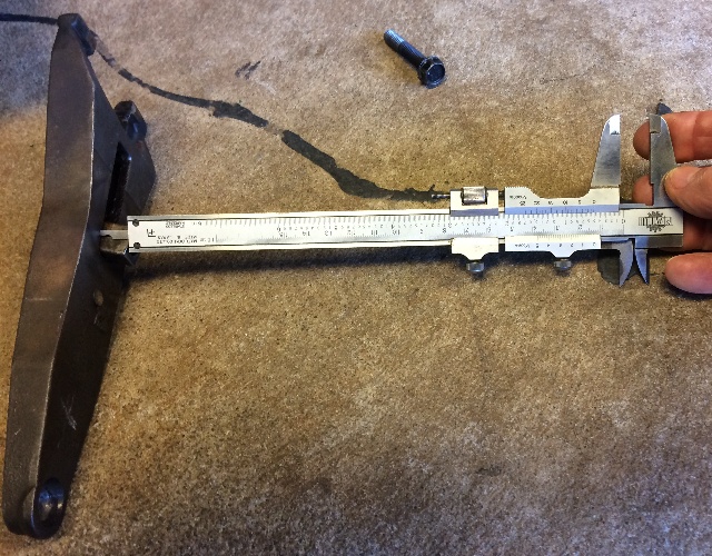
And those side rails on the mounting stand are 0.191" high,
that leaves 0.321" available to cut, but I also need to allow room
for the fork to rocker back and forth, how much do you suppose that is?
I tried to measure it, came up with about 0.025",
so that leaves only 0.296" max that can be cut !!
Had another thought though, let's check where the release bearing
sits on the tranny snout, I can measure that...
It turns out that the rear of the release bearing collar is
exactly flush with the rear edges of the bell housing...
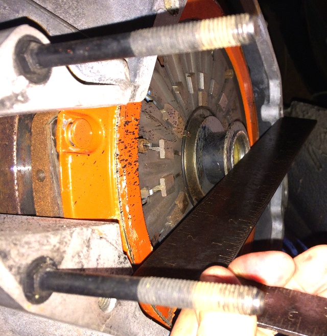
That means that the rear of the release bearing is also flush with the front
edge of the tranny, so with a straight edge I was able to measure just how
much travel the release bearing had available, turns out is is exactly 1/2" !!
Using the same ratios that I used above, 0.55" movement at point "D"
gives 0.44" at point "A" (the release bearing), but we
want 0.50" movement at the release bearing (point "A")
which requires 0.62" of travel at the slave cylinder (point "D")
Since I already have 0.55" travel available at point "D", I just need to
add 0.07" to get 0.62" movement at "D", getting 0.50" at the release bearing.
In order to get this, I only need to trim the tee post by 0.030"
But I'd be touching the pressure plate housing, so I need to add
additional clearance for the pressure plate...
I ran the numbers several times, and came up with these results:
Trim the tee post 0.080" gives 0.070" clearance,
Trim the tee post 0.100" gives 0.100" clearance,
Trim the tee post 0.150" gives 0.170" clearance,
It looks like all of these trim options will not cause other problems,
taking into account the angular movement of the fork on the tee post,
the amount of post exposed under the fork, and the amount of the tee post
required to fit into that base mount on the tranny, I have about 0.296"
available for a maximum trim job before I might run into a functional interference.
So, the real question is, just how much clearance do I really
need for the pressure plate housing ??
My feeling at this point is to trim the tee post 0.100" and see if I can live
with 0.100" clearance at the pressure plate housing...
The real problem is that I do not know just how much movement that clutch
needs to function properly, am searching for that number....
I'm pretty sure 0.500" is way over what's needed....
03-14-2019 #195
Registered User
- Join Date
- Feb 2007
- Location
- Hawaii
- Posts
- 225
Trimmed that tee post by 0.153”...
Let’s see how it all fits together now...
03-16-2019 #196
Registered User
- Join Date
- Feb 2007
- Location
- Hawaii
- Posts
- 225
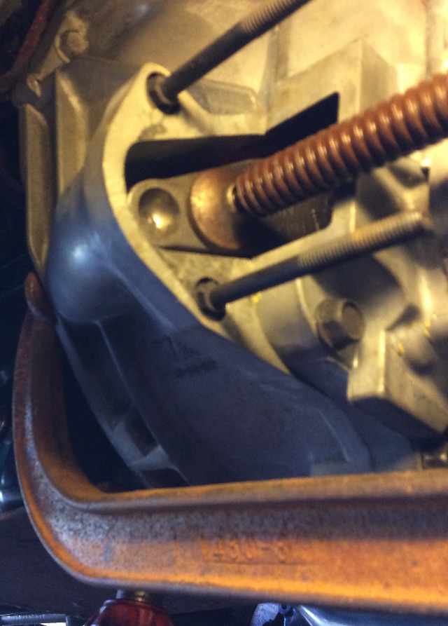
With the shortened tee post, I had to shorten the mounting bolt an equal amount, it was too long...
But the tee post and fork went back together nicely on the front of the tranny, no problems...
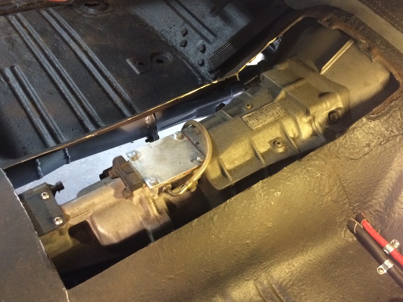
Put the tranny back in the car, the fork "popped" back into position nicely on the release bearing,
and I was able to get a measurement at this end of that fork...
Was able to get a pic, difficult to do under there...
This photo is misleading, the end of the fork actually now sits slightly above the surrounding metal...
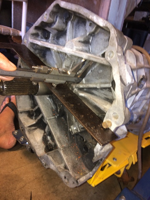
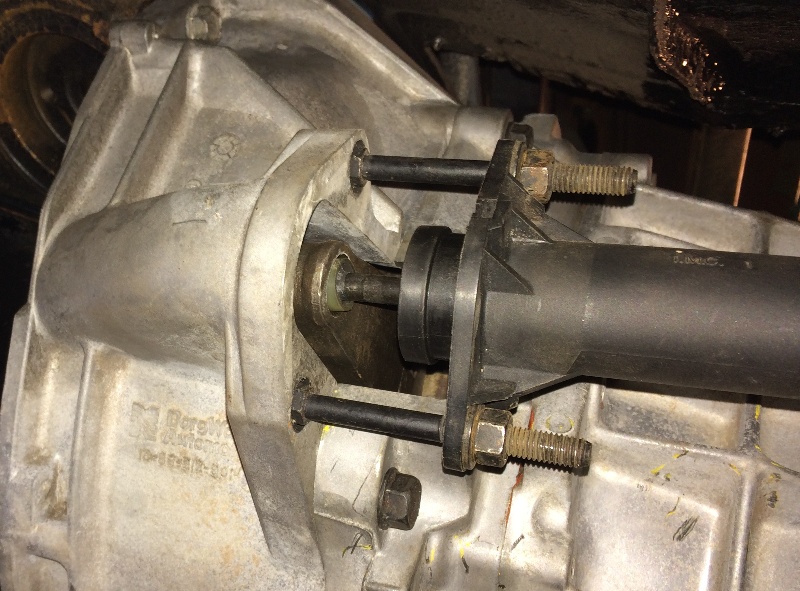
This pic shows the full movement of the clutch release bearing on the other end,
I measured 0.800" total movement at this end, and was able to determine
that there was plenty of clearance at the pressure plate housing....
I bent a heavy piece of wire and hooked it up in there under the fork, between the fork and
the pressure plate, and felt around a bit, when the fork was fully depressed, felt like plenty of clearance...
I still need to cut an inspection hole in the clutch cover, haven't made up my mind yet where and how big to make it....
03-19-2019 #197
Registered User
- Join Date
- Feb 2007
- Location
- Hawaii
- Posts
- 225
Haven't decided what to do about an inspection window yet, still mulling that over....
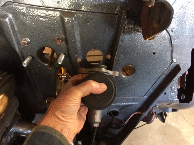
In the meantime, had to check out just where the clutch slave cylinder
will sit with the adjustments I've made to the clutch fork support setup....
Removed the support piece that goes between the cylinder
and the clutch housing, and mounted the slave cylinder
with the piston completely compressed inside the cylinder...
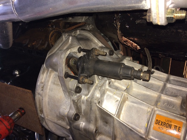
Measured this distance between the clutch housing and the cylinder, 1.643"...
Reassembled it with the support piece, which is 2.000" wide,
which gives me 0.357" of piston travel behind the
open cylinder still available behind the piston...
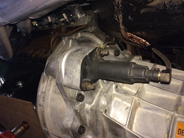
With a total stroke in the slave cylinder of 1.5",
and a max clutch fork movement of 0.80"
(probably less) I should be good to go with this setup!
03-21-2019 #198
Registered User
- Join Date
- Feb 2007
- Location
- Hawaii
- Posts
- 225
Put it all back together...
Now to look at the clutch pedal and linkage....

The chalk mark by that lower bolt is 2.7" down from the pivot...
Which is where I think I want to put the clutch
master cylinder push rod...
I think that this gives me the max. amount of leverage that I want to try for,
but should give me lots of foot pedal travel and a fairly light
pedal effort. If I move the attachment point further down, it
will increase foot pedal effort but give me a faster action at the pedal.
03-21-2019 #199 Registered User
- Join Date
- Nov 2006
- Location
- Ma.
- Posts
- 5,567

It came out nice
Wayne
Car FINALLY home !!!!!! lol
Project FNQUIK https://www.pro-touring.com/showthre...ghlight=FNQUIK
03-23-2019 #200
Registered User
- Join Date
- Feb 2007
- Location
- Hawaii
- Posts
- 225
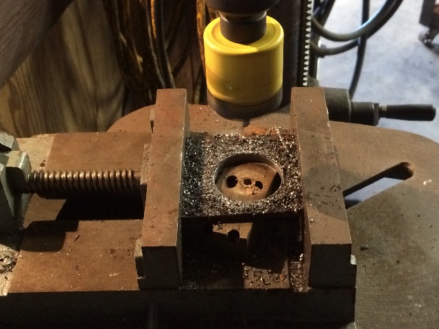
Got the hole saw out and started marking off measurements....
Drilled that hole first from the front side.
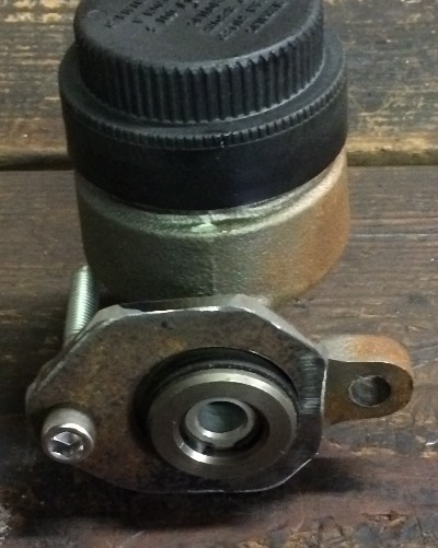
Had to pull off the brake MC to get access with the drill for the bolt holes...
Tried to get at the passenger side hole with the drill from underneath,
No Way, so off came the brake MC....
That "ridge" on the left side of the MC (viewed from the front) needed
to be flattened with a hammer, or a spacer needs to be fabbed....
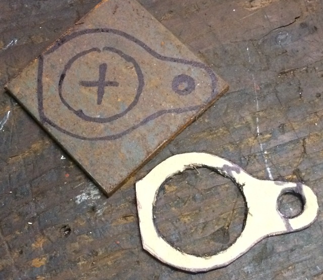
So made a pattern...
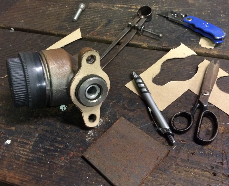
Had that piece of 1/4" in the scrap pile, so used that...
The pattern looks good to go....
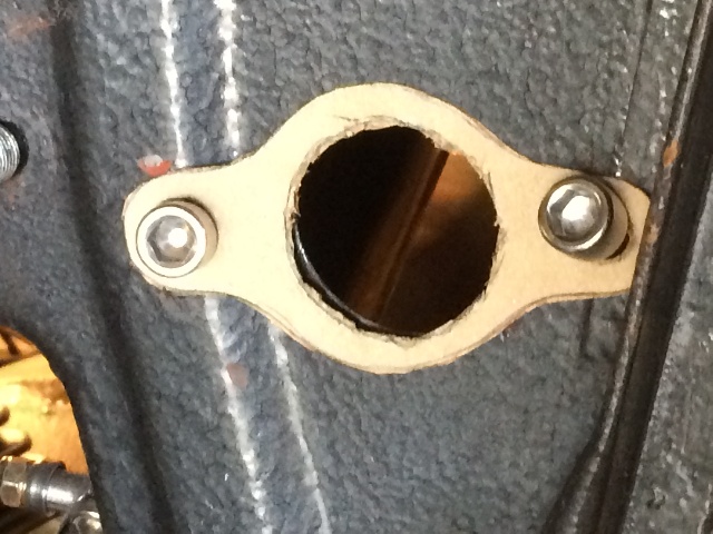
Gotta cut off the left side where the firewall ridge hits it...
Cut the big hole first....
Go from there....
Looks good on the MC...
Looks good on the firewall...
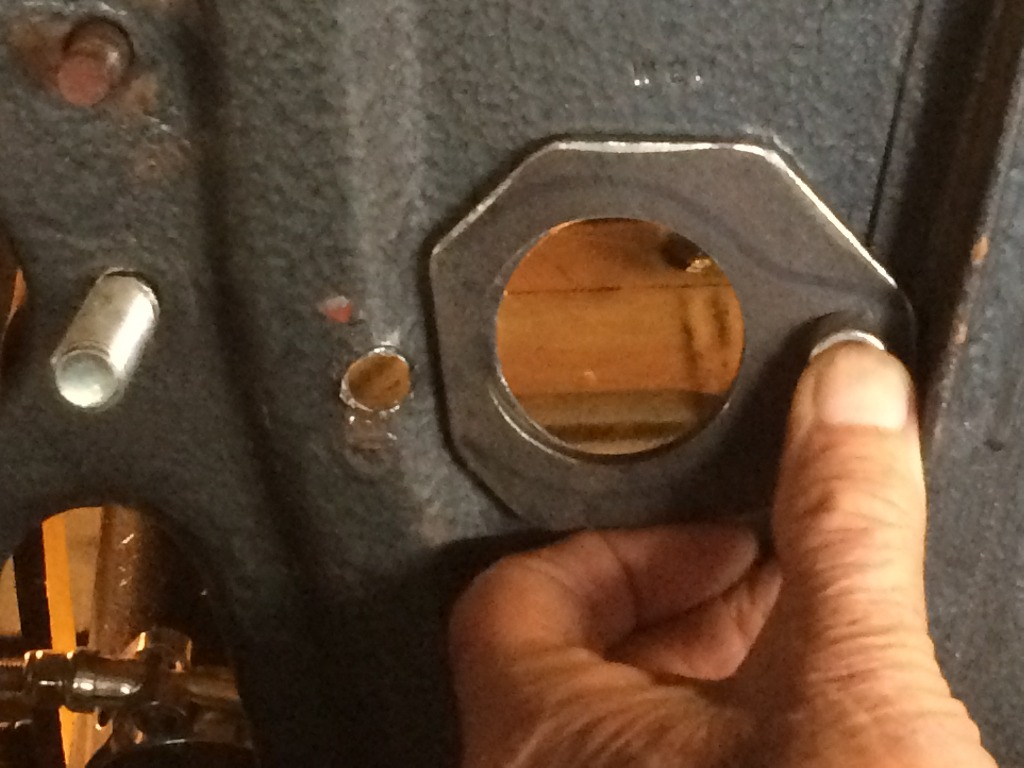
Need to fab another 1/4" plate for the inside, with the 3/8" bolts
welded on to stuff through and bolt up from the front side....

 Reply With Quote


