

Results 21 to 40 of 76
Thread: 1971 Pontiac Lemans Convertible
Hybrid View


-
08-05-2012 #1

 -Moderator/Sponsor-
- Join Date
- Apr 2001
- Location
- The City of Fountains
- Posts
- 16,118
 Thanks Phil. Glad I could be a source of inspiration.
 Originally Posted by fsdproject

If you were to do ATS spindles in the front, that solves the speed sensor issue there. In the rear, you can talk to Moser or one of the other rear end vendors and see about having a custom rear made that would incorporate sensors at the wheels. Remember, they make rear ends for 4th gen f-bodies, where the later year cars used a 4 channel ABS system. As far as weight, I'd say that a new GTO is right there along with an old GTO. As for wheels and tires, I see people swapping wheels and tires on new cars without any issues with the ABS. I think that if you were attempting to swap a fancy dynamic control system then this would be a problem, but for ABS, it might be simpler. Again, I don't know all this for sure, but you being an engineer should have a handle on things. Document the ABS swap, and you'll return the favor. :-)
I am looking forward to seeing this project progress.
Andrew1970 GTO Version 3.0
1967 Cougar build
GM High-Tech Performance feature
My YouTube Channel Please Subscribe!
Instagram @dr__efi
I deliver what EFI promises.
Remote Holley EFI tuning.
Please get in touch if I can be of service.
"You were the gun, your voice was the trigger, your bravery was the barrel, your eyes were the bullets." ~ Her
-
08-05-2012 #2
Registered User
- Join Date
- Jul 2012
- Location
- Lake Mary, FL
- Posts
- 158
Great build... really like the out of the box approach. Looking forward to following along. I am starting mine soon, so im sure I can pick up a few pointers..
 Jack~
Jack~
1969 Camaro Convertible - In Progress.
Body Mods, LSx TT Setup, T56, 4 Link, Lowered, the works.
08-05-2012 #3
Registered User
- Join Date
- Nov 2011
- Location
- Springfield, OH
- Posts
- 58
Andrew,
Thanks for the information on ABS. I do remember reading about the ATS spindles and the fact they have provisions for wheel speed sensors. I have kept everything I have taken off the GTO donor including the wheel speed sensors so as I said before the ABS swap is something I may do at a later date. I have my hands full now just trying to get the thing on the road! I do like the challenge of doing things that haven't been done before and this project certainly provides many challenges! When the time comes and I do successfully complete the ABS swap I will document it.
I hope to get this build thread up to date over the next few weeks to catch up with my actual progress on the car.
Phil
08-05-2012 #4
-Moderator/Sponsor-
- Join Date
- Apr 2001
- Location
- The City of Fountains
- Posts
- 16,118
Good luck on the project Phil. Looking forward to updates! Originally Posted by fsdproject
Andrew1970 GTO Version 3.0
1967 Cougar build
GM High-Tech Performance feature
My YouTube Channel Please Subscribe!
Instagram @dr__efi
I deliver what EFI promises.
Remote Holley EFI tuning.
Please get in touch if I can be of service.
"You were the gun, your voice was the trigger, your bravery was the barrel, your eyes were the bullets." ~ Her
08-08-2012 #5
Registered User
- Join Date
- Nov 2011
- Location
- Springfield, OH
- Posts
- 58
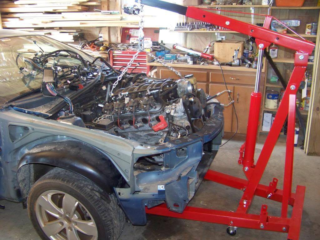
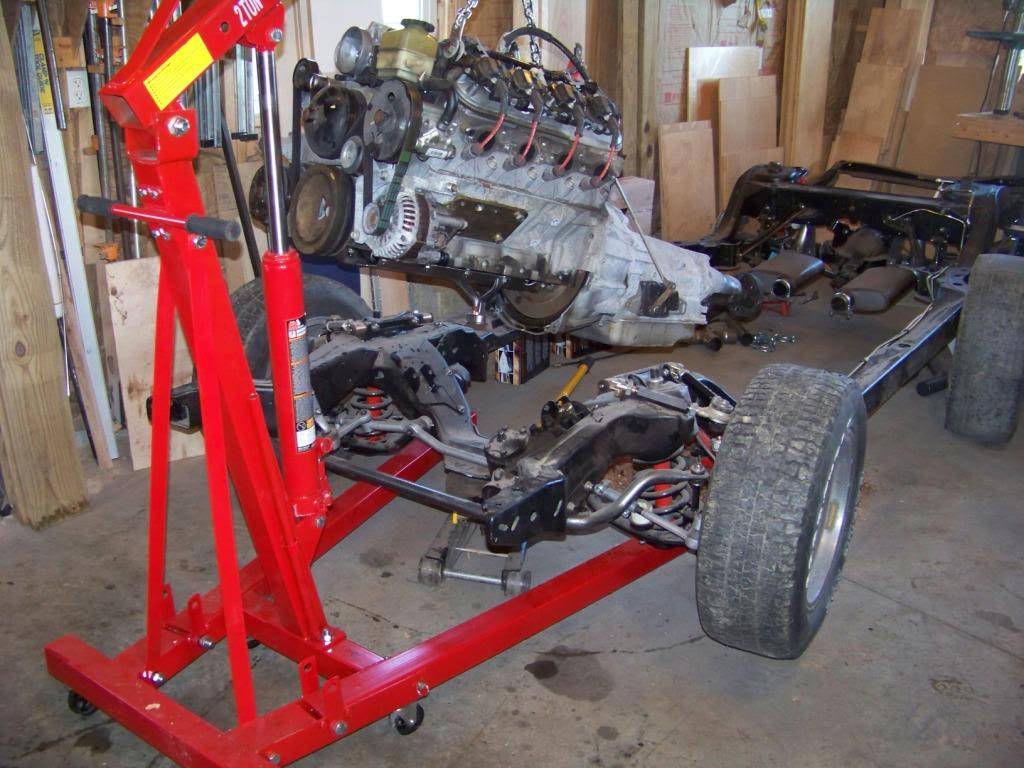
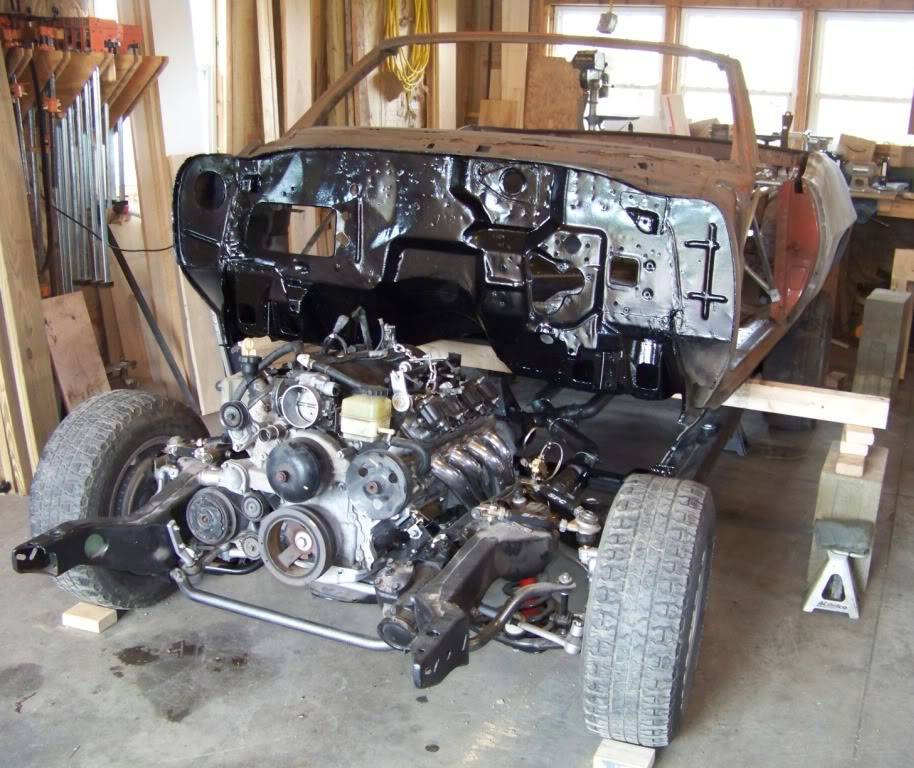
The donor car sat outside for a time while I got the frame ready. I ran stainless steel fuel and brake lines along the frame, I also used stainless vinyl covered clamps and fasteners for the lines to avoid future rust issues. I found these at McMaster, an online hardware store that has an extensive inventory.
In preparation for the swap I removed most of the front sheet metal from the GTO donor so it wouldn't get damaged. I took me a few days to drain fluids, disconnect things like the driveshaft, fluid hoses and lines, the electrical harness, and the mounts. I also removed the radiator and AC gear in the front so they wouldn't get damaged and I could use them in the Lemans. I couldn't find a hoist to borrow so I bought a 2-ton one at Tractor Supply for $200. It's a cheap Chinese one but it worked well for me. I also bought a engine lifting chain from Summit, part number SUM-G1027. The GTO's motor already had heavy sheet metal lifting brackets on the front of the driver's head and the back of the passenger head so I didn't have to bolt the chain to the engine. I used 3/4" grade 8 bolts with thick fender washers to attached the lifting chain to the lifting brackets on the motor. Lifting the motor was pretty uneventful.
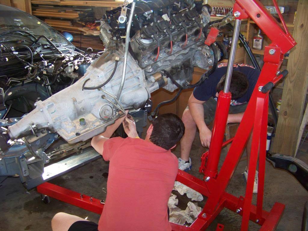
Once the motor was in the air some things had to be done before it could be moved to it's new home. Since the GTO donor has a front sump oil pan, that had to be replaced. I did quite a bit of research into all the options and went with the Holley 302-1 LS Retro-fit oil pan. It's a nicely made and good looking part, it's too bad it won't be noticed where it's going. I paid about $370 at Amazon, no tax or shipping. The pan comes with a new oil pickup tube. I also replaced the windage tray (GM 12611129) and used a new gasket (GM 12612350). This picture shows my son and his friend removing the original oil pan.
One minor unfortunate thing happened during this process, the bolt hole in the block for the pickup tube somehow got stripped, I drilled it out slightly larger and tapped it for a larger bolt.
Another issue with using GTO engines is that the dipstick goes into a hole in the oil pan instead of the side of the block like most other LS applications. A small sheet metal plug in the bottom passenger side of the block needs to be punched out from the inside to allow the installation of a dipstick there. This should be done while the oil pan is off the engine. I installed a dispstick tube (GM 12625031) and dipstick (GM 12634547) after the headers were installed. All of these part numbers are in the instructions that came with the Holley oil pan. Another thing I found was that the Holley oil pan uses a different oil filter than what the GTO requires - a PF48 instead of a PF46. I believe they differ in the thread size and pitch.
Next, motor mounts.Last edited by fsdproject; 08-08-2012 at 03:46 PM. Reason: Correct Part Number
08-08-2012 #6
Registered User
- Join Date
- Nov 2011
- Location
- Springfield, OH
- Posts
- 58
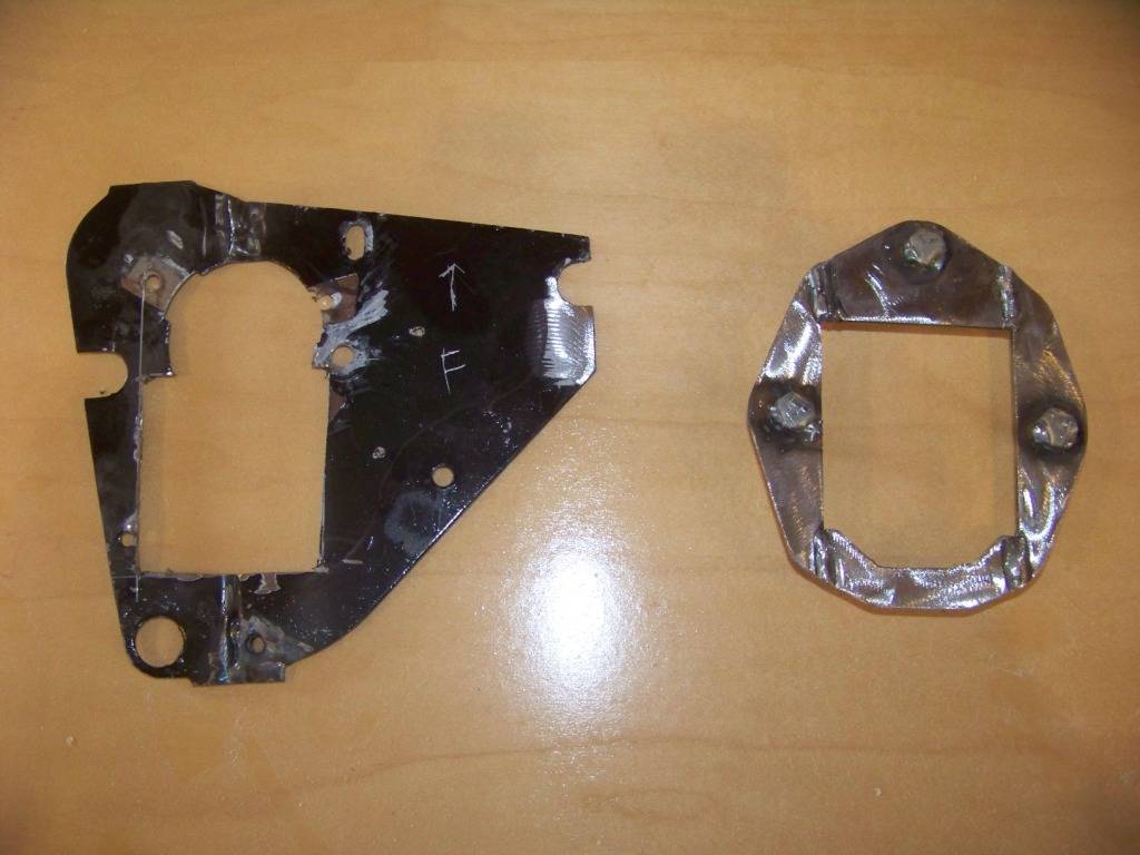
In researching motor mounts and adapter plates it seems like the two choices are normal and one inch setback. I got the impression the one inch setback plates are useful to avoid interference issues with the crossmember and to allow the engine to bolt to an existing transmission. I didn't have either of those issues, and I didn't like having the motor closer to the firewall and making access to the sensors and connections on the back of the motor more difficult. So I went with the normal adapter plates.
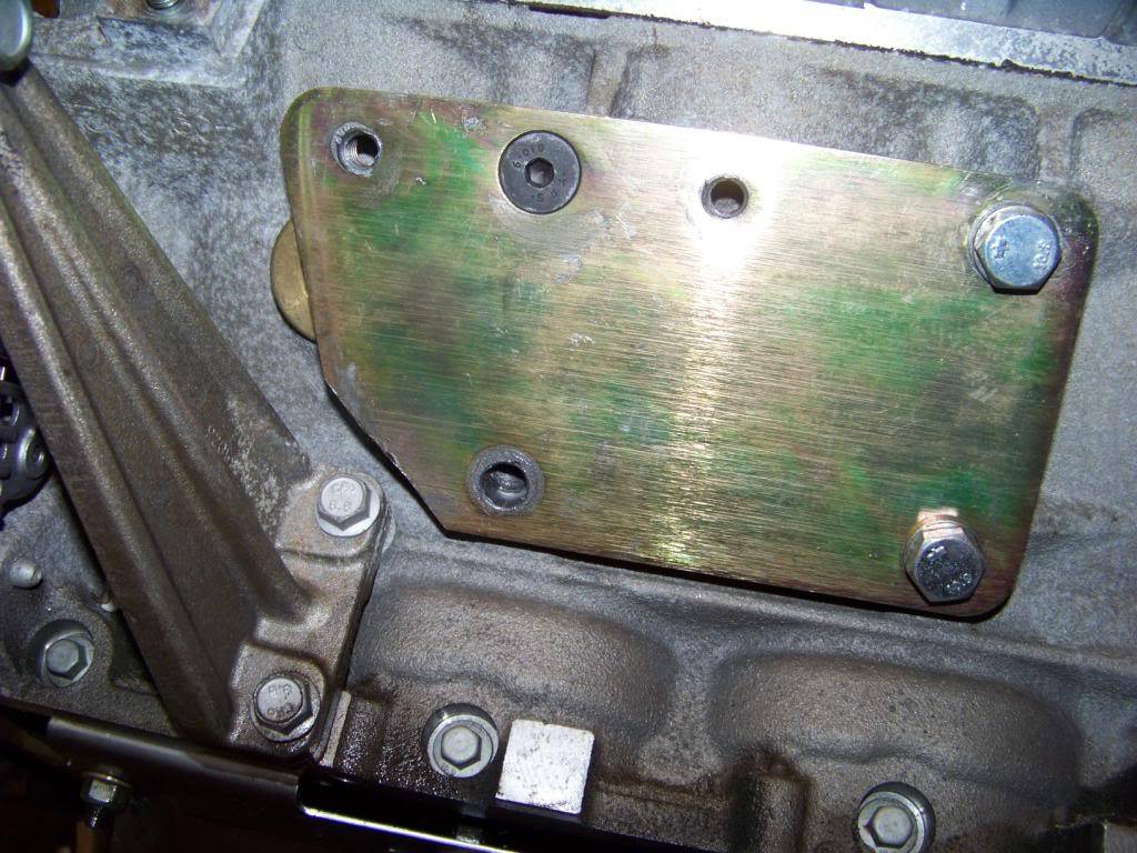
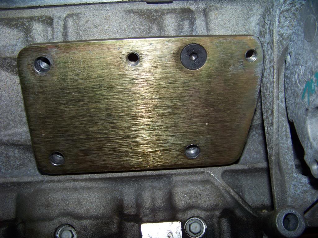
For adapter plates and motor mounts I went with the 3-1148G Motor Conversion Set from Energy Suspension. This set includes the adapter plates, short and wide poly engine mounts and all necessary fasteners needed. The parts are well made but the instructions were basically a parts list and torque diagram. I had a couple of issues with them.
The first issue was one of interference of the adapter plates with brackets on the engine that support accessories. The front lower corner of the adapter plate on the driver side interfered with the bracket for the alternator. The front upper corner of the adapter plate on the passenger side interfered with the bracket for the AC compressor. I called tech support for Energy Suspension and was told to just grind the edges of the plate as necessary to gain the needed clearance. Their tech support was very good, I got a person on the phone right away and he was very helpful. The pictures below (driver's side first, then passenger) show the installed plates with grinding done.
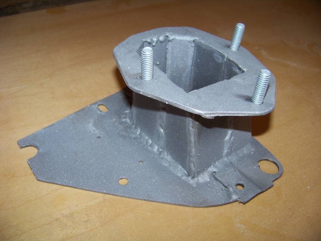
After I got the plates figured out I sandblasted them, primed and painted them so they wouldn't rust and installed them permanently.
The other issue came when I installed the motor mounts onto the adapter plate. On the "back" or upper surface of the mount there is a ridge in the poly that prevents the mount from sitting flush on the plate. When I called and asked about that I was told this area would get compressed when the bolts were tightened and that develops a necessary preload into the mount.
For the frame mounts I went with the Car Shop CSP2380 A Body frame mounts BOP to Chevy. These were attached to the crossmember with a stainless fastener kit from Totally Stainless.
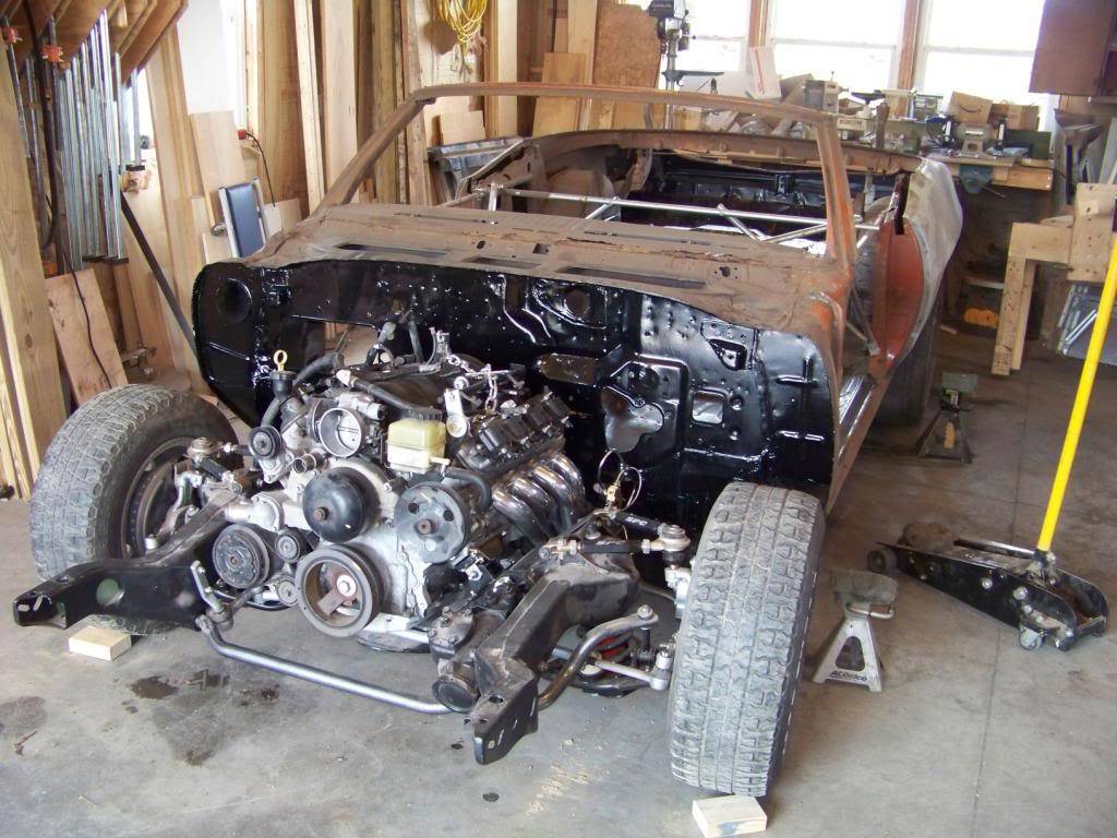
Once all these were in place it was time to lower the engine onto the Lemans' frame.
The only interference issue I ran into fitting the engine was between the alternator and steering box. It was pretty much preventing the engine from being bolted in on that side. I knew from my research that was a possible issue so was not surprised. I removed the alternator and it's supporting bracket from the engine to allow me to continue. I know I could have possibly trimmed the steering box, put spacers under the frame mounts, or used the smaller Camaro alternator, but wasn't really interested in any of those options. Plus, it appeared like the alternator would have been very hard to replace in the future if I left it in it's original location. I figured I would look into alternator relocation in the future.
I left the fasteners for the motor and frame mounts loose to help put the cross bolts through the mating holes in both mounts. With a little bit of shoving and pushing I got all the bolts in and tightened everything.
Next, headers and exhaust.
09-03-2012 #7
Registered User
- Join Date
- Nov 2011
- Location
- Springfield, OH
- Posts
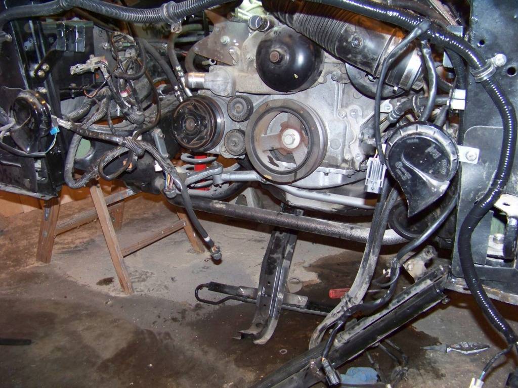
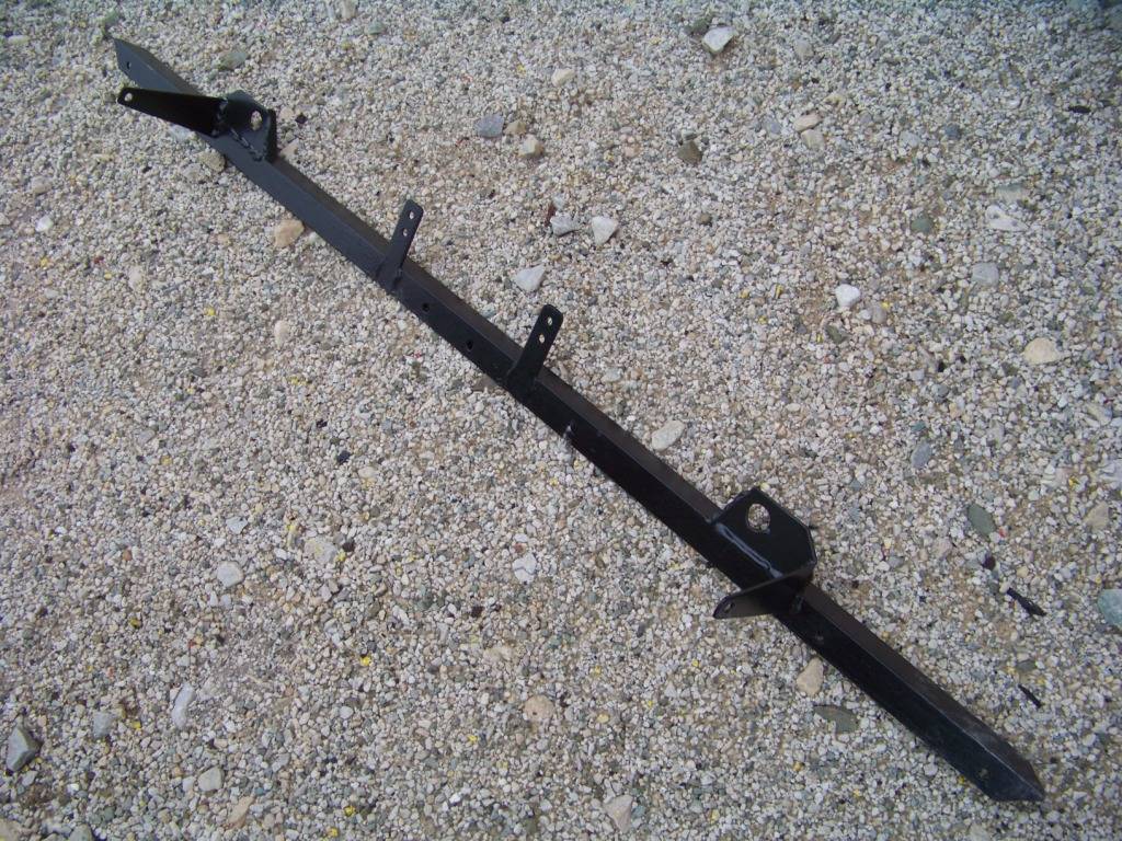
- 58
This post will document the transmission crossmember I made. I first tried to modify the Pontiac cross member but found it wouldn't have been feasible. I also considered buying a Chevelle cross member and doing the easy typical mod of flipping and re-welding the tab on, but didn't want to spend the money for a new one or spend time looking for a used one.
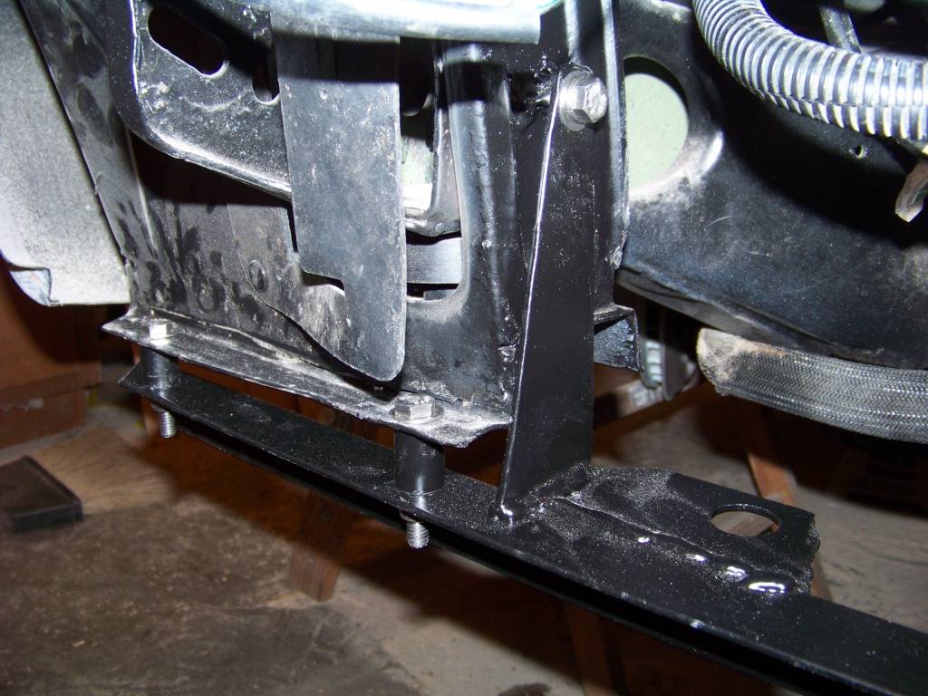
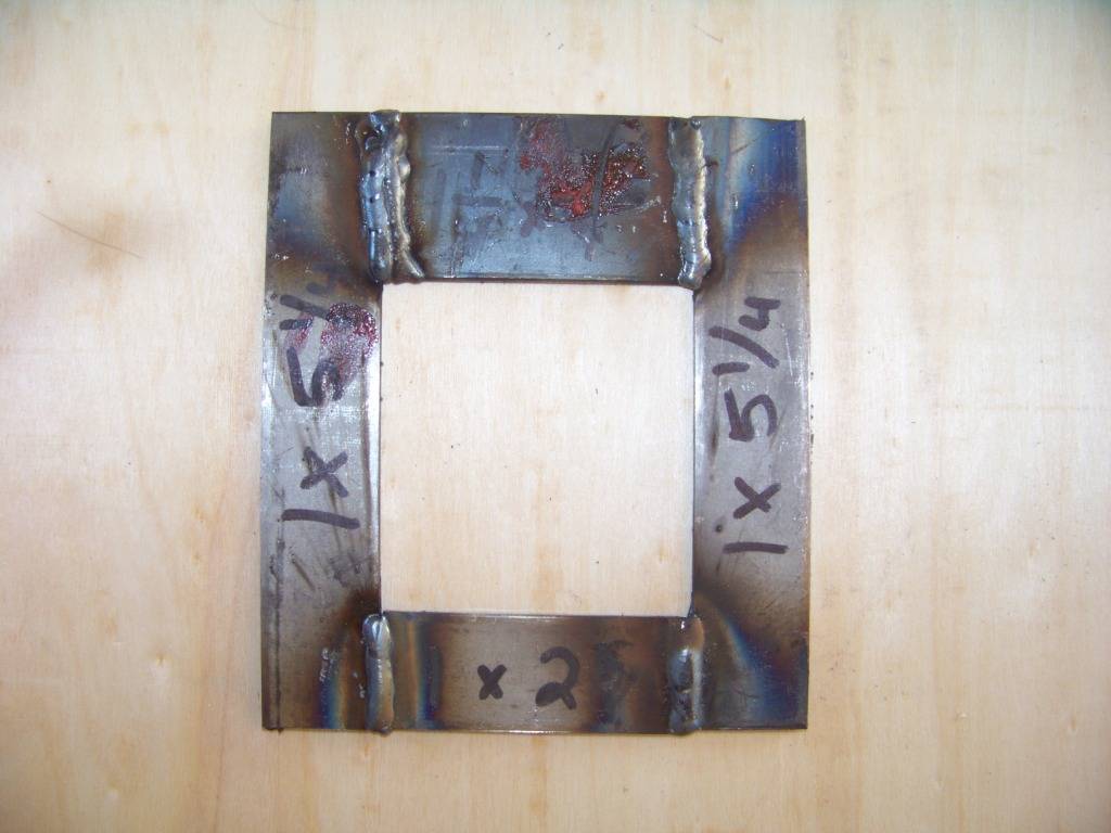
I was getting more comfortable with my welding skills so I decided to give this a go. I used metal angles and straps I found at Lowes. I decided to make it in three pieces, two small brackets that sit on top of the frame and the main cross member part. Height adjustments for driveline angles will be done between the frame brackets and main cross member.
The brackets are in the shape of a "Z", I tried to add strengthening braces to all parts as much as I could.
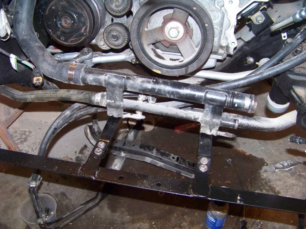
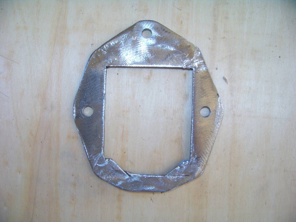
The main cross member was made of several pieces, here are views looking forward and aft:
Not the prettiest thing in the world, but hopefully it works for awhile. Someday I will probably make another one that looks better.
Now next will be headers and exhaust.
09-03-2012 #8
Registered User
- Join Date
- Nov 2011
- Location
- Springfield, OH
- Posts
- 58
As promised some info on the headers and exhaust:
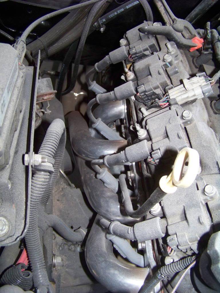
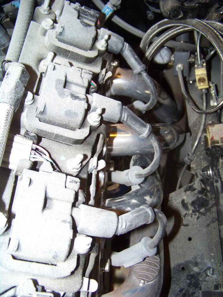
After doing my usual "exhaustive" research I decided on Doug's LS1 swap Headers for A-bodies. I bought part number D3338, the ceramic coated ones. Amazon actually caries these, so I got a pretty good deal and free shipping. Inside the package was the headers, gaskets, bolts, 3" to 2 1/2" reducers, two clamps, and two O2 sensor extension harnesses. The headers have O2 bungs welded on the outside of each collector. They come wrapped in bubble wrap which I left on during installation to avoid scratches and dings. I installed these before the body went back on so they went on pretty easy.
These fit great in my situation, I have plenty of clearance everywhere. I should mention that I did move the brake distribution block from it's normal position on the inside of the frame to the top of the frame below the master cylinder, you can see that in the driver's side picture below. I knew from my research that this was a possible issue and it didn't really bother me too much as I was running new lines anyway and also adding an adjustable proportioning valve nearby.
One issue that I did have to deal with is that the O2 extension harnesses supplied by Dougs would not work with the engine wiring harness from the 04 GTO, apparently they use different connectors (square gray) than the F-body LS1 harnesses (square black). I did call Dougs about it and was just told to go buy the correct ones. I found and ordered the correct ones on ebay, they seem to work fine.
Another issue I had was that the original GM spark plug wires didn't fit very well around the header tubes in some cases. I decided to get a set of MSD -32813 spark plug wires, these have bendable spark plug boots so you can position the boot wires away from the headers as needed. These are also shown in the pictures below.
Here are pictures of the headers: Excuse the dust, been busy making cabinets lately and the dust goes everywhere.
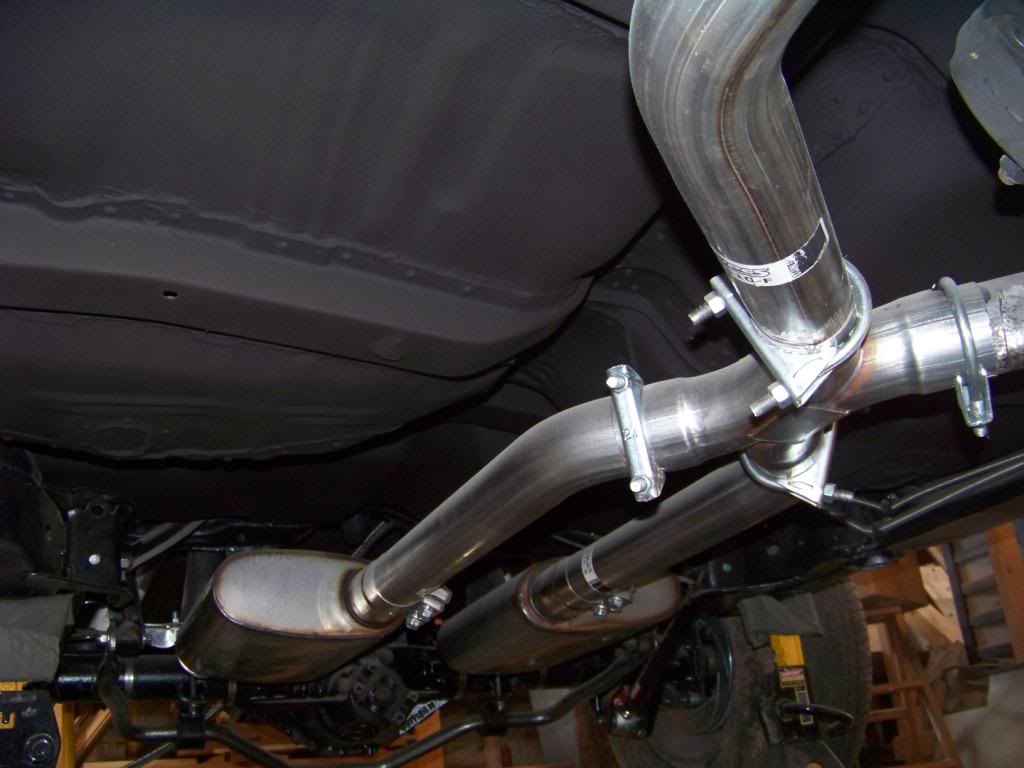
For exhaust I decided to go with the Pypes 2 1/2" system with x-pipe, part number PYE-SGA12S. I chose these because they seemed to have a fairly good reputation and are stainless steel for a reasonable price. The system comes with stainless hangers that are the same design as the original GM hangers. This system did require some mods to install, I end up trimming the four pipes forward and aft of the x-pipe as necessary to get everything to fit.
The Pypes kit comes with standard u-bolt style clamps, I did end up replacing some of these with stainless band clamps I got from Summit, part number WLK-33226.
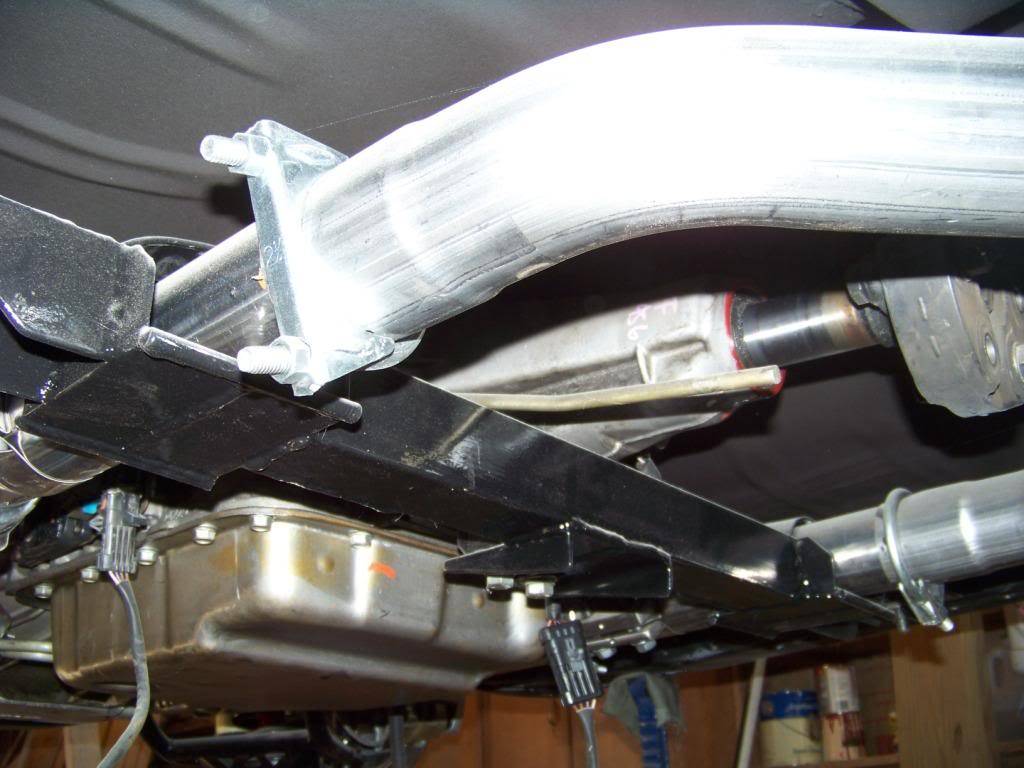
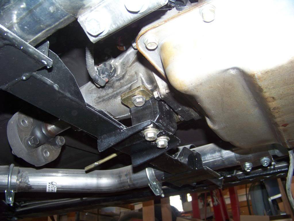
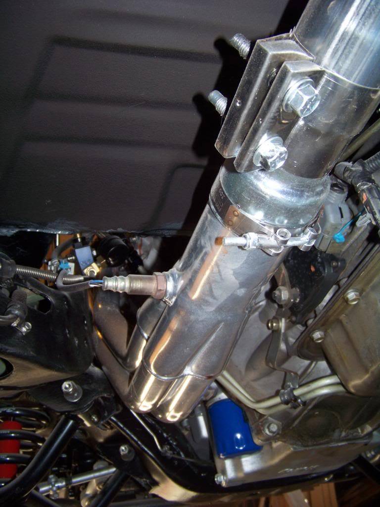
This picture shows the driver's side header from underneath the car. You can see there is plenty of clearance between the header and floor, frame, and other parts. Also plenty of room to install the O2 sensor. The Pypes clamp was used to attach the reducer to the header collector and the band clamp I bought was used to attach the reducer to the exhaust. You can also see the Holley LS1 swap oil pan in this picture and how well it fits flush with the bottom on the engine crossmember.
The picture below shows the x-pipe and mufflers installed. I positioned the clamps in such a way to avoid damage from speed bumps and to make the bolts accessible in the future.
Now that I have installed as much as I can on the frame I can put the body back on, that will be the next update (the above pictures were taken after that).
10-21-2012 #9
Registered User
- Join Date
- Nov 2011
- Location
- Springfield, OH
- Posts
- 58
Next step was to put the body back on the frame.
I just reversed the procedure when I removed the body - we rolled the rolltisserie back to horizontal and supported the body again with the concrete blocks and 2x4s as before. At this point the rolltisserie was removed from the body. The frame was rolled back under the body and I lowed the body back onto the frame, doing it gradually removing a 2x4 spacer at each corner at a time so the body wouldn't get twisted. As I got closer I lined up the frame under the body so the body bolt holes would line up.
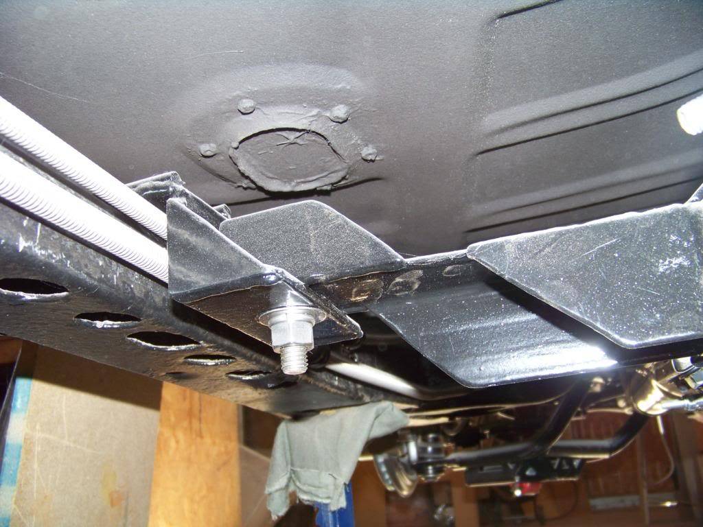
When I removed the body from the frame most of the cage nuts were rusted to the point where they either broke or I had to cut through the bolt. I don't particular care for this GM design where the nuts were hidden in body cavities the way they were, if the body were ever to be removed again I wanted the process to be easier. I also wanted to use stainless fasteners as much as possible and cage nuts don't come in stainless. Here is what I came up with.
In most locations I drilled 1 1/2" holes through the sheet metal floor directly above the bolt locations. I did this by first drilling a small pilot hole through the sheet metal floor from the bottom through the larger body hole in the floor brace while the body was rotated on the rolltisserie. I then drilled the 1 1/2" hole from the top through the floor using a bi-metal hole saw. I bought 7/16" stainless bolts of varying lengths along with stainless nylon lock nuts and large stainless fender washers. I also used new rubber body mount bushings I bought from OPGI, and used the cone washers that came with the kit but not the bolts.
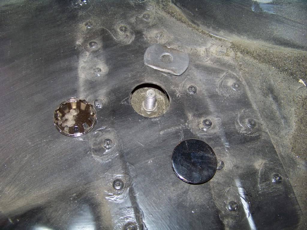
I had to trim the upper washer as shown so it would fit through the 1 1/2" hole in the floor. I was able to reach all of the bolts and nuts to tighten them by myself except the ones under the trunk hinges, those need two people to do. The hole in the floor will be covered up with the 1 1/2" diameter chrome cap, which is a standard item in the blue hardware drawers at Lowes. I will just run the Dynamat over these covers.
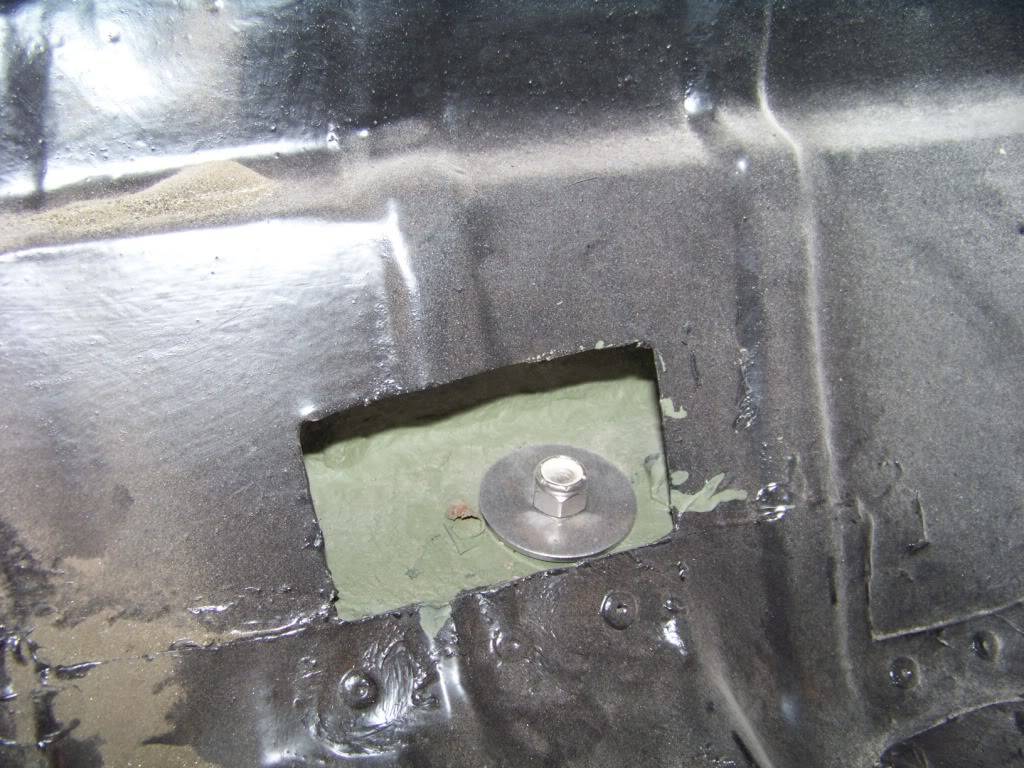
The most rear mounts were a little different situation due to where they were located. I cut a square hole in the area in the trunk to access the cavity to install the washer and nut. I will make a overlapping cover panel which will be painted and installed with stainless screws and sealant. Cutting these holes also allowed access to spray the cavity with internal frame coating.
10-23-2012 #10
Registered User
- Join Date
- Nov 2011
- Location
- Springfield, OH
- Posts
- 58
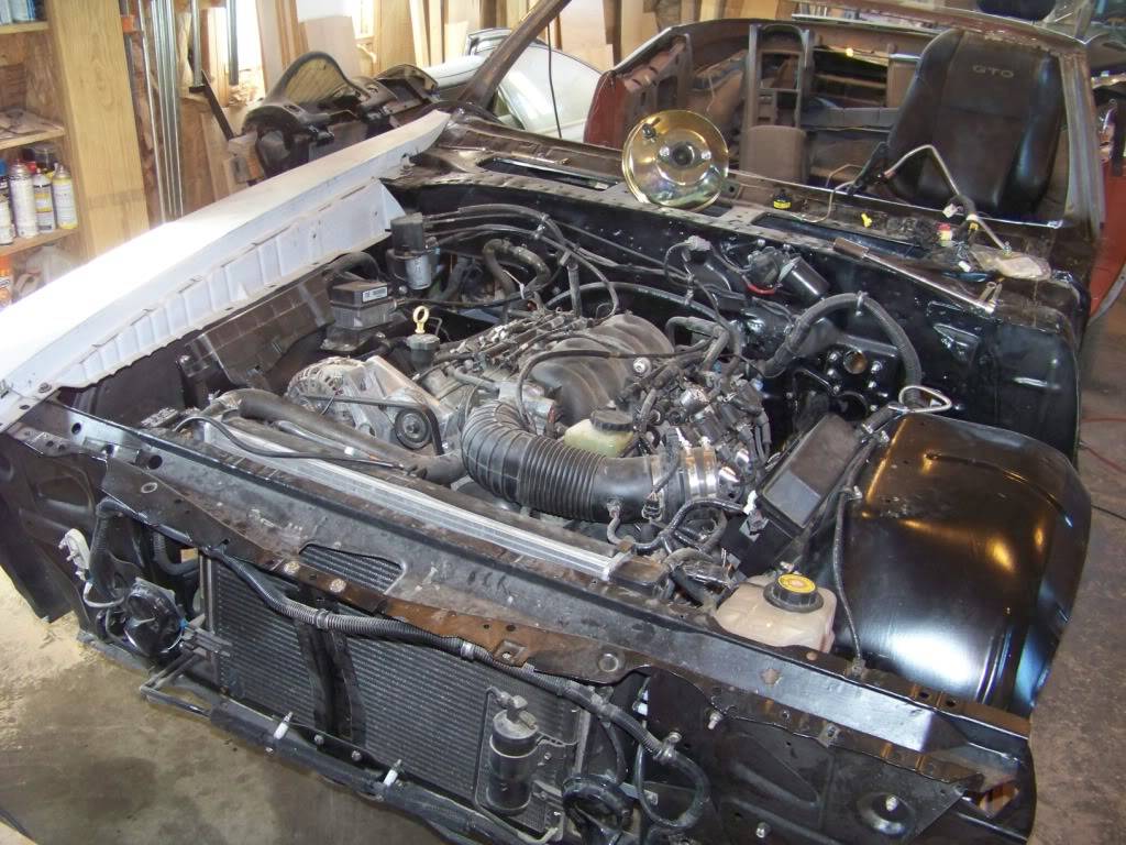
Once the body was back on the frame I was eager to get the engine started as most of you would. So that meant I needed to get a lot of things installed in the engine bay.
I noticed on the new GTO a lot of components were mounted on the inner fenders. I wanted to move things over as simply as possible so I figured I would reinstall these components in similar locations on the Lemans. I didn't want to rework the harness and possibly create a lot of headaches so that's why I was compelled to use the existing component locations as much as possible. I had previously blasted, primed and painted the inner fenders in preparation for this time so I went ahead and installed them. I also installed the radiator core support and passenger fender to help support it. I am going for a factory look here, as if GM would have built a 71 Lemans with 2004 technology.
On the new GTO the underhood fuse panel and cruise/throttle cable components are mounted on the passenger inner fender. These pictures shows how I mounted these. I made brackets as required and attached everything through existing or new holes in the inner fender with stainless bolts. When placing components I kept in mind that the associated connectors on the wiring harness had to reach the components so I laid the wiring harness over the engine bay as I did this process.
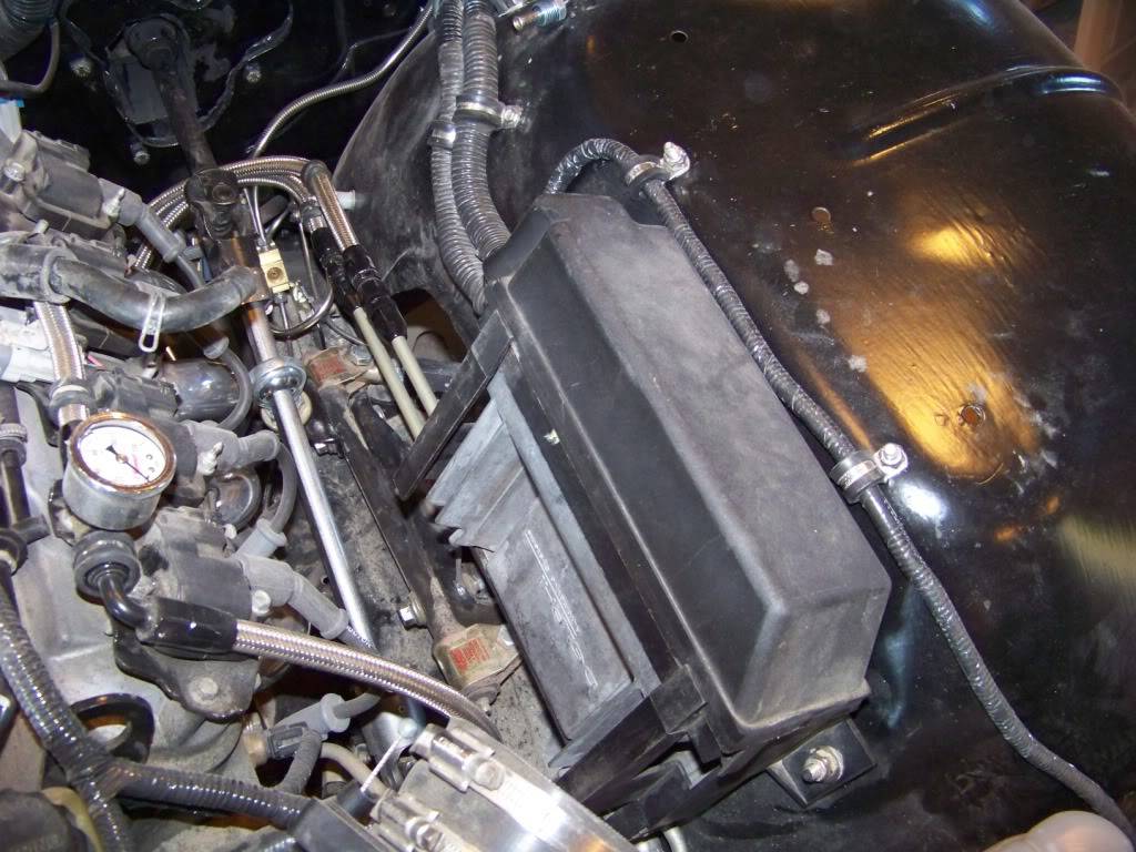
This picture shows the mounting of the underhood fuse panel.
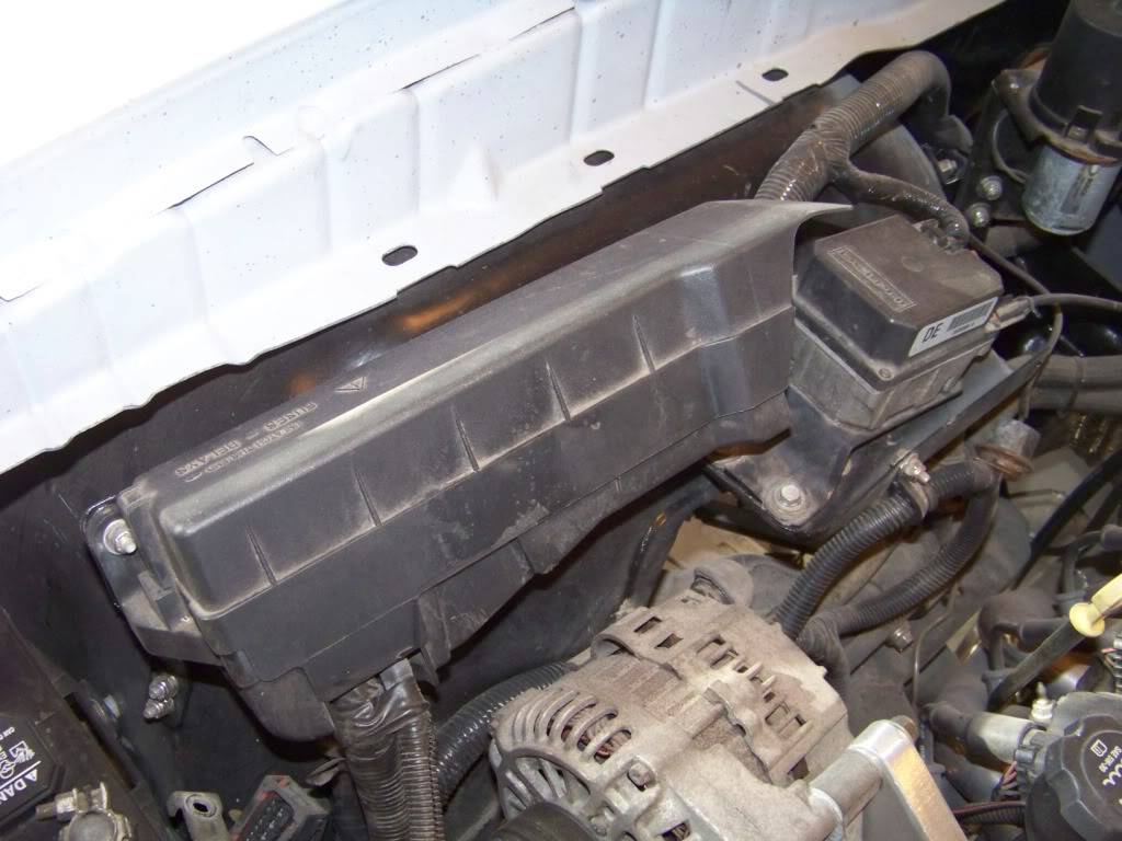
The fuse panel attaches directly to the inner fender on the back side, the forward side needed a bracket I made to support it:
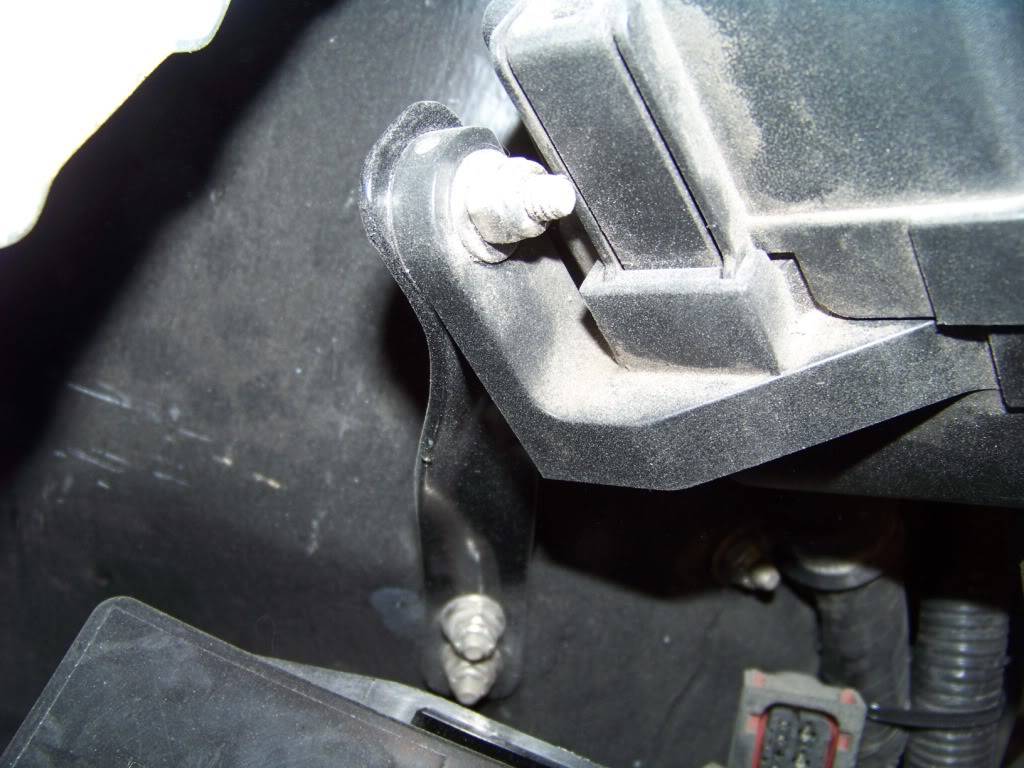
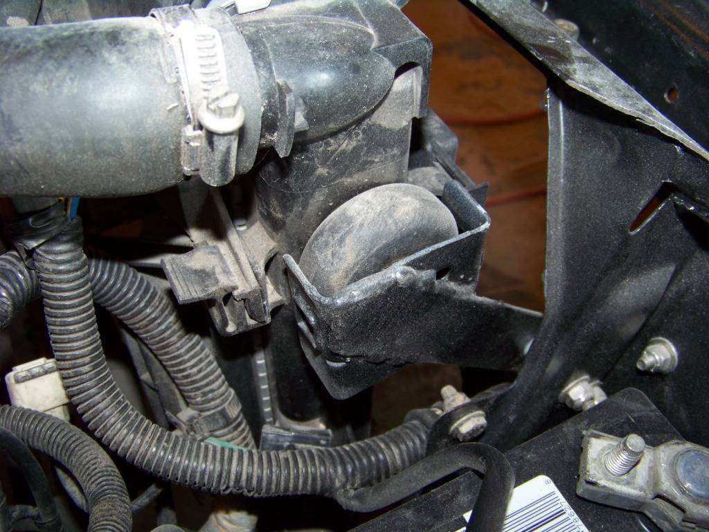
This picture shows the mounting of the cruise and throttle cable components.
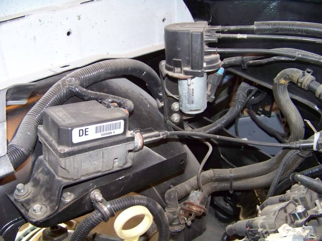
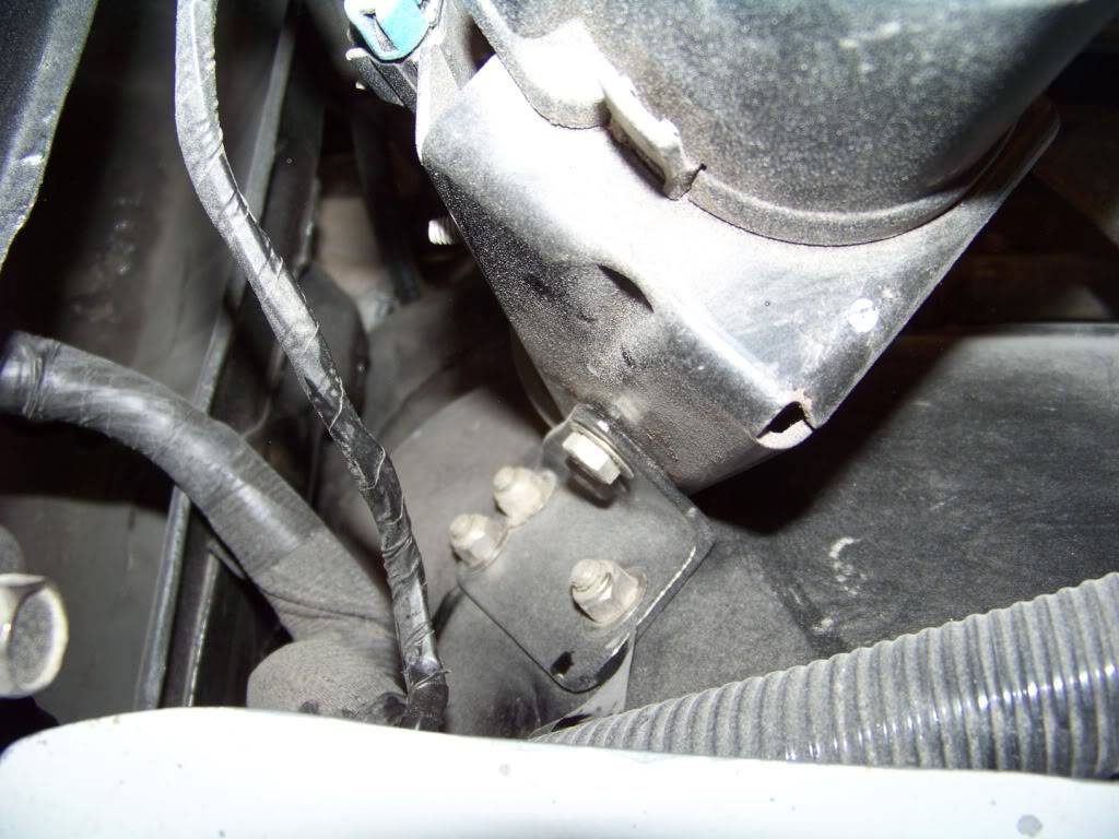
I am not sure exactly what these components are, I assume the forward box shaped item is the cruise servo, the rear cylindrical thing is where all the cruise and throttle cables come together. For the cruise servo I cut the supporting bracket from the GTO donor and mounted it with a supporting bracket underneath that I made.
For the cable component I made a bracket from some angle to support it on the inner fender, this is a view looking down, forward is to the right:
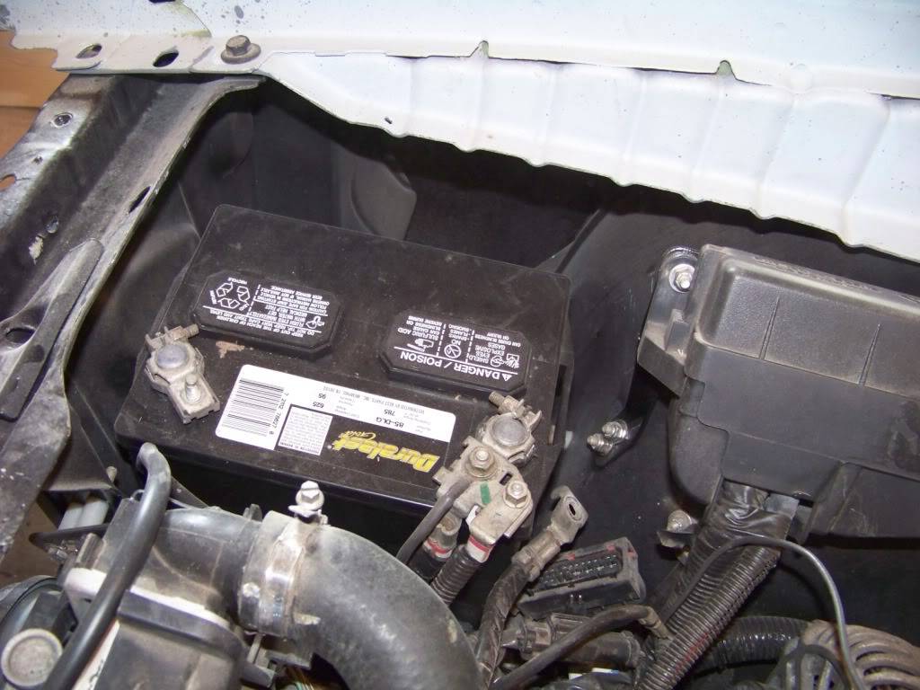
On the new GTO the battery is located on the passenger side just behind the headlight. I was at a car show a few months ago and noticed on Pontiac A-bodies the battery is on the drivers side and on Chevelles the battery is on the passenger side. To keep things the same as the new GTO I mounted the battery on the Chevelle or passenger side. Since my GTO donor didnt come with a battery I got a new one from Autozone. I got the correct battery for the new GTO, it fits in the a-body location just fine.
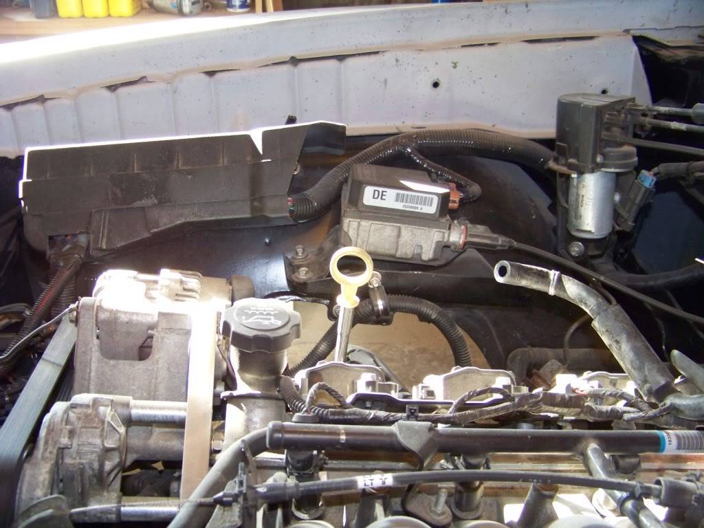
On the new GTO the ECM is mounted on the lower drivers inner fender just above the frame rail. Again, I picked a similar location although I moved it up to get it away from the header. The ECM is mounted in a plastic holder with a cover. I just used the holes in the holder to locate new holes in the inner fender.
10-25-2012 #11
Registered User
- Join Date
- Nov 2011
- Location
- Springfield, OH
- Posts
- 58
Alternator Relocation
As I mentioned in a previous post I decided to relocate the alternator after I discovered it would interfere with the steering gearbox. I looked into the different kits on the market to accomplish the task but didnt want to spend the money. These kits start at about $150 and go into several hundreds for the fancy kits with polished parts and such. For this project I am more interested in function than form so I set about making my own mount.
I decided to relocate the alternator up high on the passenger side. This brings it up closer to the battery and underhood fuse panel. I think it would have been tougher to put it high on the drivers side with the existing power steering pump.
The alternator was originally mounted on the front of the block down low on the drivers side. It appeared to me that the front of the drivers side head was on the same plane as the front of the block, and I researched and found out that the passenger side head is offset to the rear about 0.75 inch. So I decided to base my bracket on a 0.75 think aluminum plate figuring that would put the alternator roughly in the same plane again. I went through several designs using ¾ particle board until I had a design I was happy with. I actually spent more time fussing with the tensioner relocation trying to get the proper leverage to tension the belt. This bracket relocates both items.
Below is a drawing with dimensions of my bracket. I made it from a 8 inch by 8 inch by 0.75 inch aluminum plate that I bought from McMaster for about $39 (part number 9246K51). At the time I didnt have access to a machine shop so I cut this plate with a reciprocating saw and finished it with belt and spindle sanders. Crude, but I got it done.
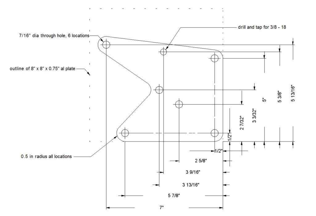
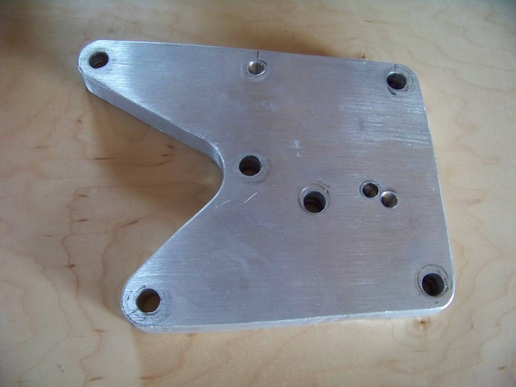
Disregard the two holes right next to each other, they were from an earlier unsuccessful attempt to relocate the tensioner bracket.
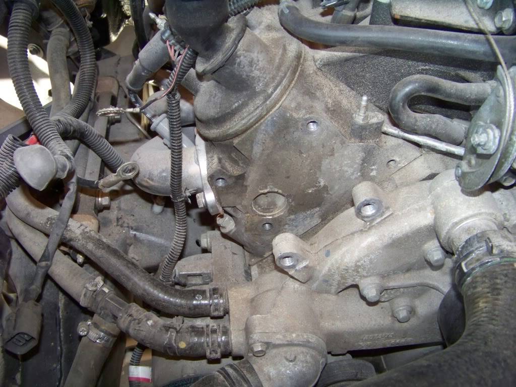
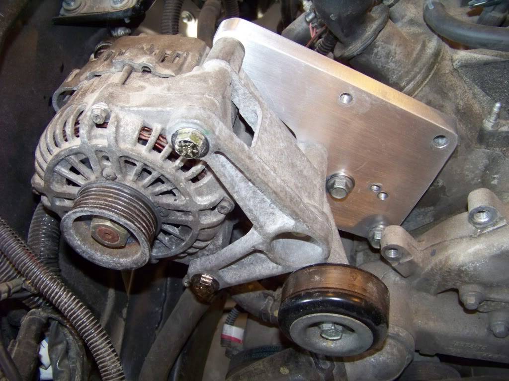
The picture below shows where I mounted the bracket. I am using the three outer holes on the front of the passenger head. The fourth most inner hole is not used. In this picture you can also see the two holes just below on the water pump that used to support the tensioner bracket.
The bracket is mounted to the front of the passenger side head with M10-1.5 x 40 bolts as shown below. The holes in the head are already tapped to that thread size.
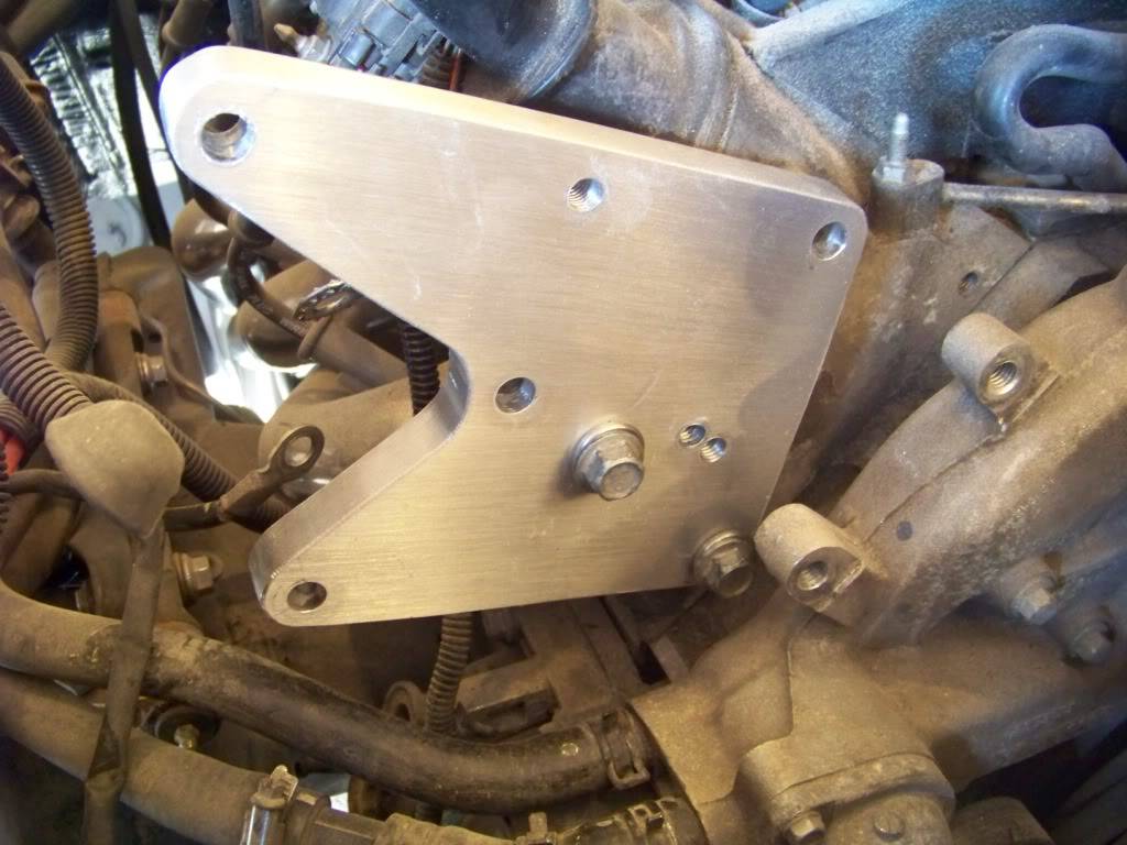
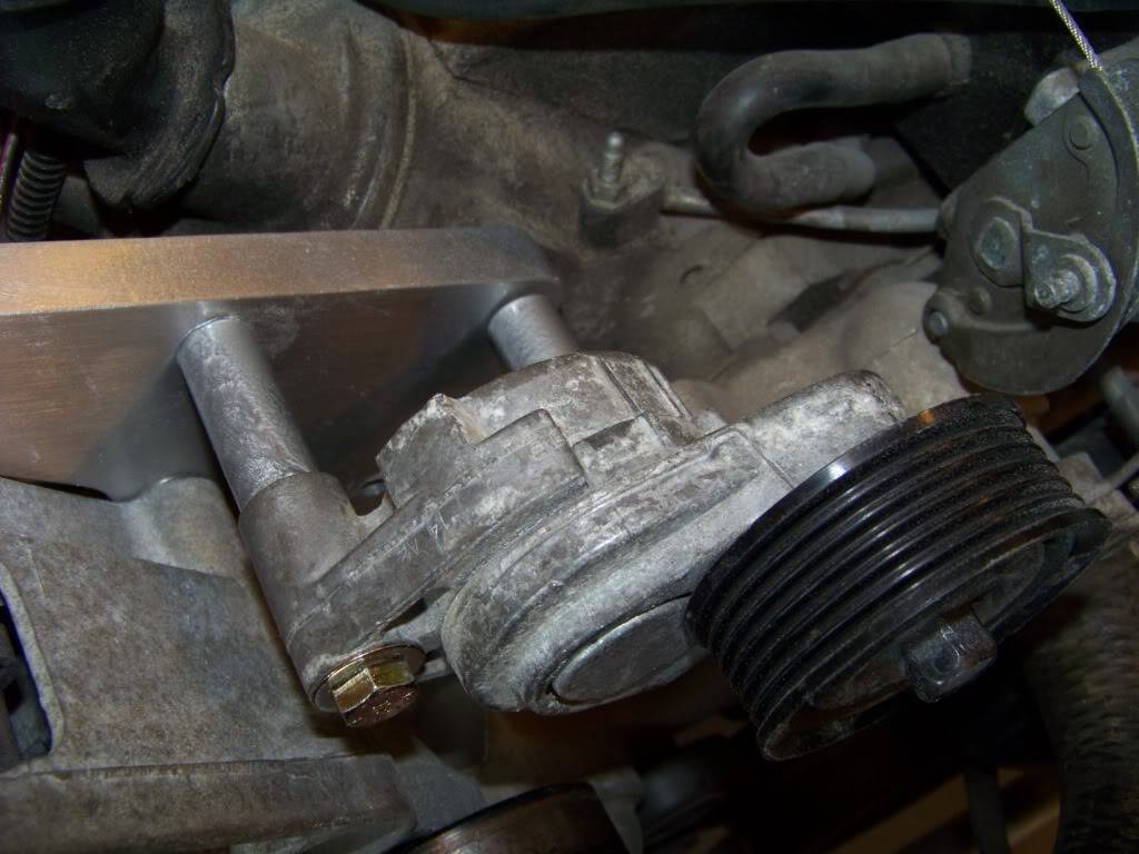
The alternator is mounted to the bracket with two 3/8 x 5 1/2 in. bolts and one 3/8 x 4 1/2 bolt, I used grade 8 bolts.
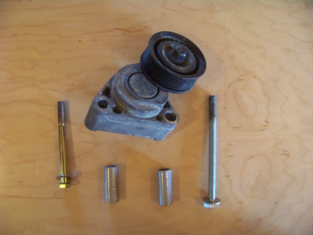
The tensioner is mounted with one M10-1.5 x 130 bolt in the inner hole, this bolt goes through the hole on the bracket and into the existing hole in the head. The outer bolt is 3/8 x 4 and threads into the bracket. To keep the tensioner aligned with the other pulleys it is installed with spacers between the alternator bracket and the tensioner bracket. These spacers, made from 1/2" pipe or heavy conduit, are 1.70 inches long.
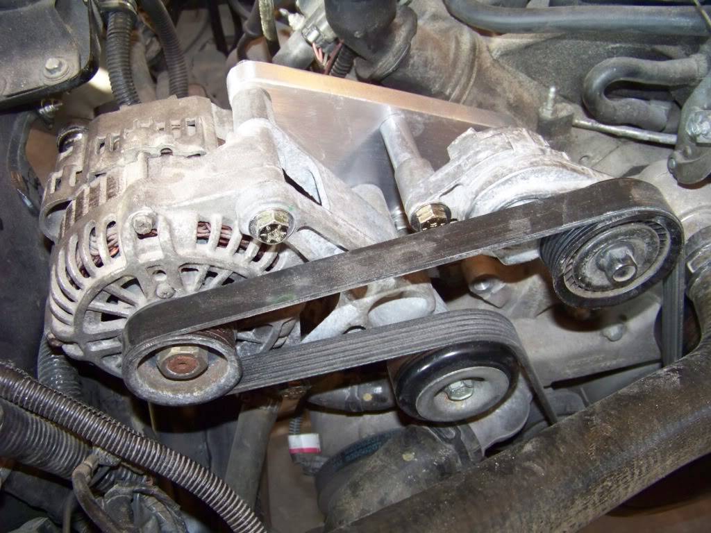
I put a straightedge across some of the pulleys to make sure they were in the same plane, I did put one washer between the alternator and bracket at each of the three bolt locations to get the pulleys in the same plane.
For the belt I tried measuring with a string and then a metal tape measure wrapped around all of the pulleys but that only got me a starting point for belt length. From there it was a trial and error process of getting belts from the auto parts store and trying different ones until one worked well. For this particular installation that ended up being a Gates K060815 belt (six ribs, 81.5 inches long). This belt fits pretty snug, the tensioner is at the higher end of its scale.
The bracket seems very sturdy and I have run the engine several times without issue, although not at full throttle yet.
10-26-2012 #12
Registered User
- Join Date
- Nov 2011
- Location
- Lowell MI
- Posts
- 50
That's a nice bracket!
12-01-2012 #13
Registered User
- Join Date
- Nov 2011
- Location
- Springfield, OH
- Posts
- 58
An update for my build thread for those of you who may have wondered what's happening . . .
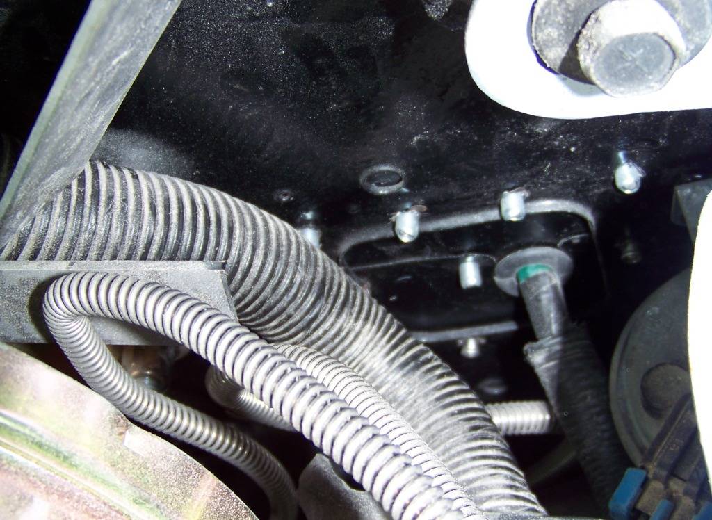
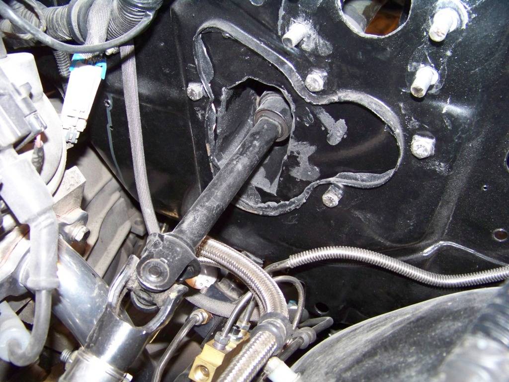
Transmission Cooler Lines
Obviously the transmission cooling lines from the GTO donor werent going to fit exactly into the Lemans, but I did manage to use most of them. I cut a small section out in each line from where they went around the drivers side header and joined the lines with some AN fittings and braided hose. The fittings I used were -6 AN 3/8 hard tube fitting adapters (part number SUM-2200077B at Summit, four required) for the cut ends of the tubes and -6 AN straight hose ends (part number SUM-220690B, again four required) and two appropriate lengths of -6 AN hose.
I thought about doing the whole thing in AN lines, but it would have been a lot more expensive due to the special adapter fittings required at the radiator and transmission.
This picture also shows the steering linkage which I hope to discuss soon when I get into the interior installation.
12-01-2012 #14
Registered User
- Join Date
- Nov 2011
- Location
- Springfield, OH
- Posts
- 58
Cooling System
I was determined to use as many components from the GTO donor as possible and that included the cooling system. The new GTO radiator is slightly taller but several inches narrower than the opening in the Lemans core support. The GTO radiator apparently just sits in its core support by gravity. So I duplicated how it was mounted into the Lemans. Two posts with rubber bushings protrude from the bottom of the radiator and rest in corresponding holes (upper right below) in the bottom of the new GTOs core support, see picture below.
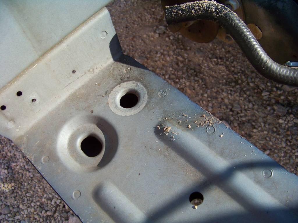
I drilled matching holes in the bottom of the Lemans core support as shown. In the picture below I am using a screwdriver shaft to hold the radiator up so you can see how it rests into the new holes. Excuse the dust, woodworking and car building don't mix very well.
On the outside upper edges of the radiator are rubber doughnut shaped bushings. These slide into u-shaped brackets attached to the core support. These u-shaped brackets were removed from the GTO donor and modified to fit into the Lemans. I welded straps to the u-shaped supports and mounted them on the Lemans core support with bolts, and nylon spacers.
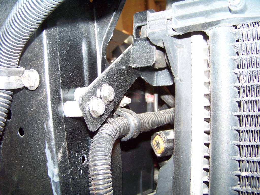
I noted the Lemans core support leaned forward slightly at the top. I used this to my advantage when I mounted the new GTOs radiator. It sits in the new holes in the bottom of the core support and raises above and behind the core support at the top so the radiator ends up being fairly vertical. I am not sure whats going to happen at the top of the core support, I removed the upper sheet metal panel when I reworked the core support. The sheet metal will have to be trimmed, and I may come up with a radiator cover at some point.
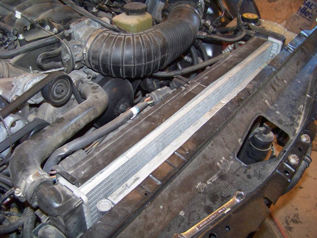
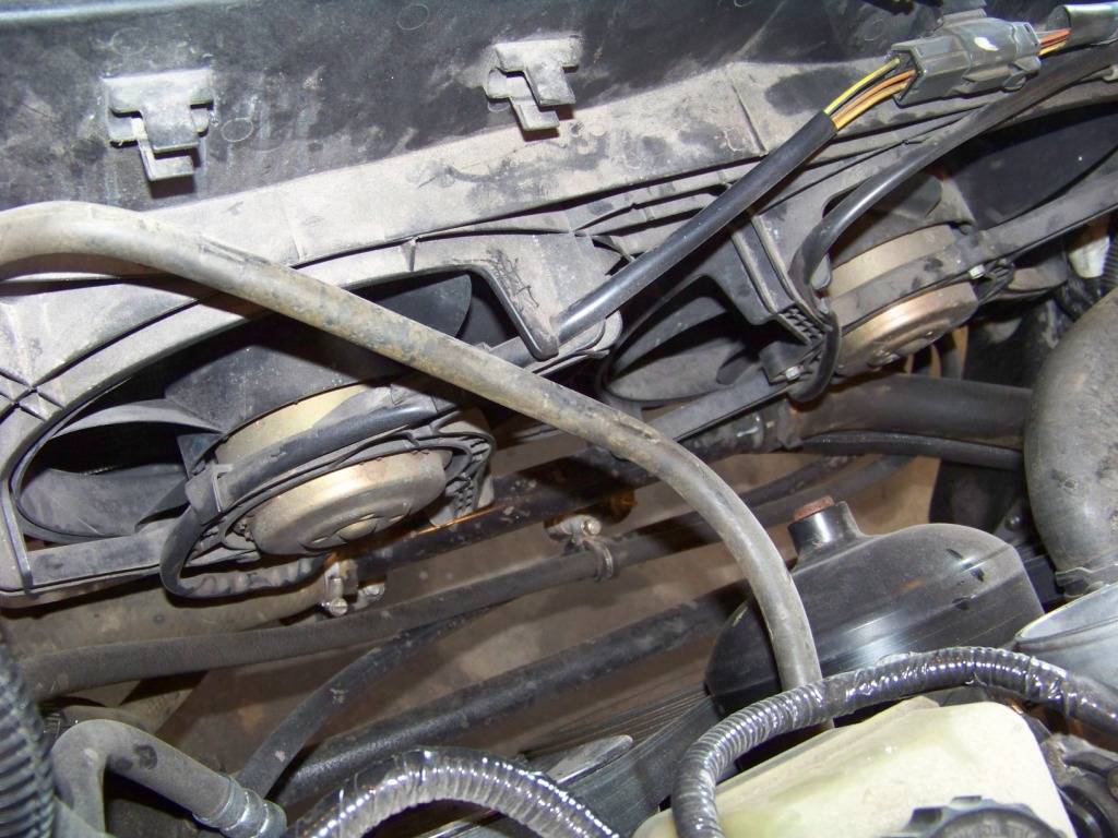
By the way, the AC condenser and electric fans were reinstalled onto the radiator just as they were on the GTO donor. It was easy-peasy because they both attach directly to the radiator so there wasn't any fabrication to do. They both just slide down onto L-shaped brackets on the radiator and snap into place. There is ample room in front and behind the radiator for these components.
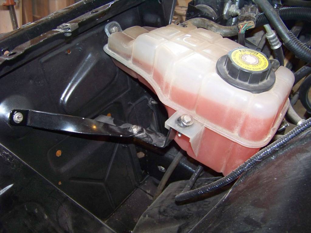
This last picture shows the installation of the coolant recovery tank. My original thought was to get his mounted in a drivers side location in such a way that all the connections would route well to mating components. But I have since discovered that I may have mounted it to low, which is important as I believe the tank helps determine the level of the coolant in the system and mine is therefore may be too low. I will be looking into ways to remedy this issue.
As far as hoses go I was able to use all of the existing radiator and heater hoses from the GTO donor. This will just make things that much easier when I go to the parts store for replacements, I just tell them it's for a 2004 GTO.
02-02-2013 #15
Registered User
- Join Date
- Nov 2011
- Location
- Springfield, OH
- Posts
- 58
Cooling System Rework
As I mentioned in my previous post about the cooling system, I discovered that I probably originally installed the coolant recovery tank too low. This post shows how I remedied that.
I tried in vain to figure out a way to raise the tank enough, but I wasnt successful. The only other place I could think of was higher up on the inner fender where the ECM was, but then that means I would have to find another place for that and I was happy with where it was. Then it occurred to me that I could lower the radiator. I ended up doing that and raising the coolant recover tank.
I cut the center part of the lower channel from the core support and made a new lower radiator support from angle iron and tabs welded on as required to support the GTO radiator.
This new support was attached with bolts and spacers to the bottom on the core support as shown. This ended up lowering the radiator about 2 3/8 inches. As a bonus, the radiator no longer sticks up above the top of the core support. The top support brackets for the radiator were also moved down an equal amount. The picture below shows the attachment of the new lower channel on one side, the other side is just the opposite.
The picture below shows the support and installation for the coolant transfer tubes between the lower part of the radiator and the engine. This assembly was on the GTO so I also moved it over so I could use the GTO's lower hoses.
The coolant recovery tank was reinstalled in approximately the same position it was before except about 2 inches higher. The picture below shows the support brackets I fabricated and installed to support the tank. This is looking down into the area between the driver's side inner fender and the core support. The brackets are attached to the inner fender and core support. The bracket in the lower left corner of the picture is simple flat support the recovery tank rests on to support it.
The following picture shows the recovery tank installed. The tank is now higher than the radiator and engine so the system should be filled correctly in the engine and radiator.

As part of this effort since the cooling system was drained I got the HVAC system installed in the interior and connected all of the heater hoses. I will document that in a future post.Last edited by fsdproject; 02-02-2013 at 08:38 AM. Reason: Added picture and text for coolant transfer tube supports
02-02-2013 #16
Registered User
- Join Date
- Nov 2011
- Location
- Springfield, OH
- Posts
- 58
Firewall Interior Side Part One
I wanted to finish up the cooling system, which meant getting the HVAC system in, which meant getting the GTO's dash into the Lemans. But first I wanted to make sure everything needed was routed through or attached to the firewall, it's much easier to do before the dash goes in.
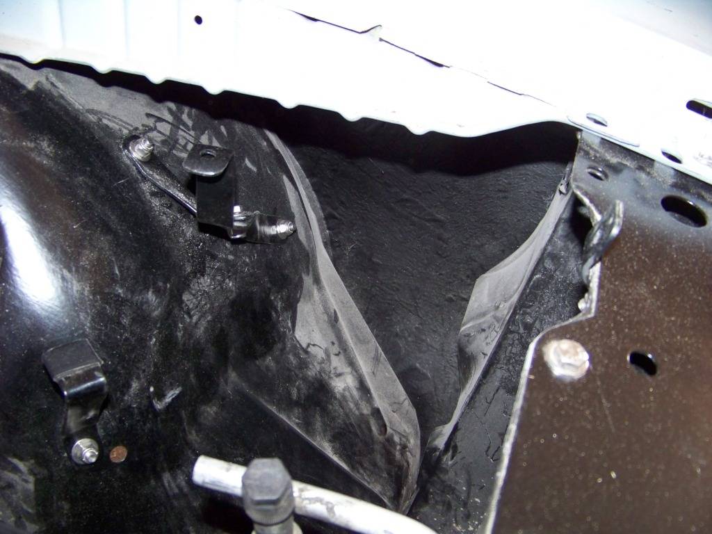
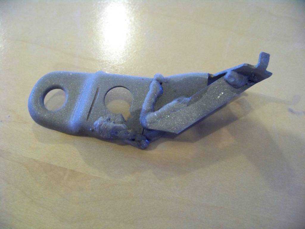
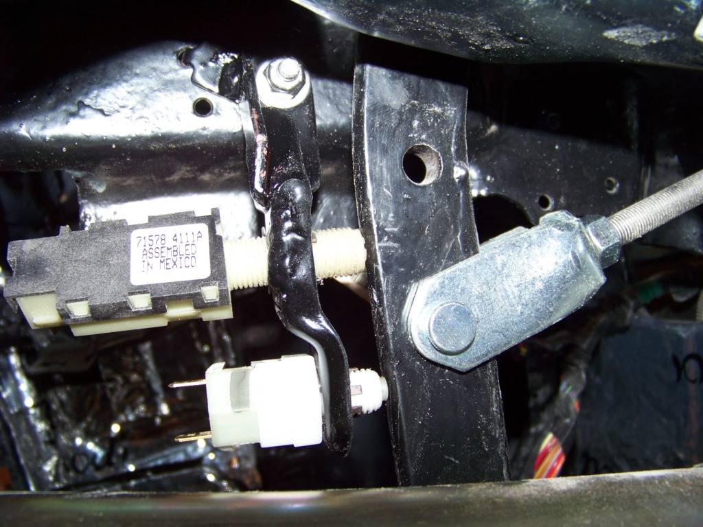
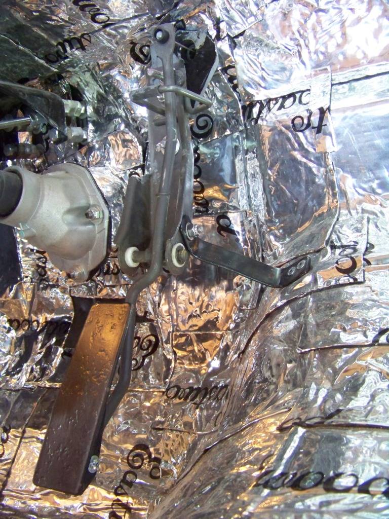
Brake Pedal
I used the brake pedal and support bracket from the Lemans. The only change I did here was to move the bracket a couple of inches rearward to accommodate the deeper size of the GTO dash. I just did this by using longer bolts and oversize nuts as spacers. The threaded rod from the brake booster was lengthened accordingly. I unfortunately did not take a picture of this. The GTO had two switches on the brake pedal, the Lemans had one. Interestingly, the main brake switch on the GTO appeared to be exactly the same as the one I took from the Lemans. I guess GM uses the same switch 30 plus years later. I did need to support both switches onto the Lemans' bracket, I just welded the lower portion of the GTO's brake switch bracket to the upper part of the Lemans. The pictures below show the modified bracket welded together and installed.
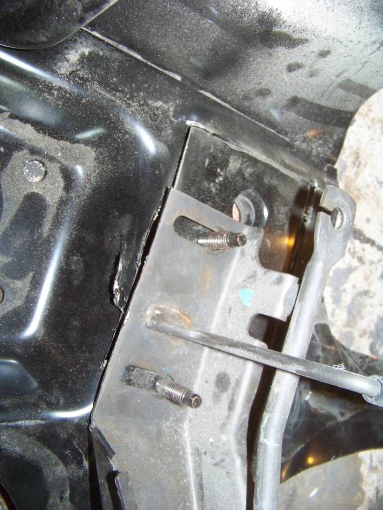
Gas Pedal
I wanted to use the GTO's gas pedal assembly because it was already designed to work with the throttle cable from the engine. The picture below shows how the gas pedal assembly attached to the GTO's firewall. I needed the round opening in the firewall above the bracket to support the cable end so I cut that portion out as shown.
The assembly of the firewall section and the gas pedal assembly was bolted to the firewall in the appropriate place. I added the black bracket as shown to support the lower portion of the pedal assembly. I also thought the gas pedal was too low so I created a new one from welded steel with the pivot point towards the bottom instead of the middle, although I may go back to the GTO's pedal as a play around with things in the interior. In the upper right corner of this picture you also can see how I spaced the brake pedal bracket from the firewall.
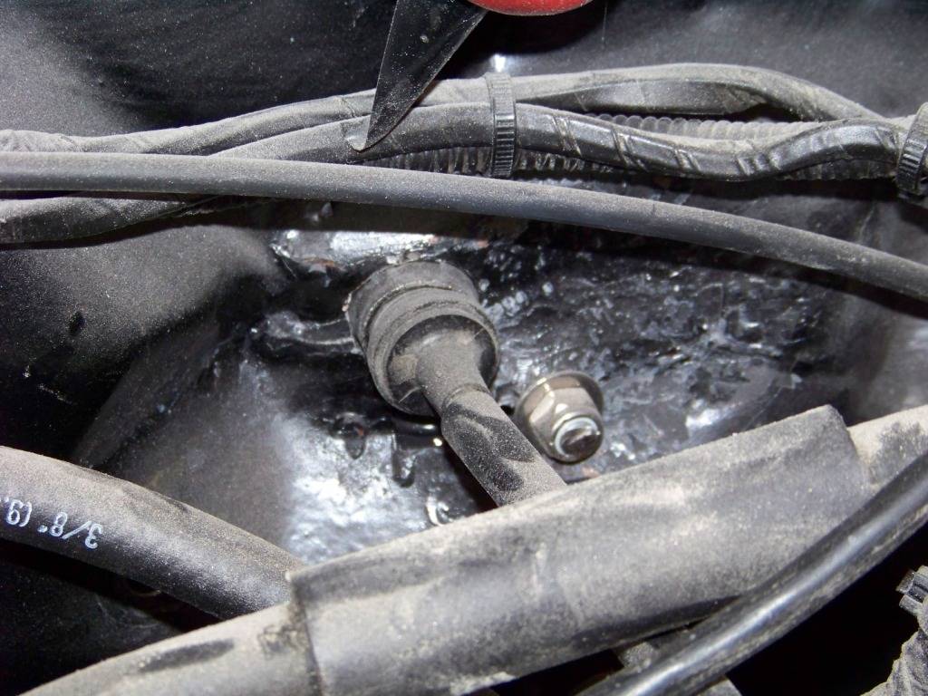
I drilled a 1" dia hole in the Lemans' firewall for the cable end support from the GTO firewall. The picture below shows that on the forward side of the firewall.
Cowl Vent Covers
Since the GTO's HVAC takes fresh air from the upper cowl area, these large openings in the lower sides on the cowl are no longer needed. I made up some simple sheet metal covers and riveted them and sealed them in place on both sides. These were then covered up with sound deadener material.
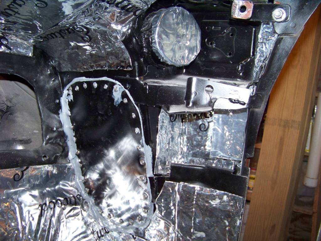
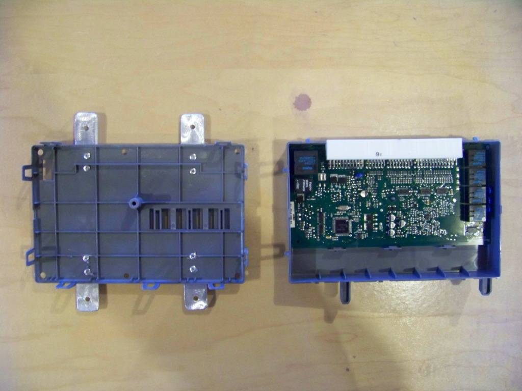
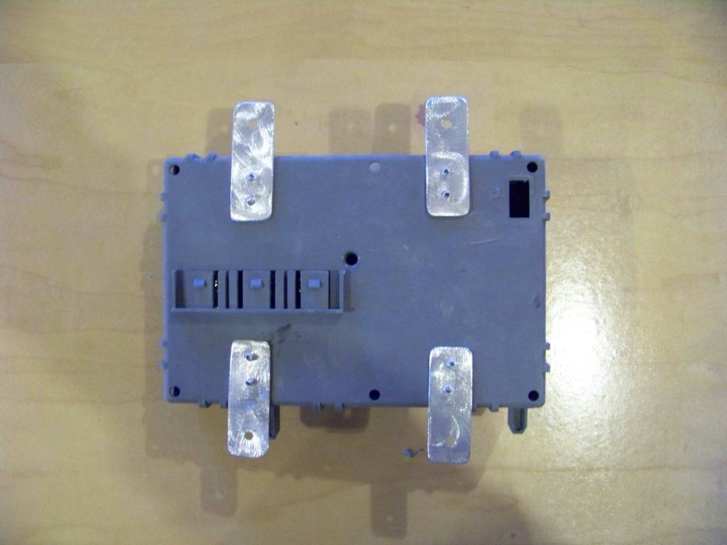
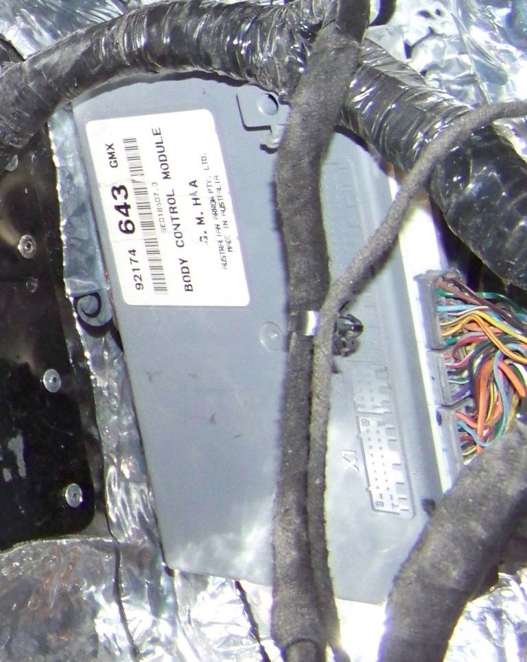
BCM Installation
On the GTO the BCM is installed on the interior side of the cowl pasenger side, I did the same. I did a similar thing on the driver's side with the throttle control module. The pictures below shows adding brackets to the BCM, then the BCM attached with sheet metal screws through the new brackets to the cowl cover plates discussed above.
Firewall Part Two will cover wire bundle and HVAC routing through the firewall.
02-02-2013 #17
Registered User
- Join Date
- Nov 2011
- Location
- Springfield, OH
- Posts
- 58
Firewall Interior Side Part Two
I then needed to get two wire bundles and four HVAC connections through the firewall.
Driver's side wire bundle
A smaller wire bundle from the GTO donor goes from under the hood to the dash area on the driver's side. I used the existing rectangular hole in the firewall that was originally used for the fuse block and connection to the Lemans' wire bundle. I needed to find a way to seal the opening around the existing hole. There are existing split seals available, but they didn't really work well for this situation. I did use their design concept in what I came up with.
I made a two-piece cover that could be installed around the wire bundle which was already routed, I didn't want to remove all of the connectors just to route it through a grommet. The cover is made from sheet metal, the grommet is just an appropriately sized rubber grommet I got from Lowes. I cut the grommet in half and put each half into each half of the cover plates. The two plates overlap each other in the middle to sandwich the grommet halves together.
This picture shows the plate/grommet assembly installed from the front of the firewall. The plates are attached to each other and to the firewall with 3/16" steel rivets, the plate will be sealed with seam sealer on the outside and covered with sound deadener on the inside.
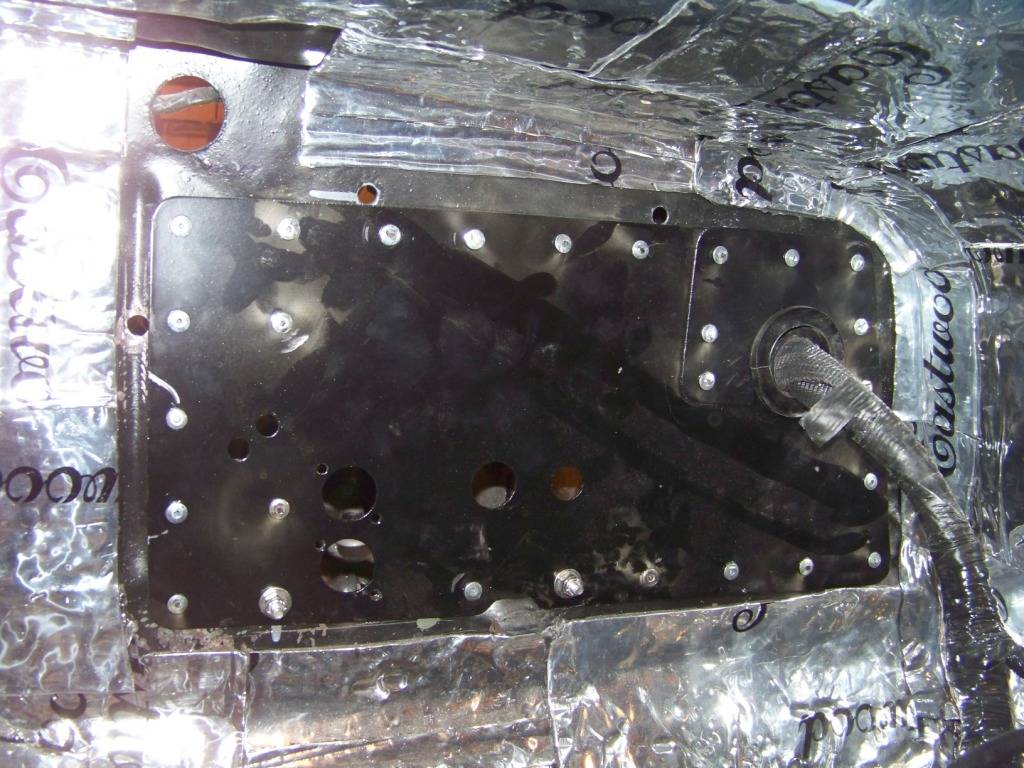
Passenger Side Bundle and HVAC bulkhead connections
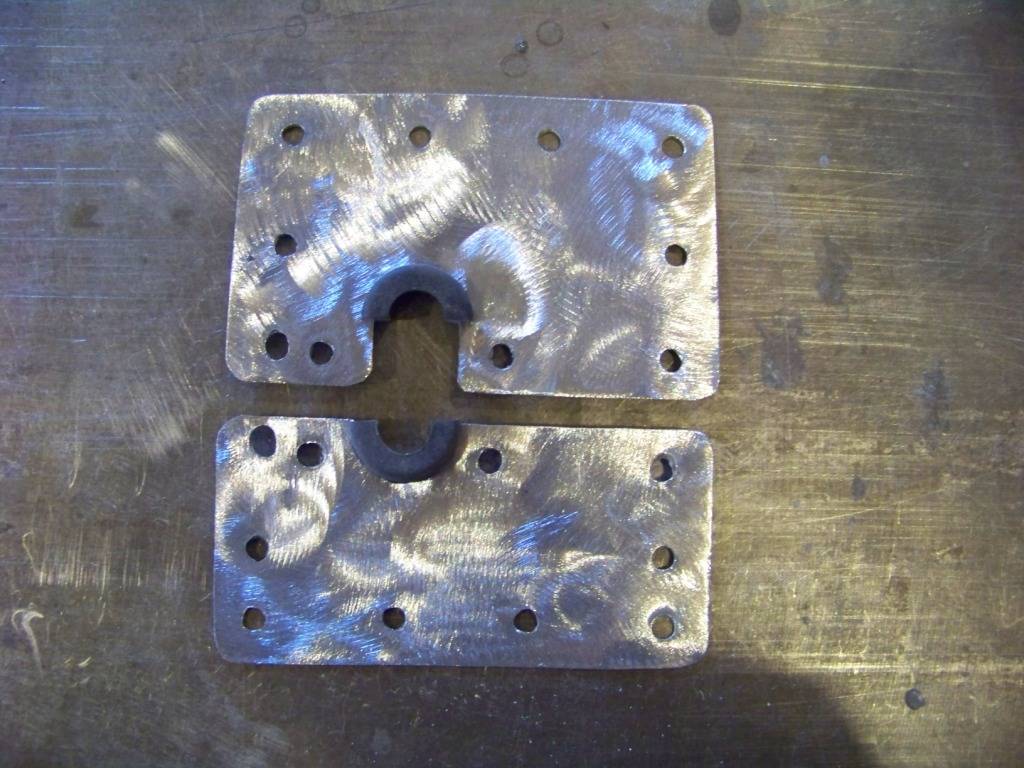
On the passenger side I had a similar situation with the larger bundle on that side, plus I needed to provide for the AC and heater connections. I also had the large rectangular hole in the firewall from where the heater core used to be to cover. I took care of all of these issues with a another two-piece cover plate that also had holes for the AC and heater bulkhead connectors. The picture below shows the two parts of the plate and the grommet I cut in half. The grommet is from McMaster, part number 6359K35. Lowes did not have a grommet this large.
In the above picture the two small holes in the left side of the plate are for vacuum lines between the HVAC unit in the interior and engine and heater valve under the hood. The vacuum lines will be routed through these holes with rubber grommets. The two larger holes positioned vertically are for the heater bulkhead fittings and the remaining two holes to the right are for the AC bulkhead fittings.
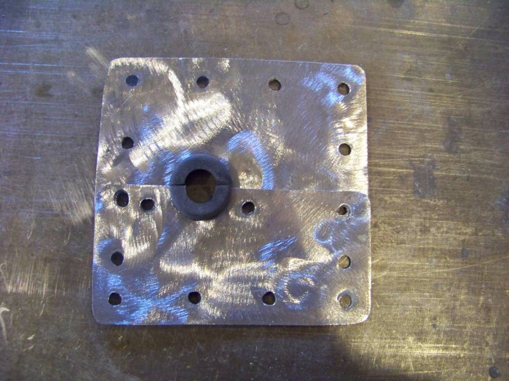
The next picture shows the plate installed around the passenger side wire bundle. The plate was installed with 3/16" steel rivets. The following picture shows a close up of the wire bundle area. Again, the plates overlap to sandwich and hold the two halves of the grommet in place around the bundle.
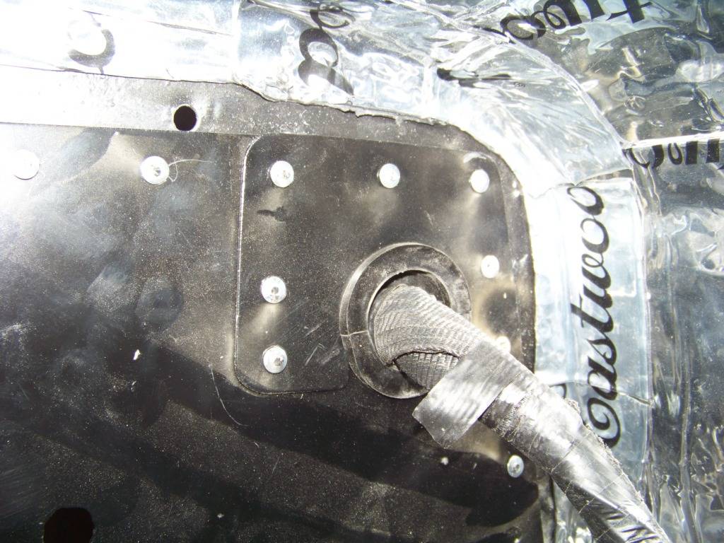
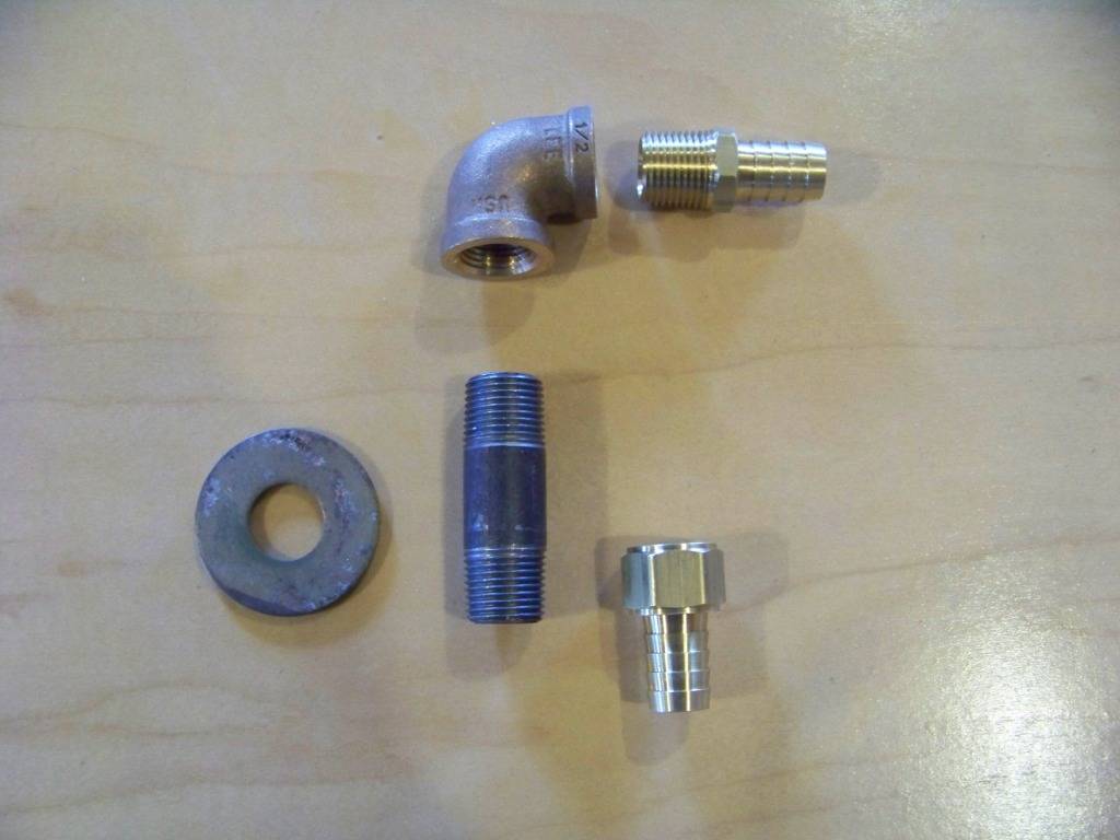
The HVAC unit from the GTO will sit about 4 inches behind the Lemans' firewall. So I needed some short heater hose connections in the interior side between the HVAC unit and the firewall cover plate. Since there were going to be hose connections on both sides I needed heater bulkhead fittings that had barbed ends on each side. I searched extensively online but could not find anything like that, so I made my own. The picture below shows the parts I used. Each fitting is made from a 1/2 inch pipe nipple, large washer to fit around the pipe nipple, a 1/2 inch pipe elbow and two barb fittings as shown. The pipe parts and washer are from Lowes, the barb fittings came from McMaster. They are part numbers 5346K59 and 5346K66. The washer was welded to the pipe nipple and had two holes to facilitate bolting the fitting the the firewall.
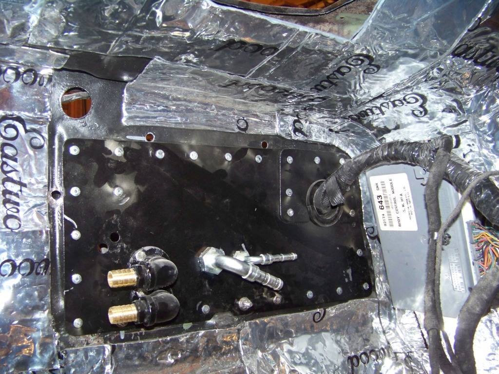
The following picture shows the heater and AC bulkhead fittings installed onto the plate.
I did my usual research into AC hoses and fittings and found that there is quite a few ways to go. I stumbled upon the EZ-Clip fittings from Aeroquip and liked them because they are easy for a home builder to make and install. The only special tool required is a pliers. Aeroquip sells the pliers for about $50, but amazingly I found the pliers along with many of the fittings I needed on Ebay for $5 each. I will talk about the AC hoses in a future post but I will give the part numbers for these bulkhead fittings here: FJ3514-0606S and FJ3514-1010S.
When I tried to install the interior heater hose connections I found that I placed the holes in the bulkhead too low, even after what I thought was good measuring and pondering. The fittings were moved up one hole, with another hole being drilled into the plate and the lower hole covered up. They were also rotated about 30 degrees up from vertical. In a future post I will try to show this connection, but it's tough to take pictures under the dash.
02-02-2013 #18 Registered User
- Join Date
- Apr 2010
- Location
- Sunny Flordida
- Posts
- 345
Wow! You are really making it happen. I admire your tackling so many tedious fabrication projects. Great job so far and I am looking forward to seeing the finished product. Keep at it brother!

[/URL]
02-04-2013 #19
Registered User
- Join Date
- Nov 2011
- Location
- Springfield, OH
- Posts
- 58
2004 GTO Interior Steering
This post will show installing the steering column from the GTO donor into the Lemans. I wanted to get the steering column installation figured out before the dash in went because the area is easier to get access to.
I had previously mocked up where I wanted to dash to go, so I knew about how far rearward the column needed to be to mate up with the relocated dash supporting structure.
I have seen different ways to do this on other builds but either I didnt care for what was done in the past or it wouldnt work in my situation. I didnt want to modify steering parts with welding and cutting on the column and linkage parts. I wanted a bolt together solution that was safe and secure.
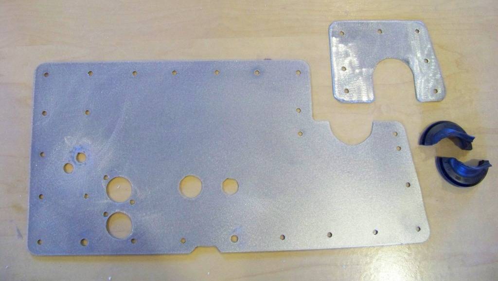
The main issue of this installation is supporting the column at the Lemans firewall. I first thought about using the column mount on the GTO firewall that was installed to support the dash, but it didnt seem secure enough, and I still had the issue with sealing the opening through the Lemans firewall where the steering shaft passes through. So I made an adapter that mounts the GTO donor column to the Lemans firewall. Its basically two plates connected by a sheet metal tunnel that the steering shaft passes through. One plate attaches to the Lemans firewall, the other bolts to the bottom of the GTO column. The description and pictures below describe the process.
The picture below shows the steering column closeout plate for the firewall of the Lemans. I removed the column clamp brackets as shown.
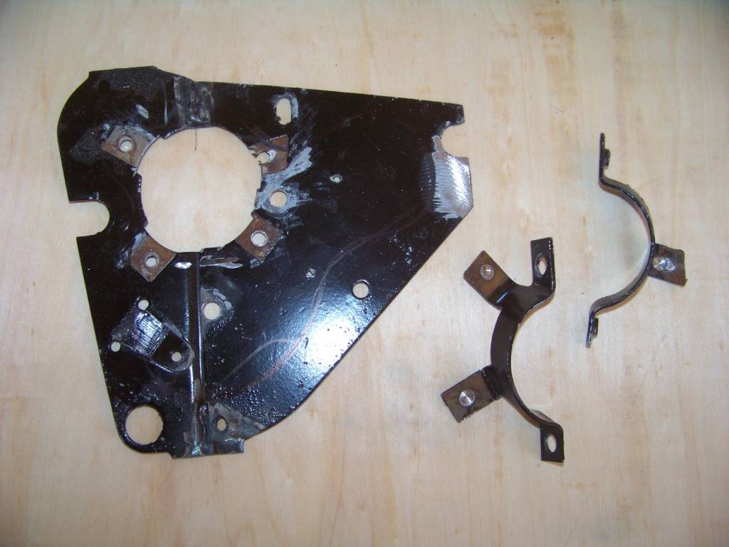
The picture below shows the bottom on the GTO column where it attaches to the GTO firewall:
The next couple of pictures show the plate I made to support the bottom of the GTO column:
The pictures below show the construction of the whole column adapter assembly.
The next two pictures how the steering column adapter assembly installed with the GTO steering column bolted to it.
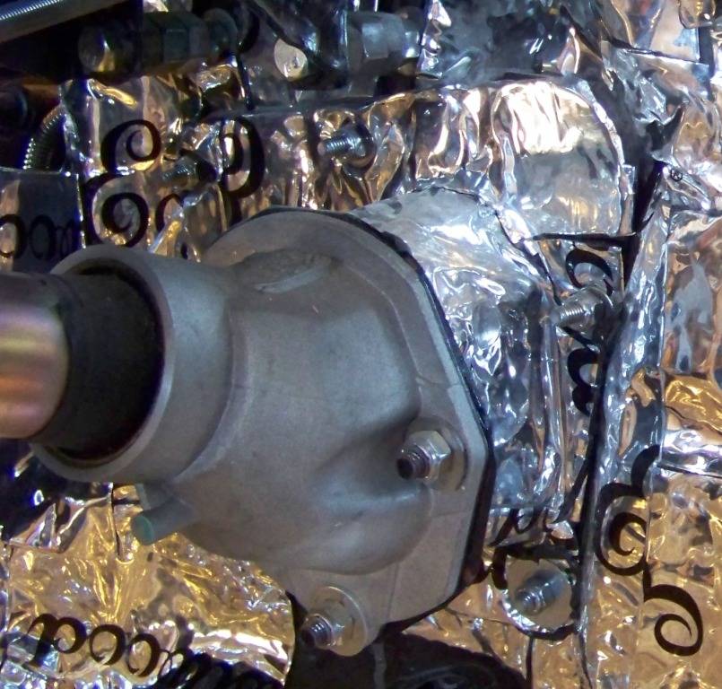
Now that the column is mounted, I could connect the GTO's steering column shaft to the steering gearbox. The bottom of the GTO donor column connected to the GTO steering rack with a ¾ DD connection. The shaft on the Jeep Cherokee steering gearbox is ¾ diameter, 30 spline with a flat. I bought the following parts to connect the two together:
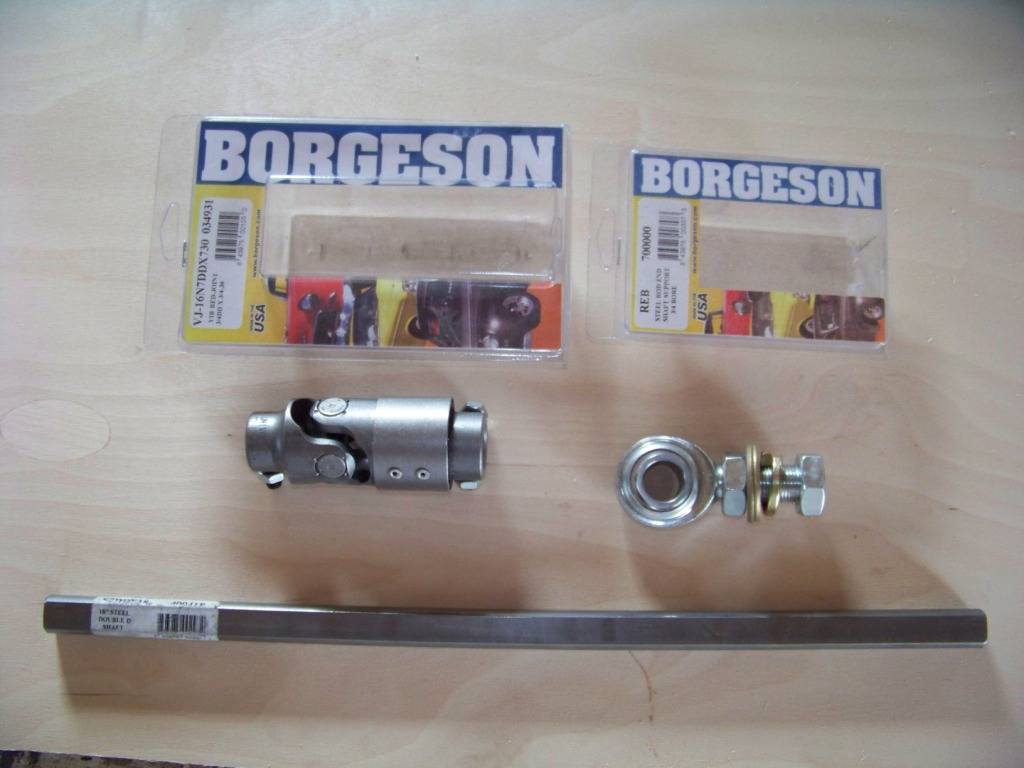
Parts are all from Borgensen; BRG-034931 u-joint, BRG-409418 Steering Shaft, and BRG-700000 3/4" support bearing.
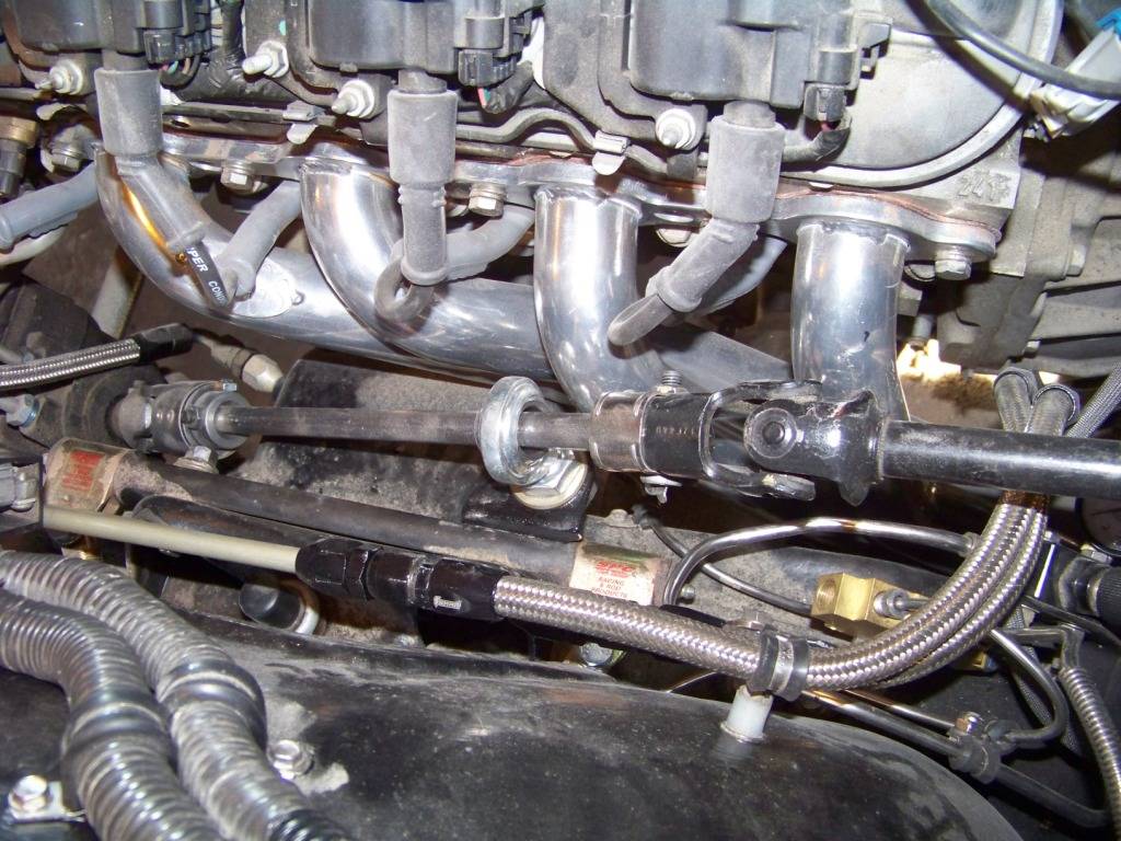
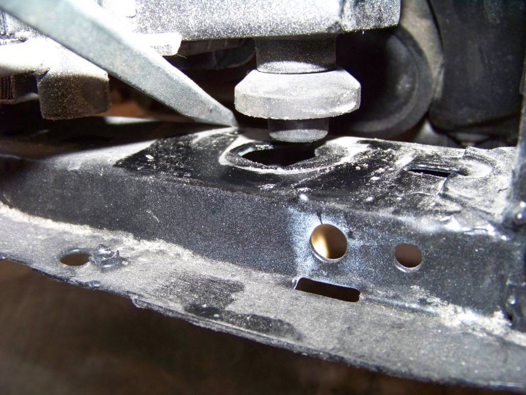
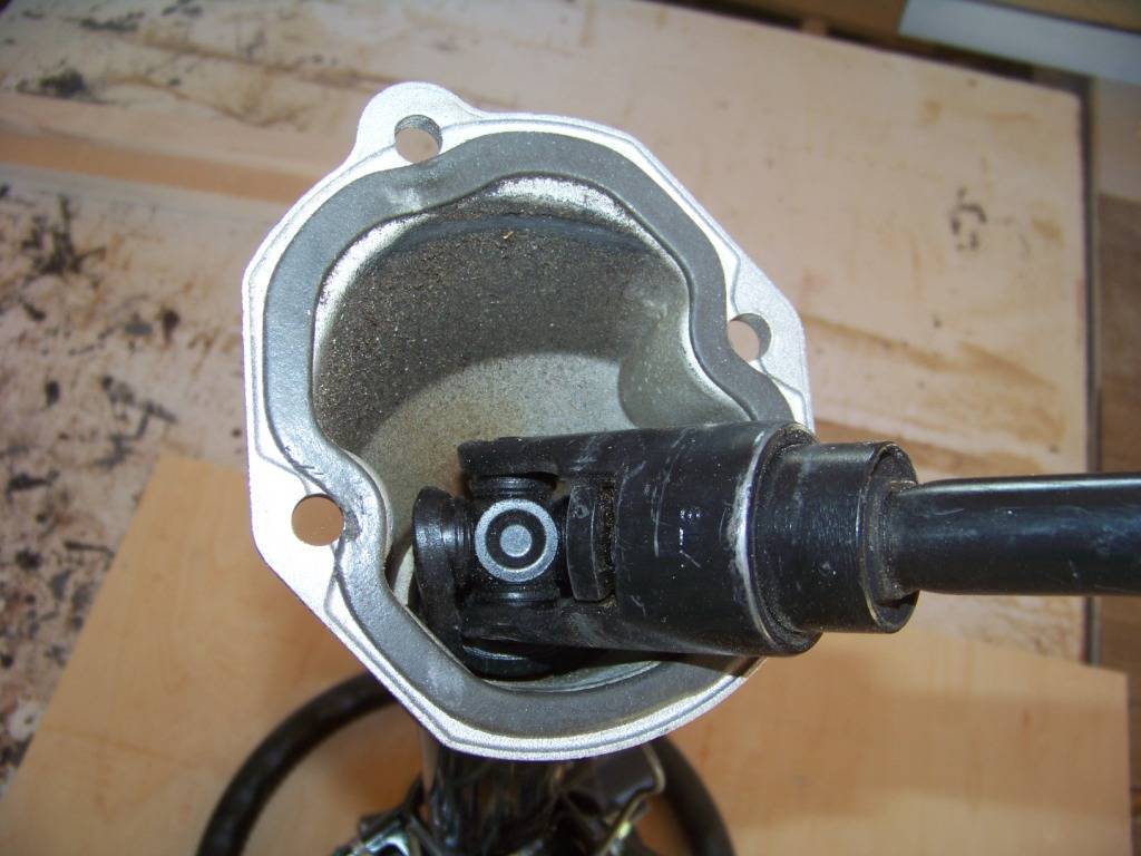
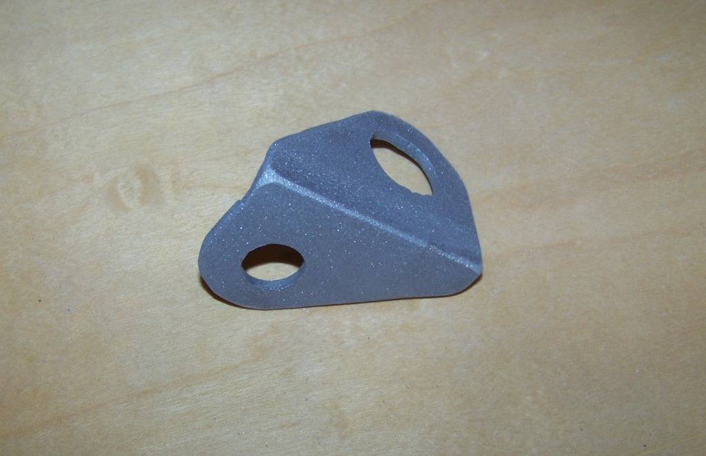
The coupler installed onto the steering gearbox and allowed for a connection to the ¾ DD shaft which was trimmed to length. This then connected to the ¾ DD opening at the bottom of the GTO column (in black in the picture below). Not shown here but there is another universal joint higher up in the GTO column. Since this steering connection has a total of three universal joints, an intermediate shaft support is required as shown below the middle connection. This shaft support is then supported by bracket I fabricated and installed on the rear upper control arm bolt. The bracket is shown below.
All the above parts installed as shown below.
Please feel free to ask any questions if any of this is unclear.
02-04-2013 #20 Registered User
- Join Date
- Apr 2004
- Location
- Cedar Rapids, IA
- Posts
- 999
Holy cow awsome stuff.
Maybe I missed it but what did you use for the fuel system?
Are you going to keep the cruise control?
With the GTO steering in place any thoughts on how you will make things like the blinker and hazzards work?
What else is on the GTO steering wheel?Some times I'm fast sometimes I'm half-fast

 Reply With Quote


