

Results 21 to 40 of 53
Thread: Battery and cable layout
-
09-16-2011 #21

 Registered User
- Join Date
- Aug 2008
- Location
- Pgh, PA
- Posts
- 2,177
Joe, I think you're right but even in a more general way. Audio stuff I've seen has been pretty much not up to the quality I'd want. For both battery and welding cable, I've seen both good and bad quality from both. The more expensive stuff I've used has generally had better strands inside, and tougher coating on the outside. Originally Posted by BulldawgMusclecars

 '66 GTO Vert Project "Red Ink", 462ci of stroked pontiac power, TKO600, SC&C Stg II+, Tubular lowers, Currectrac Rear suspension, Moser 12bolt w/Truetrack, Wilwood Master and discs all around, too much fun for words...
-
09-17-2011 #22 Registered User
- Join Date
- Aug 2004
- Location
- OK
- Posts
- 767
I am working on the same thing as most of you. I am trying to figure out where to route the cables. Some run them under the car some through the inside and down the ps channel. If so, what grommets did you use?
If anyone has pictures that would be great!
09-17-2011 #23 Registered User
- Join Date
- May 2011
- Location
- central Pa, USA
- Posts
- 189

I would also recommend good fine strand welding wire.
Tom
trailers are for boats and broke stuff.
09-17-2011 #24 Registered User
- Join Date
- Jul 2010
- Location
- Sacramento, CA
- Posts
- 1,214
^This! Originally Posted by 12sec ss
We have 37 grounds in police cars for all the equipment to properly work!-James
1974 Z28 SCCA C Prepared
1990 Firebird NASA CMC
2005 Mustang GT SCCA F-Street (new for 2015)
1989 Civic Si SCCA STC
09-19-2011 #25
Registered User
- Join Date
- Aug 2008
- Location
- Pgh, PA
- Posts
- 2,177
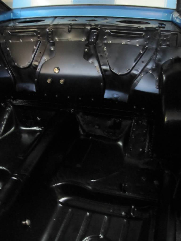
I used quite a bit of insulation in my project. Damplifier Pro as the first layer throughout the entire interior (floor, firewall) with Luxury Liner Pro on top of that. It allowed me to cut channels to route the wires through, as the Luxury Liner Pro is quite thick. Here's a pic of what it looked like prior to carpet. Originally Posted by Andrew McBride
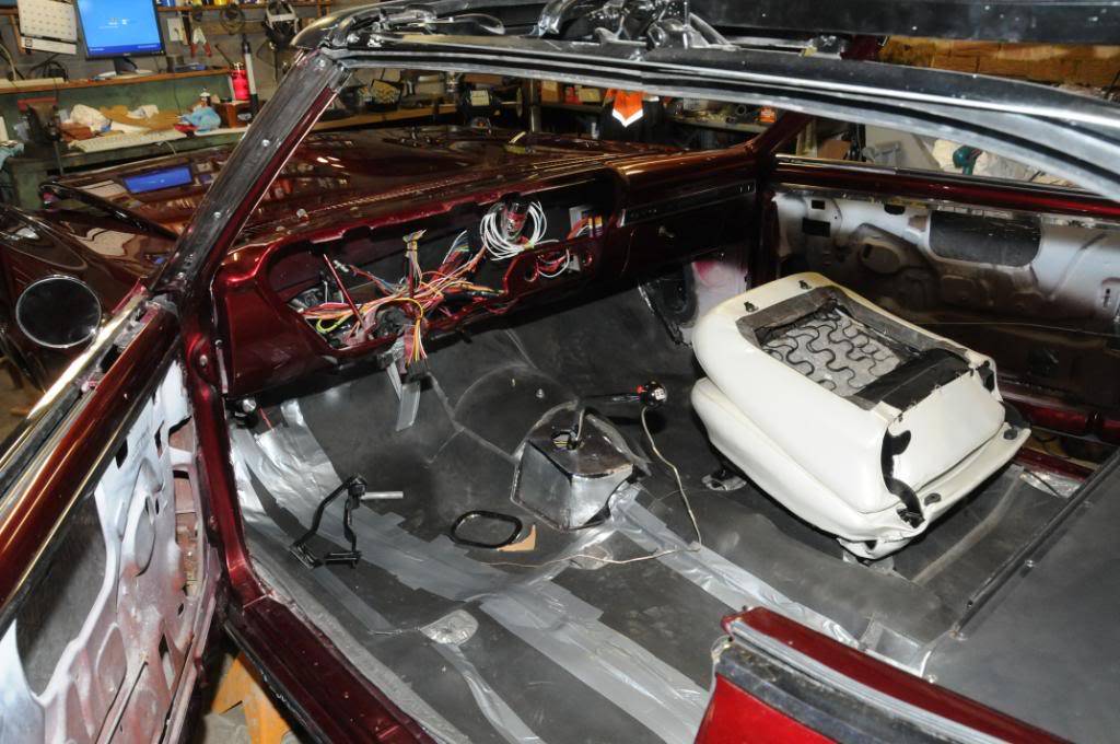
Under the duct tape there are seams/channels where some wiring was run. I'm not a big fan of running all the wiring under the car. Tried to minimize potential damage especially to the heavy gauge power cable.
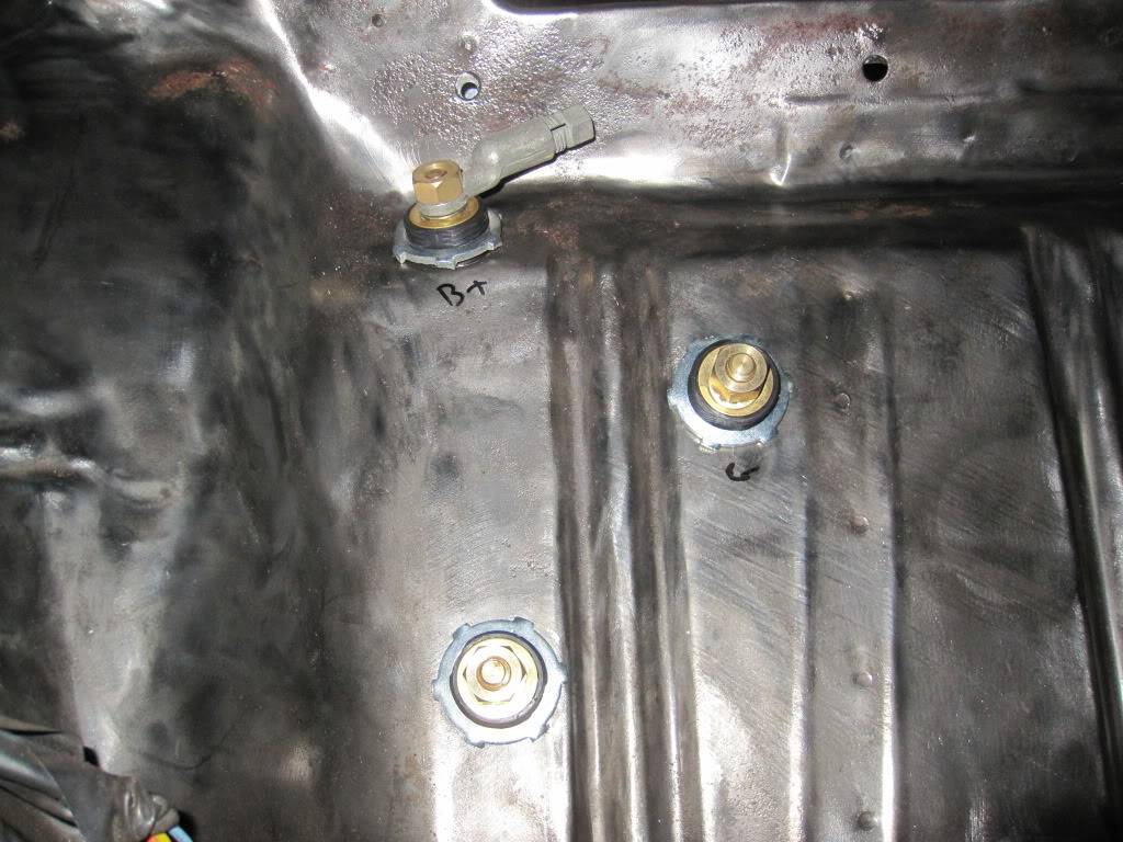
I used two kinds of grommets. One for the heavy power cable which transitions to under the car in the shifter area to go to the starter. For that I used a standard rubber type of grommet. The remainder all go through Earls of this type:
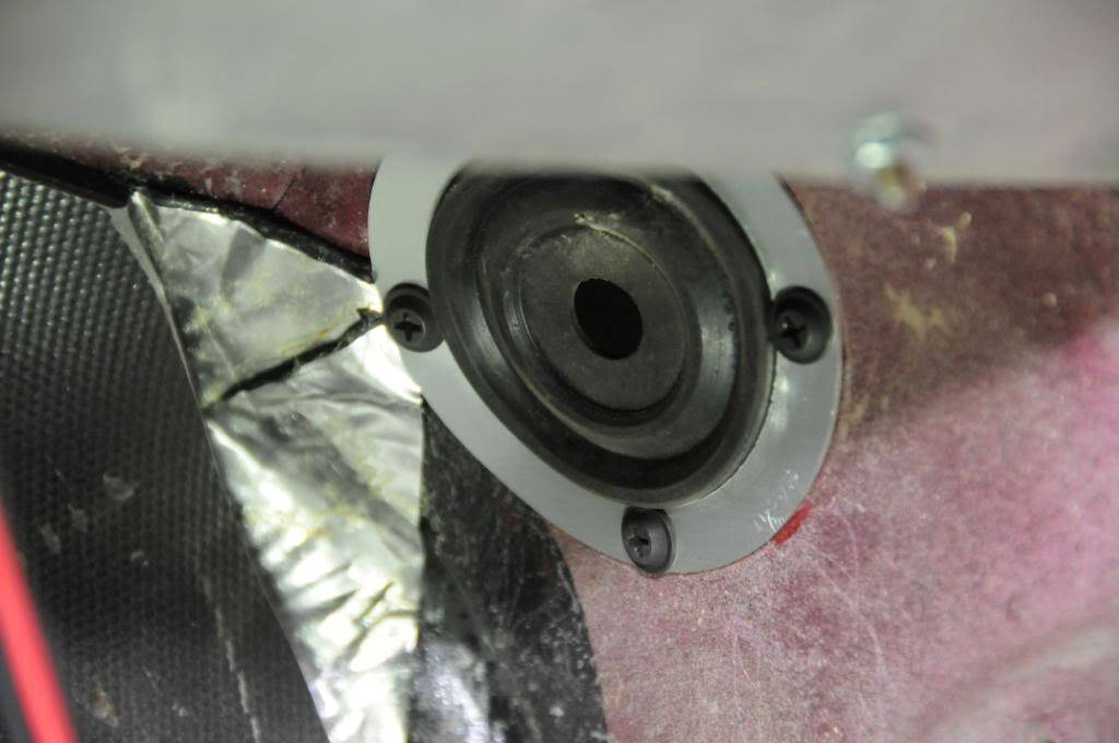 '66 GTO Vert Project "Red Ink", 462ci of stroked pontiac power, TKO600, SC&C Stg II+, Tubular lowers, Currectrac Rear suspension, Moser 12bolt w/Truetrack, Wilwood Master and discs all around, too much fun for words...
09-19-2011 #26 Registered User
- Join Date
- Nov 2006
- Location
- Ma.
- Posts
- 5,567
Has anyone used these panel pass throughs on the flat area at the top of the toe board where it meets the firewall with a Vintage Air Gen 4 A/C unit. It takes a big hole and I don't want to put them there if it interferes with the VA system.
Wayne
Car FINALLY home !!!!!! lol
Project FNQUIK https://www.pro-touring.com/showthre...ghlight=FNQUIK
09-20-2011 #27 Registered User
- Join Date
- Dec 2007
- Location
- Carlsbad, Ca
- Posts
- 1,213
i saw it asked but didnt read an answer. can you use the alternator charging line as the power feed the the junction blocks?
Tim
The WidowMaker: Garage Built 70 Chevelle
Special Thanks To: Rushforth Wheels, MuscleRodz, Kore3 & SC&C
Build Thread Link
09-24-2011 #28 Registered User
- Join Date
- Oct 2006
- Location
- Morristown, NJ
- Posts
- 154
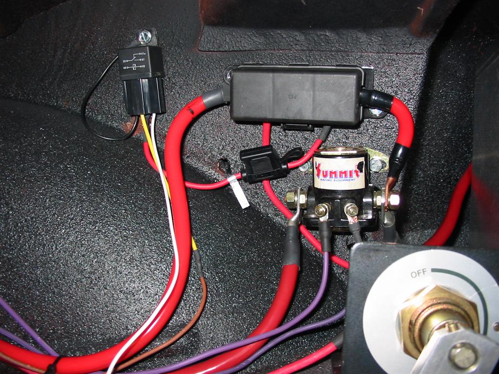
I went with this layout.
-The battery, maxi-fuse, Ford Starter Solenoid, and Disconnect Switch are in the trunk.
-The alternator is protected on both sides with a fuse or a circuit breaker.1973 Camaro Type LT/RS
http://www.apiem.com/camaro
09-24-2011 #29
Registered User
- Join Date
- Oct 2006
- Location
- Morristown, NJ
- Posts
- 154
Here is picture of the trunk.
 1973 Camaro Type LT/RS
http://www.apiem.com/camaro
01-14-2012 #30 Registered User
- Join Date
- Apr 2005
- Location
- IN/MI border
- Posts
- 1,904
Well I never persued this area but am about to again. Looks like several different options to choose from, not familiar at all with what size fuses to use and such. Still not sure how to route and setup this thing. I thought the shut off switch would be in line to shut everything down, but by the schematic above it only shuts off the fuse box??
I have the ford style solenoid. I'll get some 1/0 wire.
01-16-2012 #31 Registered User
- Join Date
- Jul 2007
- Location
- Los Angeles, CA
- Posts
- 1,303
Instead of using grommets I used bulkhead connectors and routed the cables along the trans-tunnel inside the car to the passenger side floor:
To the rear there was a firewall I made that sat between the trunk and interior pass compartment again used bulkhead connectors:
02-09-2012 #32
Registered User
- Join Date
- Apr 2005
- Location
- IN/MI border
- Posts
- 1,904
Well I messed with it a little... I put in a 1 awg to the trunk. So from the Alt to the starter solenoid is a 4 awg?

02-14-2012 #33
Registered User
- Join Date
- Aug 2007
- Location
- NJ/PA
- Posts
- 396
Hey Buddy,
Ive been following this thread very close. Do you have a final drawing of how you ran it like your first post..? That was the clearest to me and Im sure would help many others. Also maybe put some links of part numers of what you used. Im gearing up to buy soon and like the look and safty of your system. Simple yet effective.
Is this the shutoff and ford style solenoid you used?
http://www.jegs.com/i/JEGS-Performan...10305/10002/-1
http://www.jegs.com/i/JEGS-Performan...10308/10002/-1
If youd rather talk via phone/email lmk. Thanks, Steven
Revised:
Did some serching and reading..not sure if you are going carbed or efi on your set up but read the warning on jegs site for the ford style starter solenoid:
WARNING! This solenoid DOES NOT use suppression diodes. Use of this solenoid on vehicles with Engine Control Computers will result in permanent damage to the computer/processor.
as seen here...
http://www.jegs.com/i/JEGS-Performan...10308/10002/-1
Im not a wiring guy and am not sure what this means. Being that I am going efi and will have a computer can someone explain this in layman's terms.
02-15-2012 #34
Registered User
- Join Date
- Apr 2005
- Location
- IN/MI border
- Posts
- 1,904
Huh, yeah that doesnt make sense. Especially since the solenoid is only in the main starter cable. This is why I hate wiring so much.
02-16-2012 #35
Registered User
- Join Date
- Aug 2007
- Location
- NJ/PA
- Posts
- 396
Are those the products that you bought for your car? Im not trying to fry my 400+ computer due to a 20 dollars solenoid.. I hate wiring the same, but need it done right even if it kills me learning it. Originally Posted by BuddyP
02-16-2012 #36
Registered User
- Join Date
- Apr 2005
- Location
- IN/MI border
- Posts
- 1,904
I didn't buy those exact parts but they are identical. I forget the manufacturer of the solenoid but the shut off switch is a Taylor (looks identical to the one you posted).
Here's a diagram of my wireing to date. I have 4 awg ground straps (2) between body and subframe and will put 1 between motor/body and 1 between motor/subframe. If any body wants to help me add to this diagram I'd greatly appreciate it!
Last edited by BuddyP; 02-16-2012 at 12:19 PM.
02-16-2012 #37 Registered User
- Join Date
- Jan 2010
- Location
- South Carolina
- Posts
- 115
Buddy, relax & think about it slow.
you have three circuits basically:
-the starter lead (solenoid protected at back)
-the battery charging lead (from alternator, only needs smaller AWG since it is only trickle charging the battery)
-shut off switch (keeps B+ from being applied to the vehicle when you want to do maintenance, so you don't wear out battery clamps.
you need to take Amargari's picture, print it out, and take his alternator lead off the maxi fuse, and onto the "ON" side of the cut out/shut off switch,
and then, i think you will understand it better.
think of water flowing around the wires:
-big power to crank
-small flow to charge
-no flow to do maintenance.
02-16-2012 #38
Registered User
- Join Date
- Apr 2005
- Location
- IN/MI border
- Posts
- 1,904
I think I have the main cable figured out but unsure what to tie in between IGN, fuel pump and such and what should have a fuse and how big and such.
02-17-2012 #39 Registered User
- Join Date
- Sep 2006
- Location
- Pacific Wonderland
- Posts
- 67
Hey BuddyP if you want to PM me I can help you with your questions. I had back surgery 3 weeks ago and I'm just laying around the house now.
If it breaks I didn't want it in the first place.
69 GTO
72 FIREBIRD
64 BONNEVILLE FUNERAL COACH
70 JAVELIN
52 F1 FORD PU
29 FORD PU
85 ALFA ROMEO
ASSORTED DUCATI'S
91 BLAZER LOWRIDER
02-17-2012 #40
Registered User
- Join Date
- Sep 2006
- Location
- Pacific Wonderland
- Posts
- 67
Revised:
Did some serching and reading..not sure if you are going carbed or efi on your set up but read the warning on jegs site for the ford style starter solenoid:
WARNING! This solenoid DOES NOT use suppression diodes. Use of this solenoid on vehicles with Engine Control Computers will result in permanent damage to the computer/processor.
as seen here...
http://www.jegs.com/i/JEGS-Performan...10308/10002/-1
Im not a wiring guy and am not sure what this means. Being that I am going efi and will have a computer can someone explain this in layman's terms.[/QUOTE]
The layman's definition is: A solenoid is made up of a coil of wire and an armature. The armature is a piece of iron that moves as a result of the magnetic field the coil makes when energized. The movement of the armature operates the switch part of the solenoid. Its just a big relay. The problem comes when the solenoid is de-energized and the movement of the armature past the coil can produce a voltage spike which is seen in all the connected wiring and if the spike is large enough it can affect adjacent wires. The spike that is created will be AC voltage and most automotive electronics have no protection from AC voltage and as result are damaged. The suppression diodes are designed to control this voltage.If it breaks I didn't want it in the first place.
69 GTO
72 FIREBIRD
64 BONNEVILLE FUNERAL COACH
70 JAVELIN
52 F1 FORD PU
29 FORD PU
85 ALFA ROMEO
ASSORTED DUCATI'S
91 BLAZER LOWRIDER

 Reply With Quote


