

Results 61 to 80 of 155
Thread: 69 Camaro LS2/4L70E install
-
03-30-2012 #61

 Registered User
- Join Date
- Nov 2005
- Location
- Houston,TX
- Posts
- 1,162

What did it take to get the replacement header from Stainless works? I called them about this issue and asked about an "upgraded" header a week or two ago and they claimed to know nothing about it or any interference issues? Do you have a contact over there you dealt with directly? I still have mine new in the box awaitng install so now would be the time to get a replacement if possible....
71' Nova - LY6, T56
-
03-31-2012 #62 Registered User
- Join Date
- Sep 2004
- Location
- Metamora, Illinois
- Posts
- 1,614
I bought my headers through Frank at Prodigy Customs. I worked with Frank to get the process started and then directly with Jason at Stainless Works. Let them know the headers are new in the box. Originally Posted by NvrDun71

03-31-2012 #63 Registered User
- Join Date
- Jul 2009
- Location
- ma.
- Posts
- 386
Looks great,your doing what I plan on doing to my 69 Im starting with a restored car with suspension mods done too. It looks like its going to be harder this way not to damage anything but it also looks like you can sit back and look at it without the stress of needing everything else.
Ill be using your project on what parts I need and how to do it...great to know what to or not to do before I start.
cant wait to see it finished and tell us the difference of what its like to drive with the new drivetrain.
04-13-2012 #64
Registered User
- Join Date
- Sep 2004
- Location
- Metamora, Illinois
- Posts
- 1,614
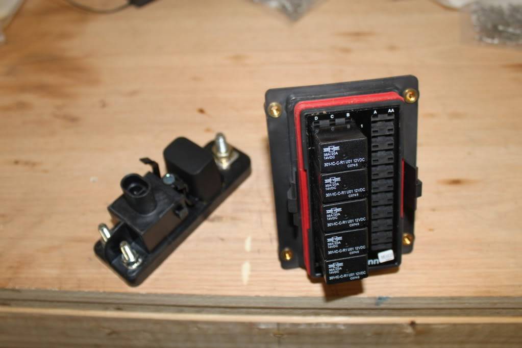
The UPS truck dropped off a package from Waytek. Now I have all the items and tools to create my fusepanel. I will be using a Cooper Bussman RTMR Panel 15303-6-2-4. This panel allows you to us up to 5 micro relays, ISO 280 footprint, and 10 mini-blade fuses. I also ordered a power relay module, an assortment of metri-pack 150 & 280 connectors, terminals & cable seals with the appropriate delphi crimpers. This should keep me busy for a bit/
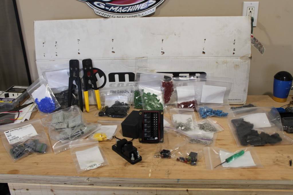
The fusepanel is extremely compact and measures 4.25" x 3.4"
04-14-2012 #65
Registered User
- Join Date
- Sep 2004
- Location
- Metamora, Illinois
- Posts
- 1,614
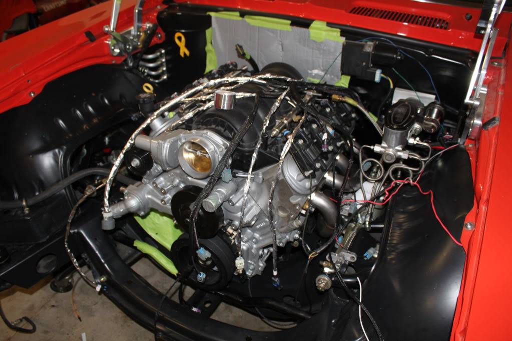
Making more progress. I test fit my harness and after making some minor adjustment the to the harness routing I wrap any part of the harness that is touching or close to a heat source with DEI Cool tape. I bought a 30ft x 1 3/8" wide roll for $30 and have a decent amount left over. It's pretty easy to work with, but at $1 per foot use it wisely. Now I just need to connect everything and secure the harness....then on to the next item on the list.
On another note, I got my harness from SSP wiring and opted for the show car harness wrap. It is black mesh sheathing that encapsulates the entire harness. It looks great, but In hindsight I wish I would have not gotten this. It snags on everything when you install it and you can not access the wire harness if needed. Hopefully I won't have any issues..
04-15-2012 #66
Registered User
- Join Date
- Sep 2004
- Location
- Metamora, Illinois
- Posts
- 1,614
Got a ton of stuff done yesterday and things are moving along nicely!. The plan for today is:
- Loosely install the radiator support and makes mounts for the ecm, tcm & fuse panel. Then the wiring can begin.
- Measure driveshaft length. Will look into getting the stock unit shortened, or a I may just bite the bullet and order a new one.
- Tap water pump heater hose inlet/outlet for AN to NPT adapters
- Install front carpet
- Continue working on an idea for low mount a/c that doesn't require notching the sub frame.
- Order more parts: stover nuts, wire, ls3 coolant crossover tube, etc
04-15-2012 #67 Registered User
- Join Date
- Jul 2011
- Location
- Atlanta, Ga
- Posts
- 30
Looking slick man!
1967 Mustang Coupe
2011 Mustang GT/CS
1971 C-10 SWB Shop Truck
1970 GMC Suburban (Betty) Tow Rig
05-18-2012 #68
Registered User
- Join Date
- Sep 2004
- Location
- Metamora, Illinois
- Posts
- 1,614
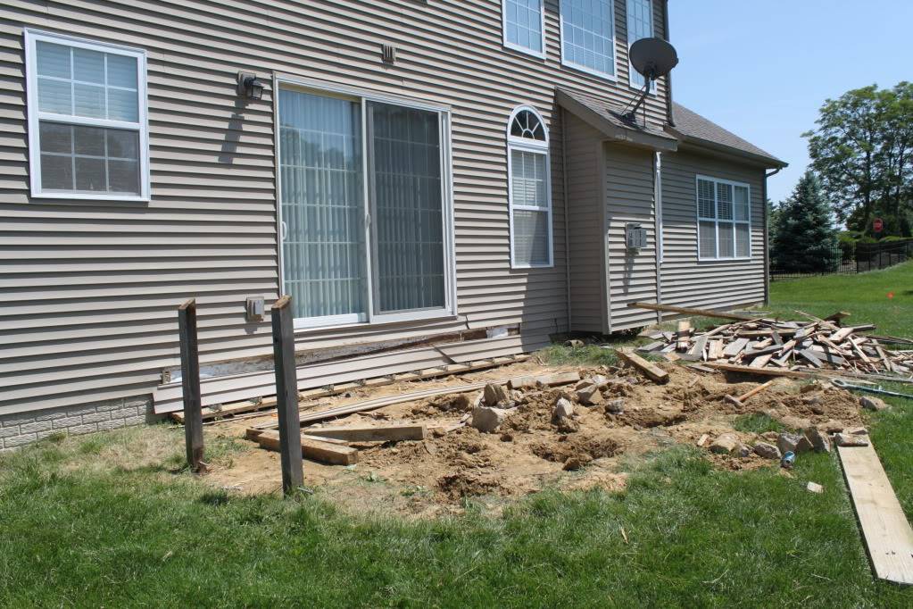
Been a little sidetracked as we are having some landscaping done, once I get the 12x16 deck removed. We are going to have a brick patio with a firepit installed. Well enough of this and onto the car pics.
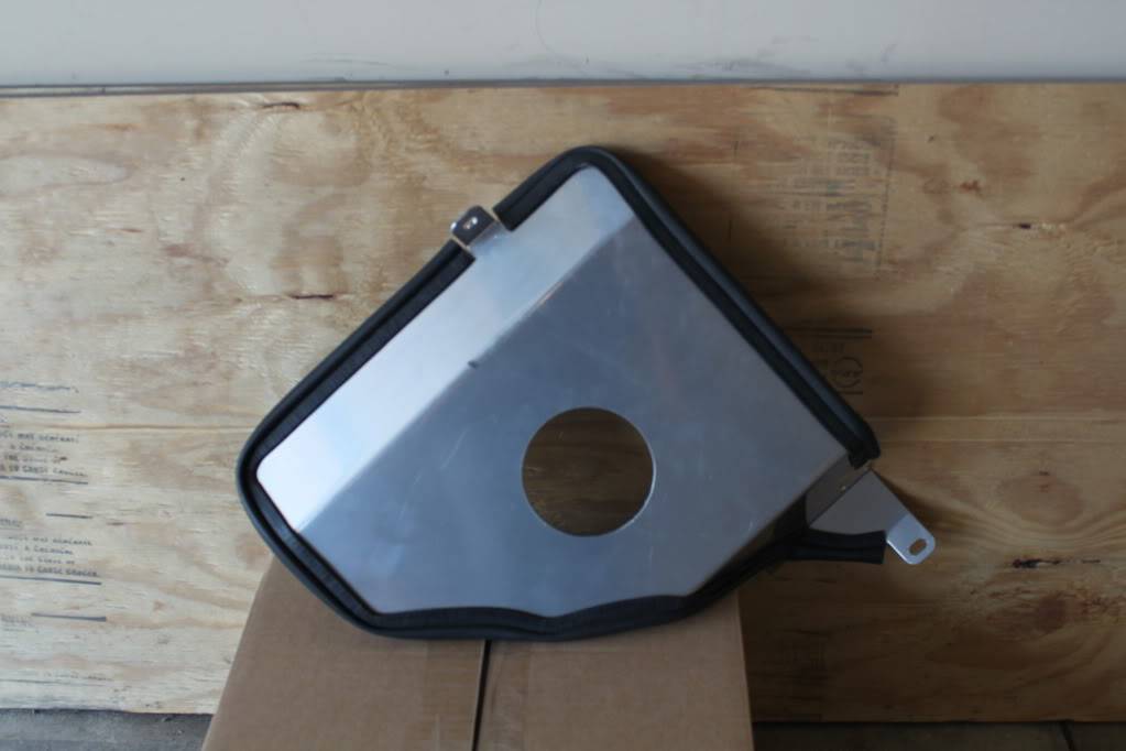
For starters I ordered a cold air intake kit. After looking at everything I decided to go with the Spectre Muscle Car LS Conversion Intake Kits, Spectre Muscle Car LS Conversion Intake Kits p/n 900239K . I was all excited then I opened the box and this is all I got. Yep, all they sent was the bracket and it was apparent the item had been previously installed??? There were no intake tubes, mounting hardware, filter, couplers, etc. Anyways the bracket doesn't fit my car as I have an over sized radiator so it's going. Its a shame because it seemed like it would have been a nice setup for the $$$. Looks like I may go with an Airaid U-Build it setup, but they are expensive. If anyone has any suggestions let me know.
05-20-2012 #69
Registered User
- Join Date
- Sep 2004
- Location
- Metamora, Illinois
- Posts
- 1,614
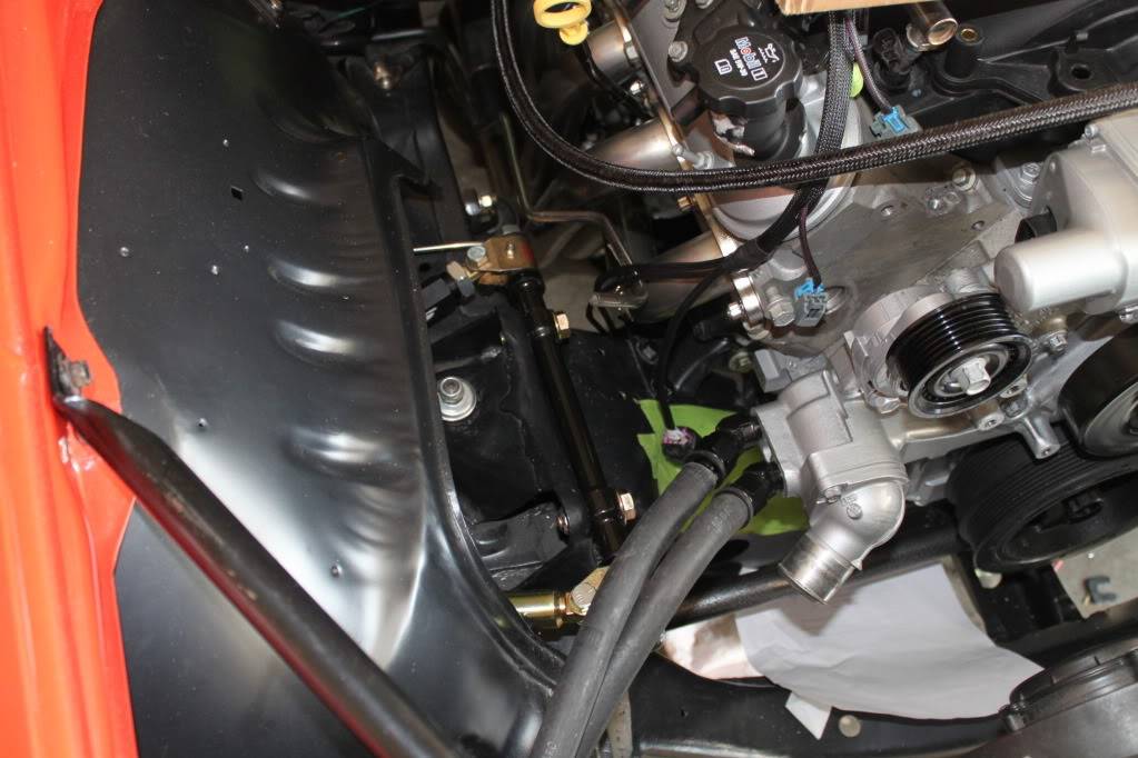
Converting heater hoses inlet/outlet to AN fittings
Due to clearance issues I converted the water pump heater hose inlet/outlet over to accept AN fittings. After removing the pressed on fitting I tapped each hole. The smaller one is a 3/8" NPT and the larger 1/2" NPT. The larger hole would have tapped a lot easier if I drilled it out to the proper size. Once the hoses were tapped I installed the appropriate size npt to -10an male fittings in the pump. On the heater hoses I am straight -10 socketless hose ends with Gate Power Grip clamps. Here is a pic without the Gates Power Grip clamps installed.
05-20-2012 #70
Registered User
- Join Date
- Sep 2004
- Location
- Metamora, Illinois
- Posts
- 1,614
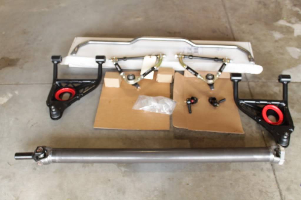
More parts to install. SC&C Stage 2 UCAs, SPC LCAs, Helwig swaybar and SPC ride height shim pack. I will re-use my Hotchkis coils springs and Bilstien shocks. I also ordered a new Strange 3" chromoly drive shaft with a billet yoke from Midwest Chassis.
05-20-2012 #71 Registered User
- Join Date
- Aug 2006
- Posts
- 82
Hey Rocketrod,
I have been following along with your build and I am pretty much on the same path that you are. I recently ordered the same Spectre system but my part number was 900234K which is for the filter on the drivers side. I had just missed the last kit they had when I ordered so it actually took me a month to wait on another kit. If you received that closeout panel with the rubber gasketing already attached then yes it probably had already been used. Those pieces came in different bags in mine. I worked on trying to get mine to fit last weekend. I have about three or four areas that are not working out and I was going to send pictures to Spectre to see what they say. I don't have my hood on the car right now but I am pretty sure that panel needs to be tweaked in order for the fender braces to fully pass through. At least that is what I found on mine. Plus I couldn't get the main pipe to line up with the through hole in the panel. It uses a rubber boot to make the bend but there was no way I could get it to work. In the end the kit can still work without using that heat shield panel if you use one of their braces. I will let you know what I find out when I send them some of the pictures of mine. Sorry about your kit. If I am able to get this to work I still think this is a good kit and probably priced lower than the other options out there.
KUSI
05-24-2012 #72
Registered User
- Join Date
- Sep 2004
- Location
- Metamora, Illinois
- Posts
- 1,614
Looking forward to hearing from you. I do think I am going to build my own cai buyinh the pieces from http://www.frozenboost.com/ Originally Posted by KUSI
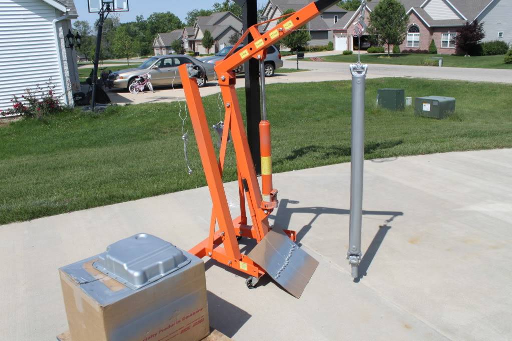
Not a lot getting done, but I did manage to spray the drive shaft, trans pan, low mount ac bracket and some other miscellaneous parts. Hopefully I will get a chance to work on the car this weekend.
05-26-2012 #73
Registered User
- Join Date
- Sep 2004
- Location
- Metamora, Illinois
- Posts
- 1,614
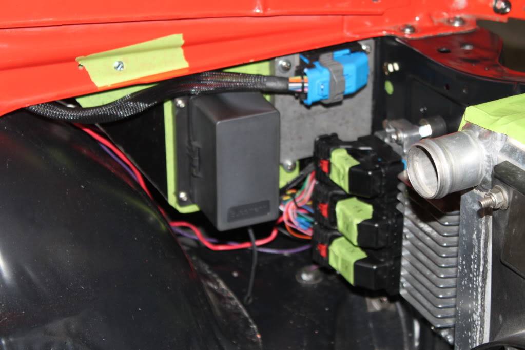
Messed around in the garage a little today. I made battery cable for starter, fuel line connecting tank to main line, installed oil pressure sending unit and painted the bracket I made to mount my fuse panel and tcm.
Pic of bracket with fuse panel and tcm installed. I made the bracket using 16 gauge metal. This will be mounted to the radiator support on the driver side of the engine bay.
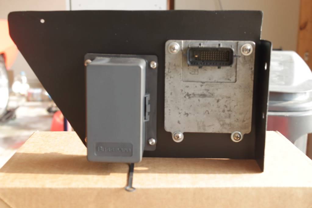
Mock up bracket installed and ecm mounted on radiator support. I'll posted better pics with more detail once they permanently mounted.
05-27-2012 #74
Registered User
- Join Date
- Sep 2004
- Location
- Metamora, Illinois
- Posts
- 1,614
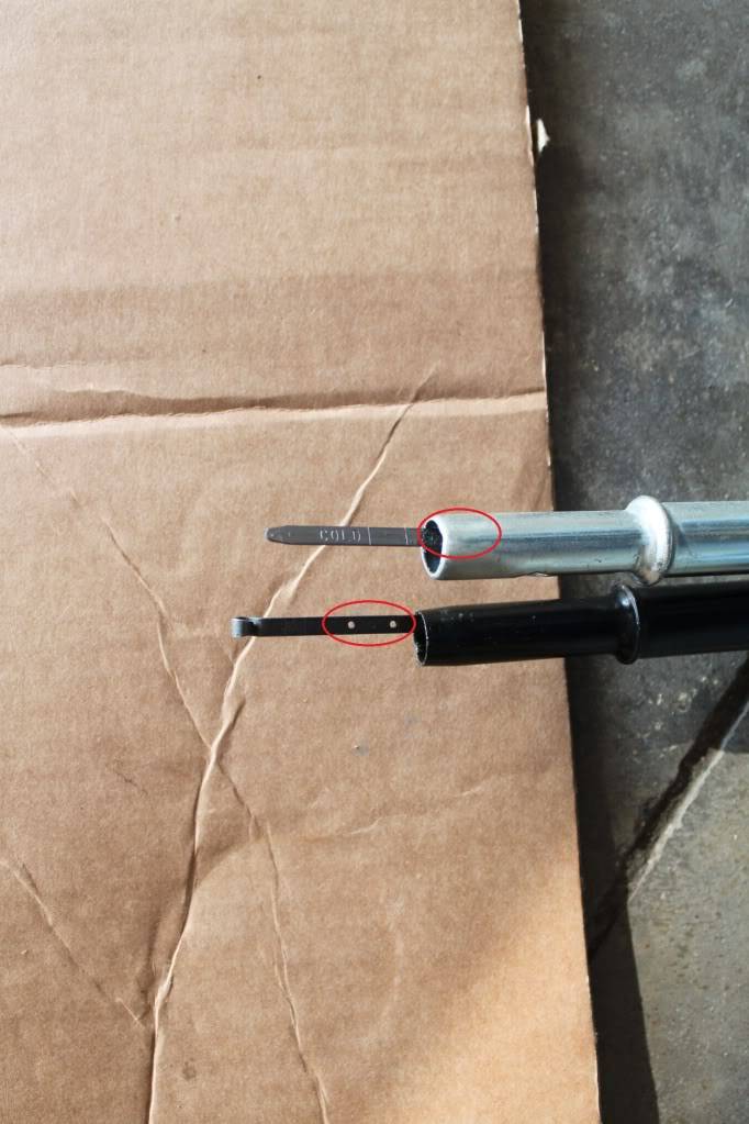
Getting ready to install the trans dipstick and tube. I am comparing the original TBSS tube/indicator to the new LS2 tube/indicator (GM # 92159815 out of 2006 Pontiac GTO) and noticed there is a big difference in how far the indicator protrudes into the pan. The black tube is out of the TBSS and the other is the new tube. The low/full indicator markings protrude a lot deeper into the pan than the new one (see pic below). Anyone have any thoughts on this?
I think I am just going to use the new indicator and cut down the TBSS tube until the low/full marks stick match the TBSS.
Not the best pic, the black tube is the TBSS, the other one is the new GM tube
05-27-2012 #75 Registered User
- Join Date
- Jul 2006
- Location
- Lake Tillery NC
- Posts
- 841
69 Camaro LS2/4L70E install
Cool Project! Love the detail work you are doing!
Michael Tucker
Project "Trouble" 1969 Camaro DSE subframe, quadrilink, 13" wilwood brakes, Rated X Rushforths, LS2/T56
1968 Camaro
05-27-2012 #76
Registered User
- Join Date
- Sep 2004
- Location
- Metamora, Illinois
- Posts
- 1,614
Thanks! I am starting to see light at the end of the tunnel! Hopefully I will be able to start the engine soon!
05-28-2012 #77
Registered User
- Join Date
- Sep 2004
- Location
- Metamora, Illinois
- Posts
- 1,614
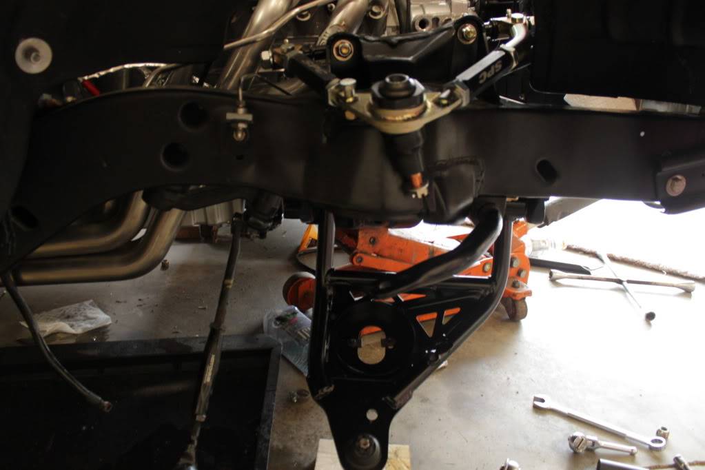
I finally got my SC&C Stage 2 UCAs, SPC LCAs, Helwig swaybar and SPC ride height shim pack installed. This setup allows you to adjust the ride height using a shim pack kit. I put in one shim so I will have to see how see sets once I get everything aligned and the car fully assembled.
[/QUOTE]
Not many pics, but replacing the upper/lower control arms are pretty straightforward. I did have one heck of a time getting the driver side coil spring to seat properly in the frame, but other than that not much to it other than time. I still need to align the front end, which I will be doing myself using the SPC Performance Pro Series FasTrax Adjustable Caster/Camber Kit SPC Align, http://www.summitracing.com/parts/SPS-91000/
06-03-2012 #78
Registered User
- Join Date
- Sep 2004
- Location
- Metamora, Illinois
- Posts
- 1,614
Well I gave up on buying a deep aftermarket trans pan. The PML will fit a 4l70e, but it is so deep it would hang down below my sub frame. Anyways I opted to install a B&M Drain plug kit, 80250. Originally Posted by Rocketrod
I spent the rest of the morning securing the radiator, installing the lower radiator hose, installing the an fittings in the water pump, bolting in the trans cross member and taking care of a zillion other things that need to be done. The list is getting shorter.
06-07-2012 #79
Registered User
- Join Date
- Sep 2004
- Location
- Metamora, Illinois
- Posts
- 1,614
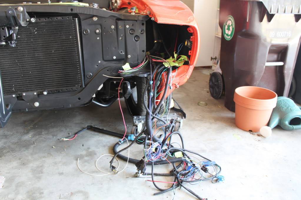
Well I have been putting this off for a while, but it is now time to finish the harness install. This will be split into two stages. Tthe first will be building a harness to run the required wires into the interior. This will include wires for speedo, tach, ODB II port, check engine light, fuel pump relay trigger, etc. The second stage will be building a custom fuse fuse panel for the all the relays (headlights and fans) and other engine circuits (maf, coilpacks, ecm, tcm, etc).
So here is what the rats nest I created previously....it should look much nicer and be easier to work on when I am done.
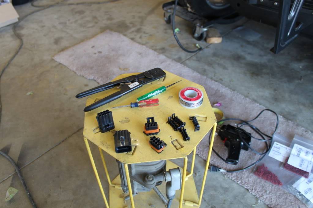
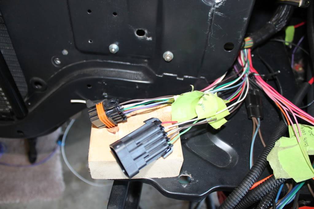
To connect the engine harness to the interior harness I will be using two 8 pin metri-pack 280 series connectors. In hindsight, I should have ordered 10 pin connectors, because I can't fit everything in one 8 pin connector.
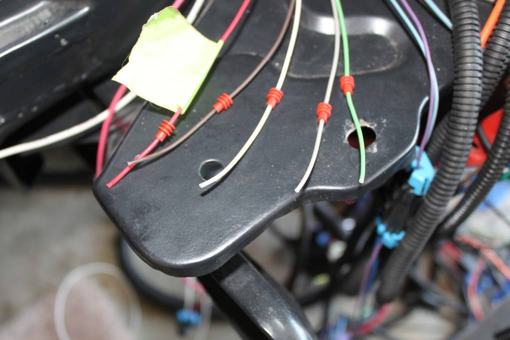
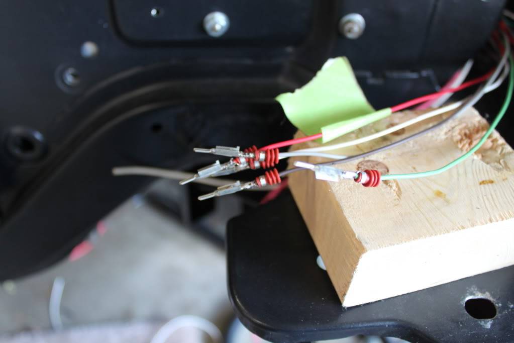
First step is to label wires, determine wire routing, cut wire to length and install the cable seals
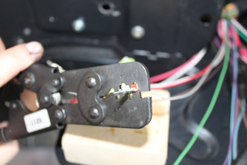
Crimping terminals ends and cable seals. The proper crimpers make this job a breeze.
Everything is crimped and soldered. Now I just need to insert the pins into the connector bodies.
Job completed! I installed a male and female connector to eliminate the chance of hooking up the wrong connectors. Of course this may not stop me from connecting them to each other, but nothing will work, which should reduce the troubleshooting time. The next step is to build a harness to run the wires into the interior....
06-07-2012 #80
Registered User
- Join Date
- May 2009
- Posts
- 24
Thats the motor a wish I had . One Day after mine pops. Looks GREAT
Tags for this Thread

 Reply With Quote


