

Results 1 to 20 of 51
-
04-26-2009 #1
 Registered User
- Join Date
- Dec 2004
- Posts
- 203
Torsional rigidity--measuring and increasing
I have a lot of mods to my '68 Camaro, but haven't done anything yet for stiffening up the chassis despite autocrossing regularly for over a year now and steadily improving my times. I just ordered DSE integral subframe connectors as well as Al solid body mounts and front struts from the firewall to subframe horns from Chris Alston. I intend to install these three elements and most likely also the tiger cage (working on the budget) and measure the increase, if any, in torsional stiffness as i go.
Since the car is assembled and will be raced roughly monthly i may also be able to comment on performance by way of improvements each outing, if all goes well (both with installs and my driving)!
For starters i'm interested in suggestions on how best to measure torsional rigidity in my garage with simple equipment and without dissassembling the entire car. One issue i have in making an accurate measurement is that my front suspension (DSE coilover conversion with adjustible Konis and their tubulars) has a noticible amount of sticktion--if you press down on the front of the car and release it slowly so it doesn't bounce back up, then pull up on the front end and release slowly so it doesn't bounce back down, there is a difference of 9/16" as measured at the front wheel well sheetmetal. This makes figuring a baseline number a little more complicated. Also i'm not sure if this is normal?
I'm also interested if anyone has an opinion on the order of the mods. Obviously the body mount bushings are easiest and i could have done them already but am waiting to make some careful measurements first, so i planned to do them first once i get some baseline numbers. For the front struts, on the passenger side it'll actually probably be pretty easy, but i don't see yet how i'll be able to put the driver's side strut in with my brake booster (although the salesperson at Chris Alston assured me i would be able to).
Thanks in advance for your suggestions!
-
04-26-2009 #2
Registered User
- Join Date
- Aug 2004
- Location
- Dunwoody, GA
- Posts
- 4,984

The torsional stiffening only deals with the frame. So you'll need to remove the suspension from the equation by putting the car on jack stands or some other type of rigid platform. What you can then do is level the frame as much as possible. From there, put a jack under the front corner on the frame and start lifting. Measure how much you lifted that corner and then how much the corner on the same side lifted. You'll also want to keep an eye on the corner across from the lift point. It may start to lift as well. That's good but it depends on more than rigidity. You should notice that with the parts in place, the car bends less and the whole side lifts more evenly with the jack under the one corner.
Trey
"The early bird may get the worm, but the second mouse gets the cheese."
~ Jon Hammond
1979 WS6 Trans Am stock LT1/T56 drive train out of my Formula. BMW M-parallel rims. C5/C6 brakes
build thread https://www.pro-touring.com/showthre...ghlight=begins
04-26-2009 #3 Registered User
- Join Date
- Aug 2005
- Location
- Patterson, NY
- Posts
- 784
One thing I'll add to the advice by WS6 is that you can just measure the distance from the frame to the floor for each corner of the car and then lift it and remeasure.
Make sure the points you use for the measurement can be found again so when you remeasure you will be at the same place. This way you will eliminate one set of variables.
You can also use a second person to watch the opposite end of the car (but on the same side) to see when the frame starts to lift there and then set the car down just enough for it to be touching there.Jason Scheer
04-26-2009 #4
Registered User
- Join Date
- Feb 2009
- Location
- Lakewood, Wa
- Posts
- 36
Try this, set up the rear of the frame on jack stands, with tires clear of the ground, as close to the rear axle centerline, or the point where suspension loads are introduced to the chassis. Jack up the front end and do the same with two more jack stands. Install a couple of concrete anchors in the floor near the rear stands, screw in an eye bolt into each anchor and secure the car to the floor with chains or straps (no flex allowed). Find a spot to set a level across the front end of the car preferably over the area where the jack stands are located and take a reading (works great with a digital angle finder). Now, jack up one corner of the front end just enough to remove one stand and lower the jack. Measure how much if any the corner dropped. Do your mods and recheck. If the car doesn't move, add a lever and a load to measure twist. Multiply the load by the lever length to get your resistance. I usually use lbs per degree of twist. I have done this many times on a bare frame and it works well, it will be a bit more challenging on a completed car.
Andy
04-26-2009 #5 -Moderator-
- Join Date
- Apr 2001
- Location
- Central CA USA
- Posts
- 6,108
Herb Adams outlines how to measure and calculate torsional rigidity in his book.
You have around 4000 ft lbs per degree with your current combo. Added bracing could possibly raise that to around 6000.
DavidDavid Pozzi http://www.pozziracing.com67 Camaro RS that will be faster than anything Mary owns.
04-27-2009 #6 Registered User
- Join Date
- Nov 2005
- Location
- Auburn, WA
- Posts
- 1,360
To give you an idea where you're at:
1966 Mustang: 4200lb-ft/degree
Ford GT: 21400 lb-ft/degree
Ferrari 360: 16000lb-ft/degree
Audi TT: 14000lb-ft/degree
Porche 996: 12160 lb-ft/degreeMatt Jones
Mechanical Engineer
Art Morrison Enterprises
04-27-2009 #7 Registered User
- Join Date
- Apr 2005
- Location
- dayton, oh
- Posts
- 952
 Originally Posted by silver69camaro

so what's the difference? are these all unibody cars?
04-27-2009 #8
Registered User
- Join Date
- Jul 2006
- Location
- Chesapeake, VA
- Posts
- 612
I think the difference is old vs. new. In 1966 the standard was much lower for torsional rigidity.
Cars are meant to be driven.
John B
04-27-2009 #9
Registered User
- Join Date
- Dec 2006
- Posts
- 285
As David and Matt have said it's standard around 4,000.
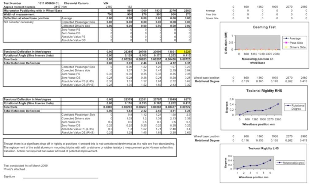
I just had mine rigidity tested by a qualified engineer about 4 week ago.
Here is the vitals....
68 Camaro
Art Morrison C5 front clip
full new rear frame rails (narrowed)
4 link rear with a panhard
DSE sub frame connectors. Welded in but bolted to the front clip not welded.
With no engine or trans in the car, and no interior or anything else (pretty much a stripped car). the rigidity test results can be seen below.
I am no engineer and cannot talk through this report in detail (maybe others can). All I do know is it now is just over 8,000 Ft/degree (on both sides of the car).
Note I have a full custom metal dash and console that is spot welded and runs all the way to the rear parcel shelf PLUS a metal hood liner that is also welded the entire way around the roof line. These are important as they will add a small amount to torsional rigidity.
 Chris Luxford
68 Camaro 632 BBC
61 Buick Lesabre - Daily Driver
06 Prius - Wife's a tree hugger !
04-27-2009 #10
Registered User
- Join Date
- Dec 2004
- Posts
- 203
Great discussion
Thanks to all who replied, this is a great discussion.
David, i was looking at Herb's book, i assume you mean Chassis Engineering. On page 96 he describes having someone stand on a 2by4 wrapped through the front frame, but this is impracitcal for a built car. I was wondering if anyone had any clever ideas of doing something similar with regular-guy shop tools with an assembled car?
Also hate to rain on your parade Cluxford but the readout you attached was in newton-meters rather than foot-lbs. Still, you have a pretty stiff chassis because with the conversion you are right about 6,100 lb-ft/deg (depending on side, they varied a little bit). This is the range David mentions getting to with properly-prepared first gens.
So if i "fix" three ends by putting them on jack stands, what is the easiest way to apply a known torque to an assembled car so i can get a number that could be compared to these other numbers?
Thanks!
Paul
04-27-2009 #11
Registered User
- Join Date
- Dec 2006
- Posts
- 285
Good catch...sorry I did know it was Newtom Metres (but 5am over here in Oz when I posted...hadn't woken up properly).
Chris Luxford
68 Camaro 632 BBC
61 Buick Lesabre - Daily Driver
06 Prius - Wife's a tree hugger !
04-29-2009 #12
Registered User
- Join Date
- Dec 2004
- Posts
- 203
still working on this
Still working on this, does anyone have an opinion once you fix the three corners whether you should load the fourth in bump or rebound?
Thanks again!
Paul
04-29-2009 #13
Registered User
- Join Date
- Apr 2005
- Location
- dayton, oh
- Posts
- 952
please note I have no idea what I'm talking about, just sort of thinking out loud here:
it seems like you could set a torque wrench to a known value, like 200 ft-lbs, put it on the 4th corner and measure how far it takes to get it to click. then do the math with the length of the torque wrench and the distance traveled. maybe?
04-29-2009 #14
Registered User
- Join Date
- Aug 2004
- Location
- Dunwoody, GA
- Posts
- 4,984
Paul,
How accurately are you wanting to measure? My response was in thinking you just wanted to see your parts working and to see what else you might be able to do. Is this about right or do you want specific weights and measurements?Trey
"The early bird may get the worm, but the second mouse gets the cheese."
~ Jon Hammond
1979 WS6 Trans Am stock LT1/T56 drive train out of my Formula. BMW M-parallel rims. C5/C6 brakes
build thread https://www.pro-touring.com/showthre...ghlight=begins
04-29-2009 #15
Registered User
- Join Date
- Dec 2004
- Posts
- 203
accurate
Ideally i'd like to measure accurately enough that it was repeatable and you could measure the difference before and after mods--if in fact there was a difference. I have a background in engineering and understand the physics and measurements that need to be made, but i don't have a lot of practical experience in how to make the measurements-which is why i'm calling those experienced guys out for some help.
There are way too many claims of "substantially increases torsional rigidity" with no data to substantiate the claims!!! I haven't seen these data from any of the manufacturers and think it would be useful for all if someone did these mods systematically and made careful measurements as they went.
As a specific example, the issue of subframe connectors has been beat to death here, but frankly has never been resolved because even in the giant sticky thread there is not a single scrap of data on subframe connectors that someone could use to make their own subjective decision. What SN65 did with the stang was amazing and well documented and measured, but frankly it didn't get to the heart of what i think a lot of folks would like to see--what about the bolt-on parts that 90% of us are running? The vendors are either not making these measurements to substantiate their claims or they are not publishing them. If i am wrong and even one of the ten or more sponsors that manufacture subframe connectors that claim they substantially increase torsional rigidity have published the data, i'd love to hear about it, and will probably start patronizing them immediately.
Paul
04-29-2009 #16
Registered User
- Join Date
- Aug 2004
- Location
- Dunwoody, GA
- Posts
- 4,984
You'll find that a lot of the claims come from doing simple tests like what I mentioned. Doing the mods and then jacking up the car in a specific manner will easily show that the parts work. To give you actual data though would require them to measure like you're doing and they aren't really interested in that because it takes time, money, and either they don't know it well enough or they know that 90% of the people out there don't know it well enough to care about numbers. I'm like you though. I'm coming into my last year as a mech engineering student. I prefer numbers and evidence to back up claims.
I was planning with my own car to do what I described. Only I was going to use a dial indicator to measure. It would be a while before I would need to get a lever arm and heavy weight onto the frame and measure accurately like Adams mentioned in Chassis Engineering. I'm expecting my Ttop car to twist easily for a while.
I'm not sure where the post is as it's been that long ago. However, XV posted some videos of the testing they did in developing their parts. One of them was a simple test in which they ran tape diagonally across the engine bay to form and x. They had the car on a shaker rig and to watch the x spread apart was amazing. After their parts where on it, the x didn't spread apart so much and the video easily showed this. You could replicate this type test with your car and just using a jack instead of a shaker rig. You may not be able to get hard numbers of x pounds per degree this way. To be able to say the tape used to separate this much but no only separates this much would be very beneficial to you. You could try out different front end braces to see what helps with this simple test.Trey
"The early bird may get the worm, but the second mouse gets the cheese."
~ Jon Hammond
1979 WS6 Trans Am stock LT1/T56 drive train out of my Formula. BMW M-parallel rims. C5/C6 brakes
build thread https://www.pro-touring.com/showthre...ghlight=begins
04-29-2009 #17 Registered User
- Join Date
- Nov 2008
- Location
- TN
- Posts
- 939
This is a really cool topic. I'd be interested in the results when your done.
I do have a suggestion about how you could attach the lever described in herb adams book. I'm not exactly sure of how the camaros are but I think you could chain around the subframe on the unsupported side and slide the 2x4 through. As long as the chain was fairly tight it would act like it was pressing down on the top(because of the chain) so it would measure the same. Just a thought.Benjamin
Twin Dusters
'72 Plymouth Duster "Aero Duster" project
'72 Plymouth Duster "Daily Duster" project
https://www.pro-touring.com/showthre...RO-DUSTER-quot
04-29-2009 #18 Registered User
- Join Date
- Nov 2008
- Location
- So. Cal.
- Posts
- 1,240
I think thats the reason these aftermarket dealers are not going through the steps. They may think if you are using bolt on frame connectors you are not concerned about torsional stiffness. Originally Posted by Chevy
Cause really, thats the weak link. Even if you pay attention the proper high torque specs for the fasteners it is still a slip fit for the connectors. Read SLIP fit. Slip will happen. Welded in connectors that are mended to the pan also provide much more torsional stiffness.
And even then its a matter of cross bracing. I welded in some beafy 2x4 heavy wall tubes to connect the rear to the front. Fully welded seams all along the pan where they met. Additional cross bars of the same 2x4" tube, fully welded to the pan and the rockers. And it still is not as stiff as it could be cause simply, Im still tying into the stock rockers, they are weak. . Thats where the weakness is. The frame is sufficiently stiff. If you were to do a jack test on the four corners of the suspension it would show some stiffness. But the problem is the body is still supported at the rockers.
So even though the frame shows some rigidness, buy itself, the body is still able to flex outside of the frame.
A quick check of that would be to jack the car up on the rockers. You may see some sag cause the body is not completely linked to the frame.
Maybe why some of the new cars with engineered uni-bodies are stiffer, they take the body and pan and make it ONE.
A way to combat that with our old cars is to make sure you have enough side bracing off of the center frame. They have to reach out to the rockers to support the body.
And when you do that you will have a solid platform, the "pan or plane" and the entire car will be supported by the horizontal pan. Then you can adjust the suspension to interact with the road from that plane. I look at it as a platform.
You have a few different horizontal planes. The base where the suspension pieces are located, bottom plane. The top, the roof line and the mid plane, belt line, where alot of your lateral weight transfer is. If you think about it spatially and tie the two panes (mid and lower) together then you have a great starting point to tune the suspension. JR
05-01-2009 #19
Registered User
- Join Date
- Dec 2004
- Posts
- 203
More great ideas and comments
I'm gonna keep working on this, thanks for the comments and ideas. I will post up here when i figure out a practical measurement method and get your opinions. Gonna try and resist the temptation of the bolt-ons until i figure out a method to measure the changes.
Cluxford, can you describe the set-up that the shop that prepped your chassis used?
Thanks,
Paul
05-03-2009 #20
Registered User
- Join Date
- Feb 2003
- Posts
- 71
Originally Posted by cluxford
pics of this?


 Reply With Quote


