

Results 61 to 80 of 89
Thread: derekf's 69 El Camino build
-
05-15-2021 #61

 -ɹoʇɐɹǝpoW-
- Join Date
- Jul 2002
- Location
- Mesquite, TX
- Posts
- 4,901

MWS was happy to swap out the incorrect liner - they didn't have an .024 one, but swapped the wrong one out for an .035 one. I hadn't installed it yet here, which is my excuse for these welds.
A little bit of grinding helps.
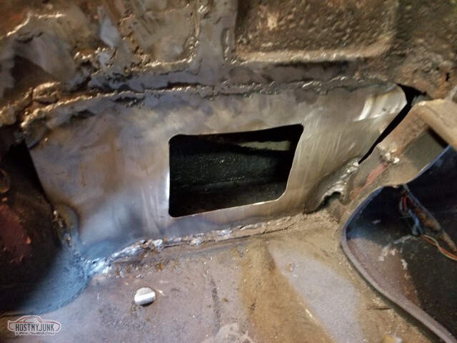
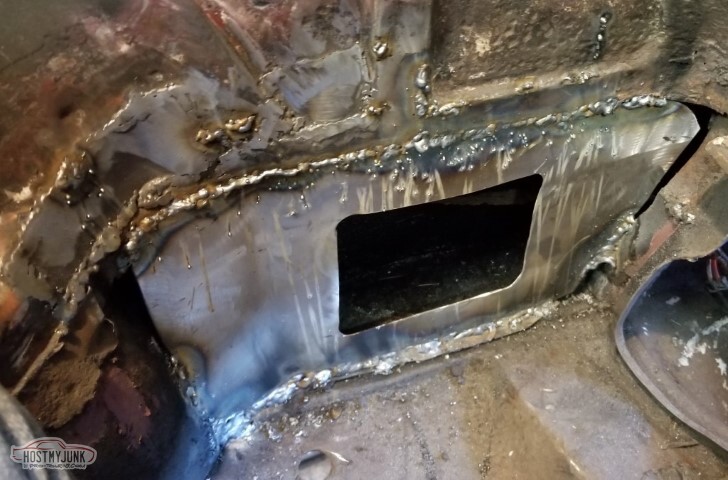
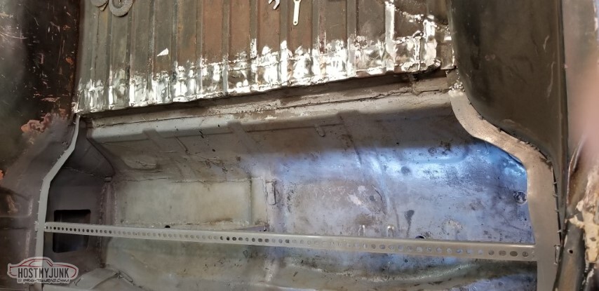
Patched the gaps at the front and back, and then added the crossbar brace.
A center post to help give it some strength.
Strong enough to support me, at least.
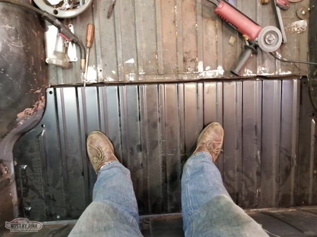
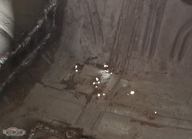
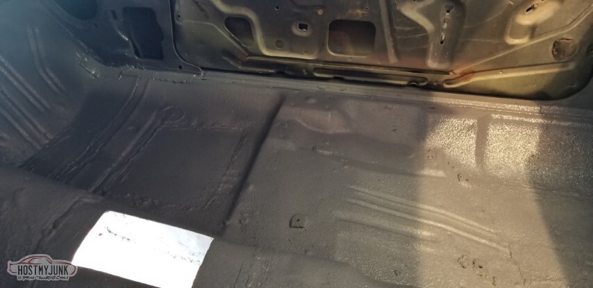
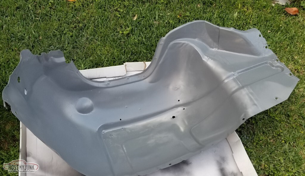
Primed the well.
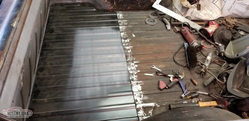
Time to install the new liner - this is the one I got mailorder (the .024 one); of course, I kinked it during install.
At least I had the .035 one from MWS.
Patched the middle of the (no idea what you'd call it - middle brace?)
Driver's side will be a little more involved.
.. and of course I failed to take any pictures in the "after" phase.</td>
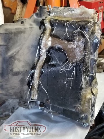
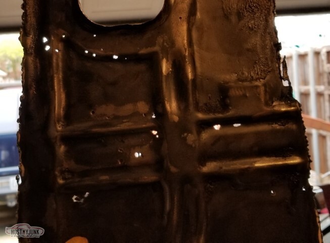
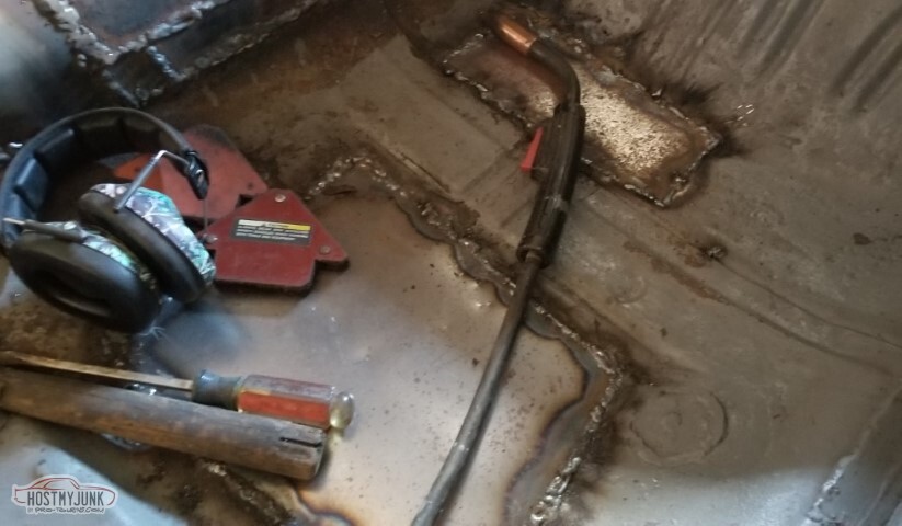
Filled the brace with POR-15. Seemed the best call for protecting it once it's closed up.
Wanted to verify that the smuggler's box would clear the brace. It does.
However, mine is no longer viable. Add to the shopping list.
Patched a small hole in the pass side wheelwell (at the end of the mid-brace-thing)
Idea: let's chop up the crappy patch panel that was in the front of the bed to fix this rotted area.
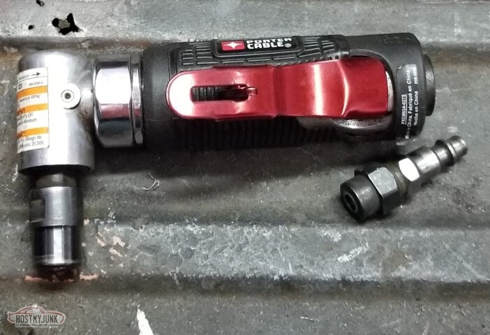
An aside: This Porter-Cable PXCM024-0275 is utter garbage. This is the second one I've had fail with just an hour or so of usage, and both failed in the same way - the air inlet breaks off.
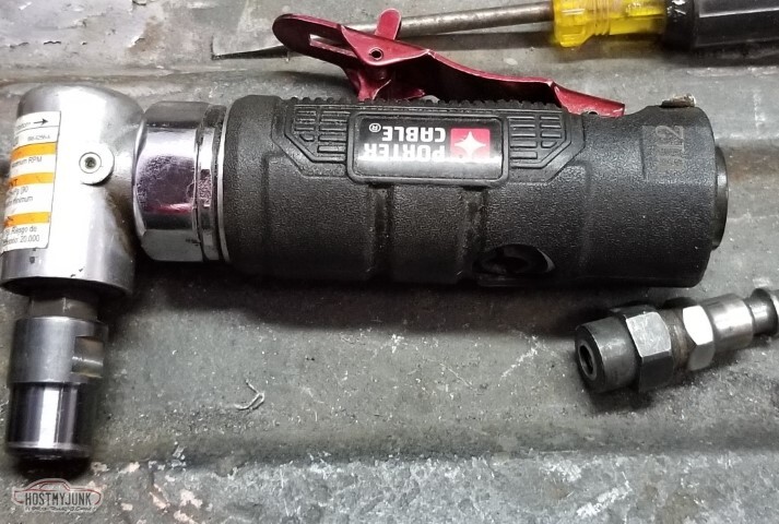
Also the head is not well secured; randomly reclocks itself during usage. Will not be buying any more PC products.
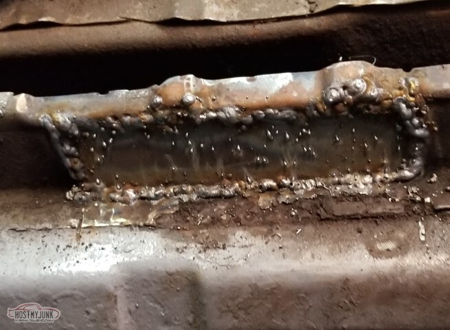
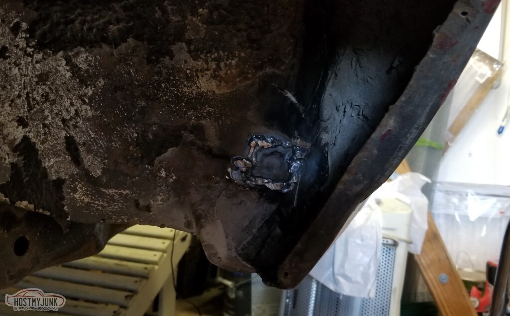
Time to start patching that gap. Seems to be working decently enough... which means it's time for me to be low on shielding gas again.
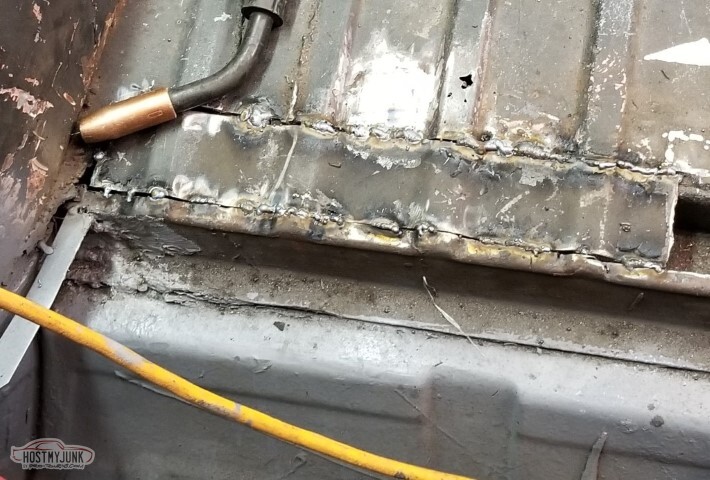
Powered through despite the low gas. They're not pretty welds, but I've not shown you pretty welds yet so I'd hope your expectations were correctly set in advance.
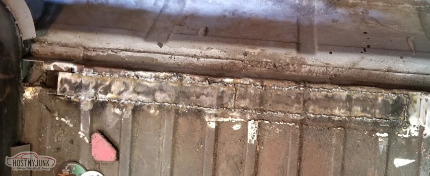
One additional patch for the very end. This one was an odd shape because it wasn't patched right last time (don't ask me why?)
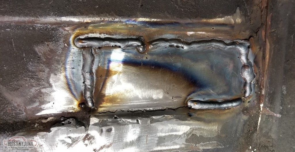
Partially ground. A reminder: It's not a showcar. It ain't got to be a showcar finish.
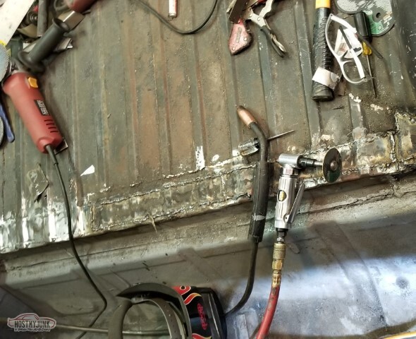
I went to spray real paint in here, but apparently everything is old. The "Chassis Black" can was solid. The single-stage black's reducer can was bone-dry. The old Chromacolor I'd painted the EC with in '99 or so both the reducer can was also dry... so I need some sort of paint for this.
Might as well put the lid on, for now.
New shielding gas tomorrow, probably.
-
05-15-2021 #62
-ɹoʇɐɹǝpoW-
- Join Date
- Jul 2002
- Location
- Mesquite, TX
- Posts
- 4,901
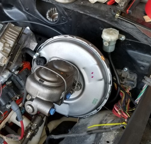
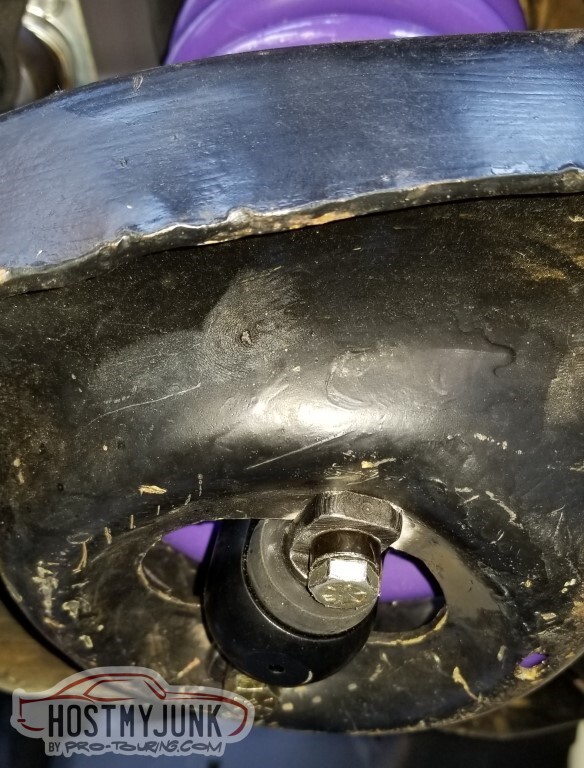
Does this really mean my brake booster was not the original but a damn near 50 year old reman?

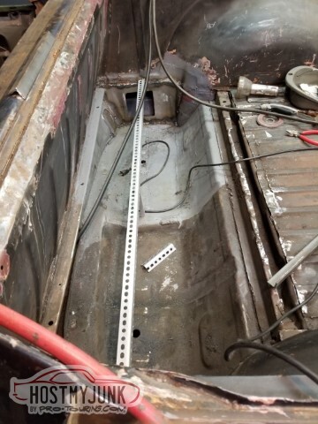
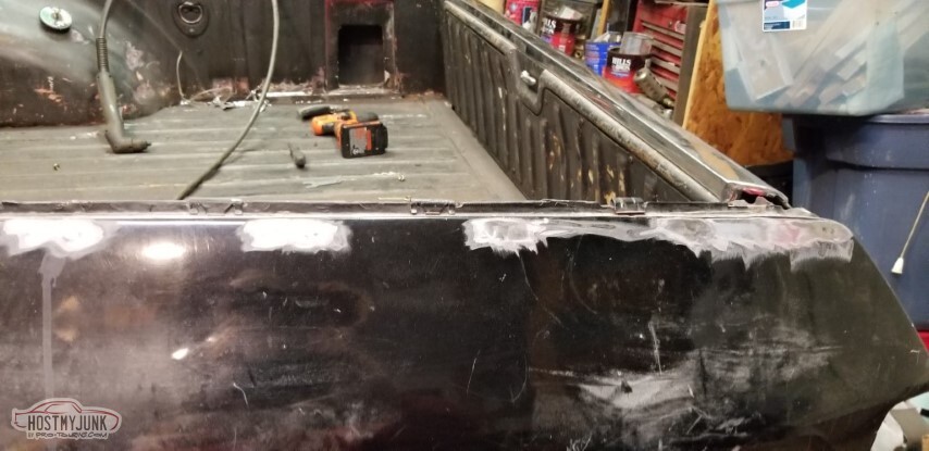
I cleaned out the back side of the bed.
Also - and not pictured - the front panel is ground and trimmed so it fits "flush", for certain values of "flush". I still need to finish welding the side flanges though.

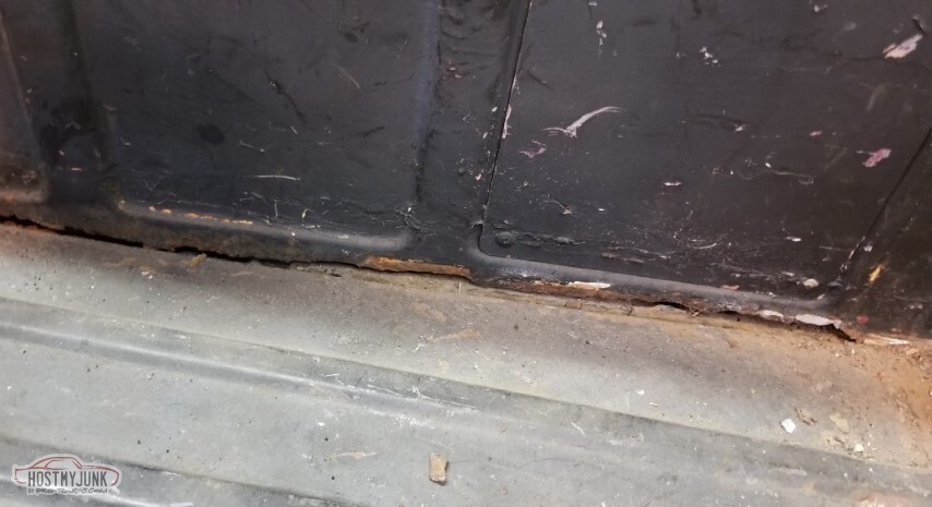
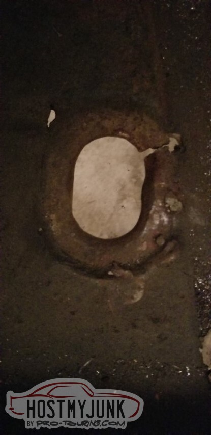
Start with scraping the putty stuff. Note the hole left center.

And here's the passenger side. The putty here needs to go.

Pass side, with the putty gone. Note that the bottom edge of the panel is also gone. That's... unfortunate.
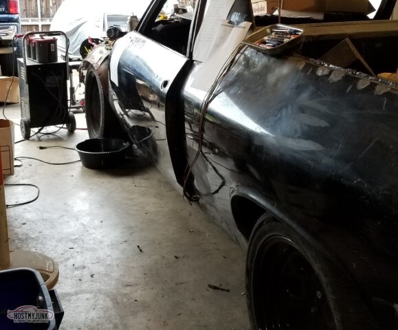
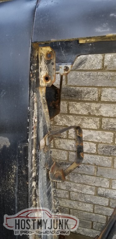
On the driver's side, without the putty. The rust on the side panel isn't as bad.
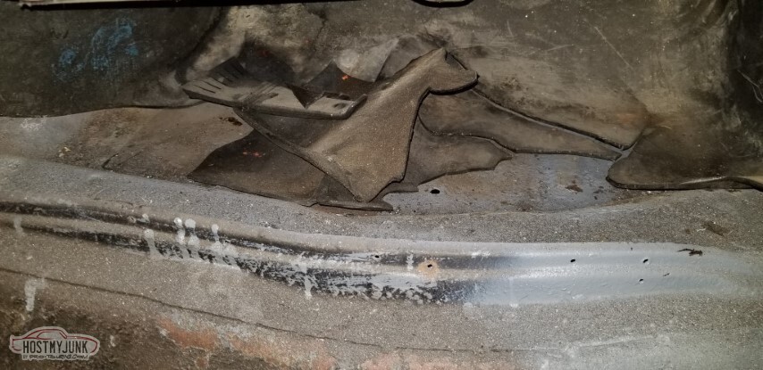
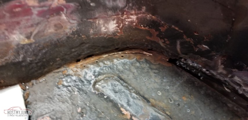
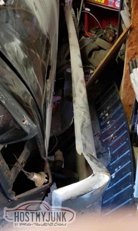
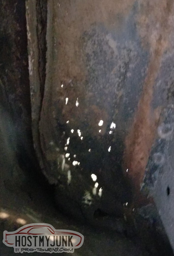
Rust bit next to/just behind the rear wheel.
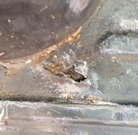
and rust at the trailing edge of the bed.
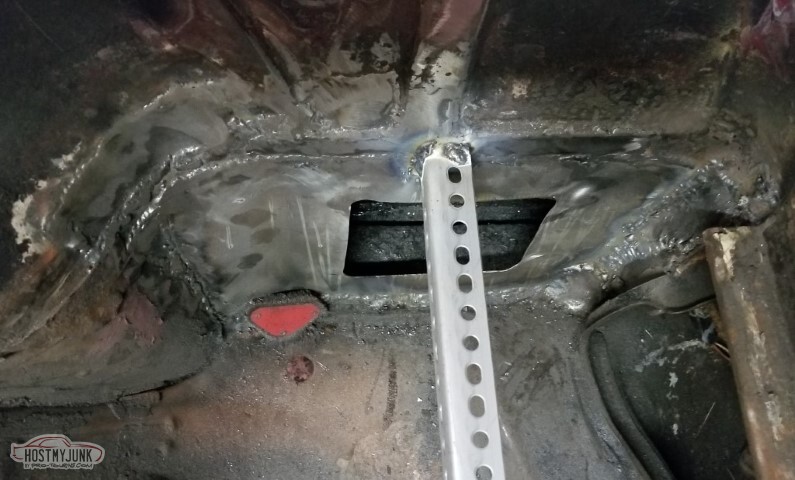
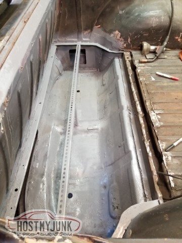
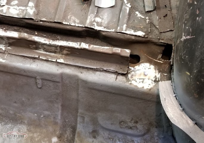
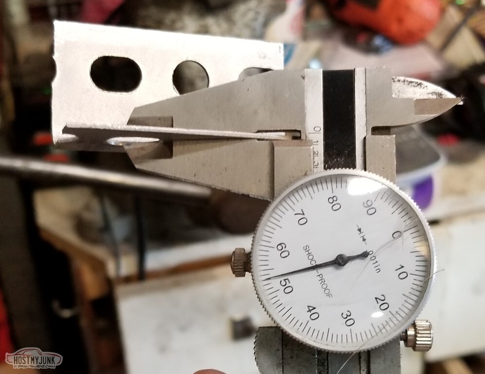
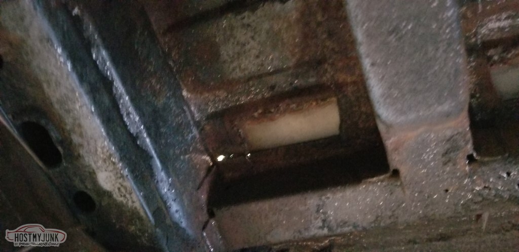
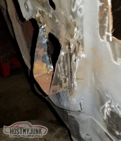
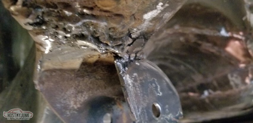
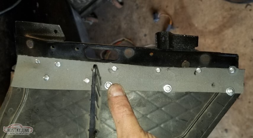
Shoved an L-square in there so I could tell how big the patch needed to be.</td></tr>
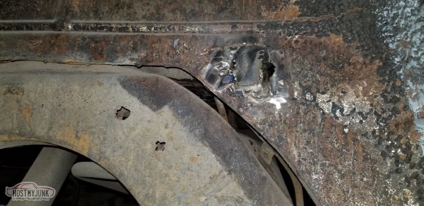
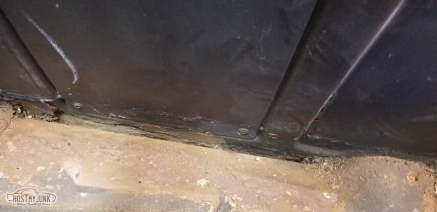
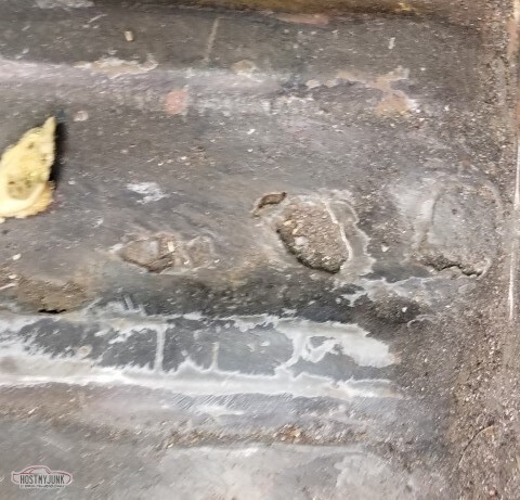
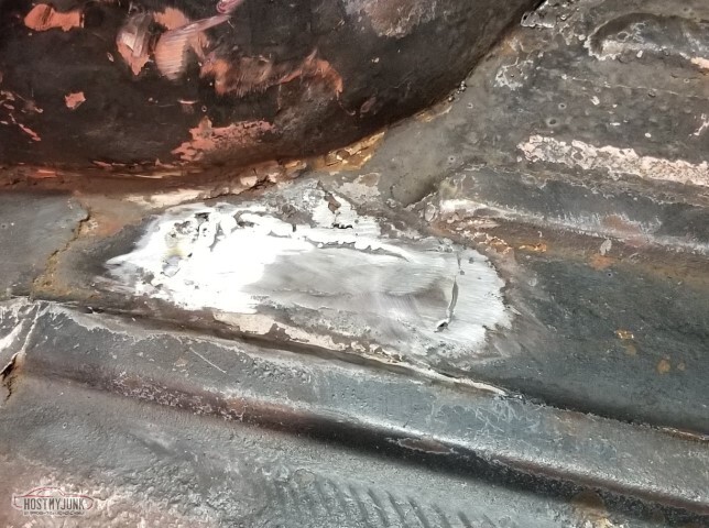
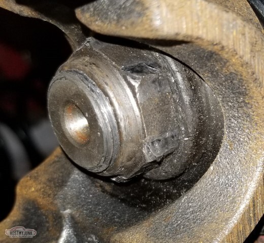
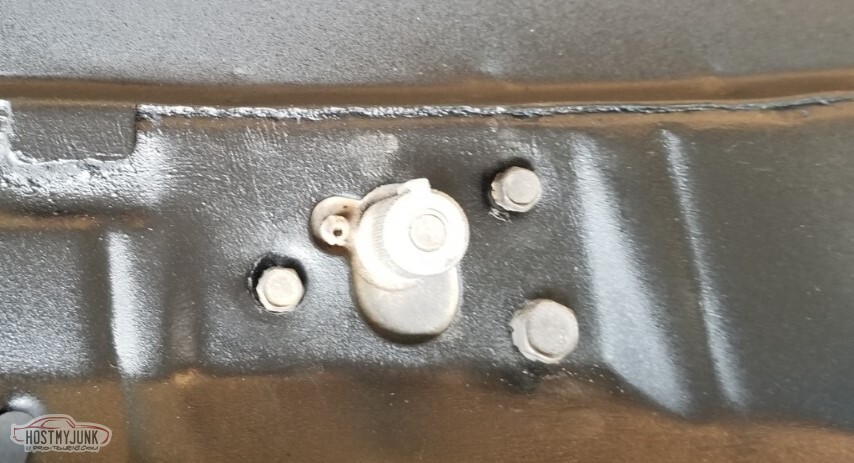
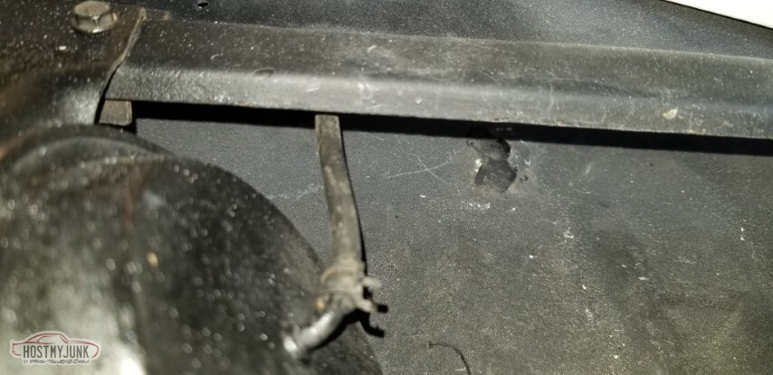
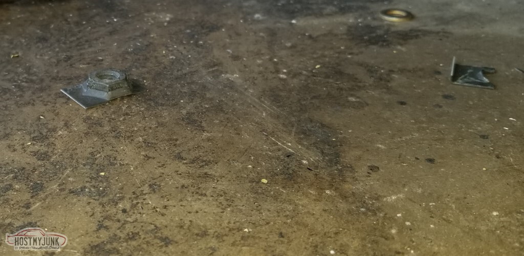
When checking the depth of the square... what kind of half-ass repair is this?
I mean - really - I know my first round on the car I did some seriously questionable repairs, but this is worse than what I'd have accepted even then.

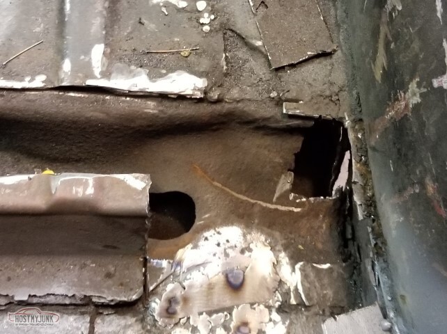
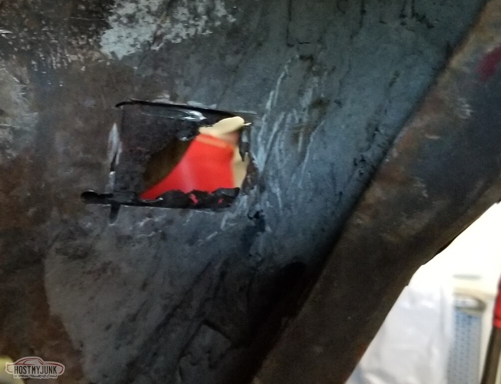
Probably the same kind of half-ass repair as this one.
Seriously, wth?
Still, probably mark this one as "won't-fix"; might just cut off the screw shanks.

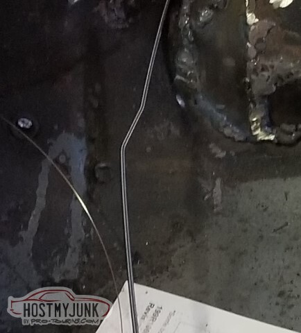
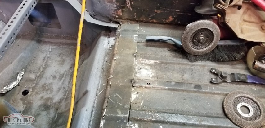
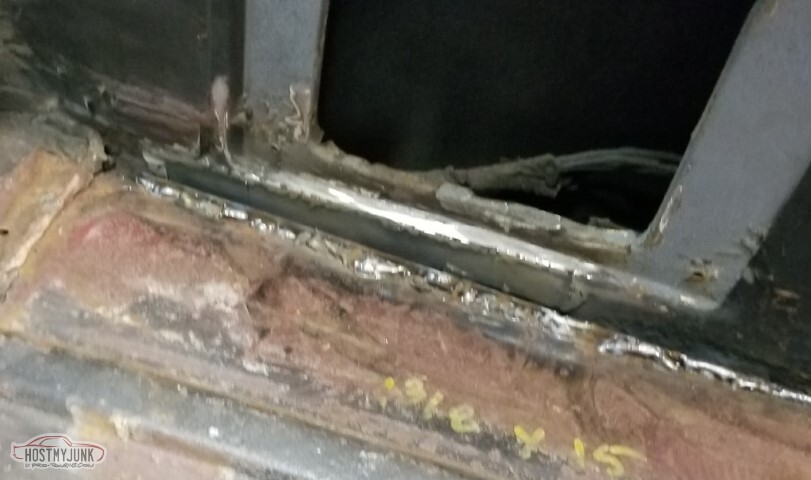
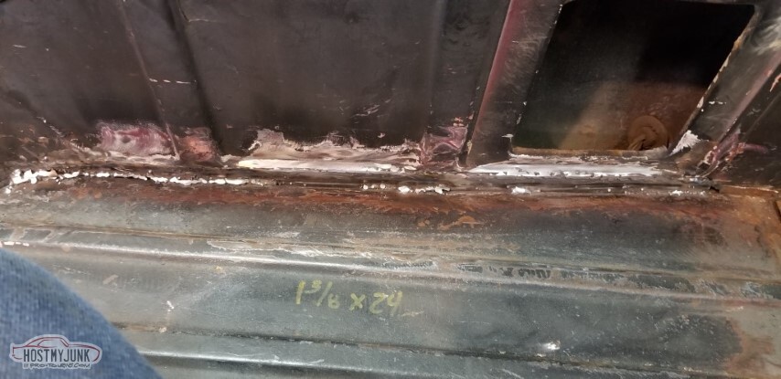
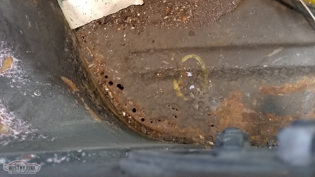
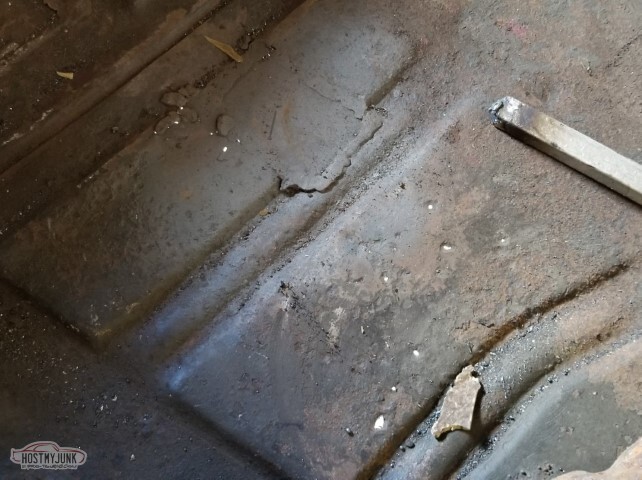
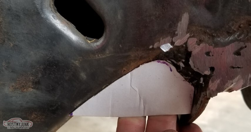
Same deal on the driver's side. Since I couldn't read, just use the yellow paint marker to get a distance.

Ooh.. math!
Looks like an inch and a half.

Also - I don't much like the way these stacked panel edges look but probably won't do anything about it.

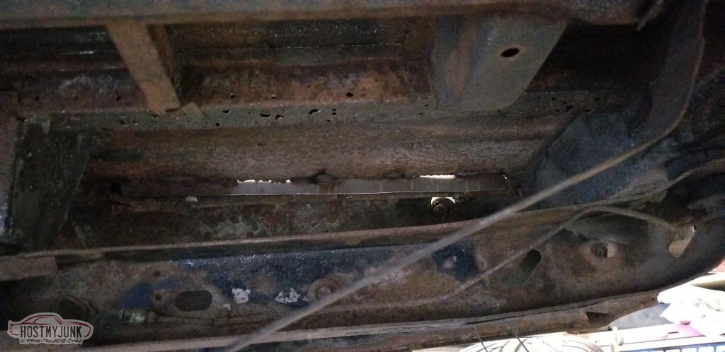
Hey look, a hole!</td></tr>

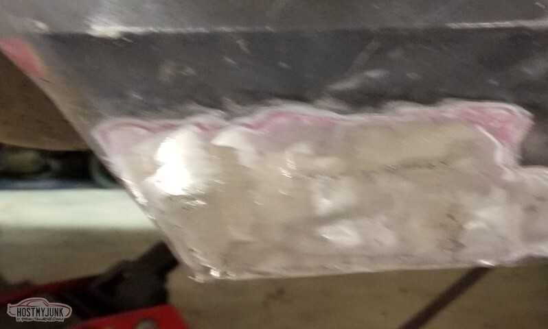
Patched.
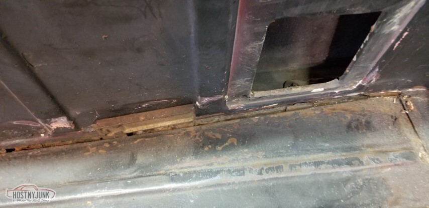
So I figured I'd just rebuild the flange , then screw them together to take up the gap.
That's not how it worked out - new flange, but the screws opted to not pull anything together.
I don't know yet how I'm going to fix this.

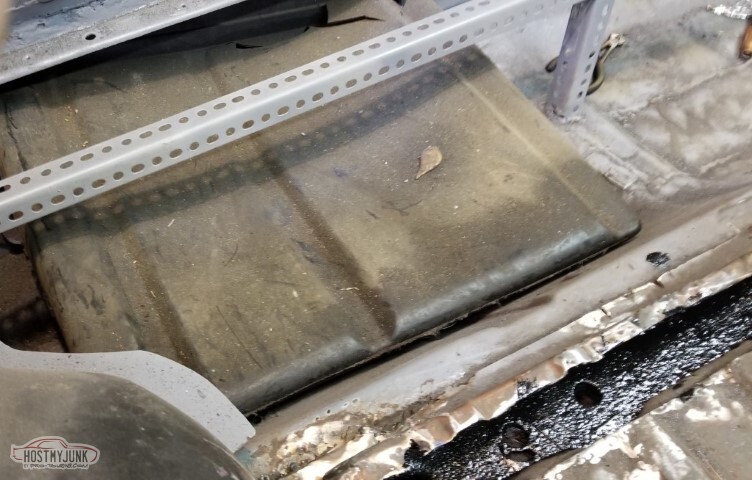
Opted for a different option on the pass side - single patch, for both the bed floor and sidewall. That should prevent that issue.

And, of course, "fix some rust" leads to "get more rust".
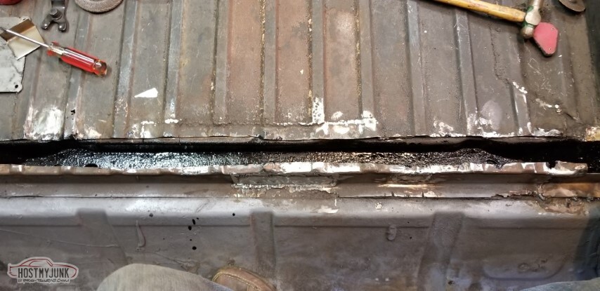
Filled these with weld bead, because that's how I roll.
Partially welded the seam. Need to finish welding.
Patch for the hole near the wheelwell.

Weld, grind, weld, grind.
Similar with the rust at the trailing edge.

Still to do:- Fully weld the side brackets for the front bed panel
- Finish the pass side rear panel cleanup
- Figure out a plan on the driver's side rear panel
- Wire brush lower quarters looking for hidden rust
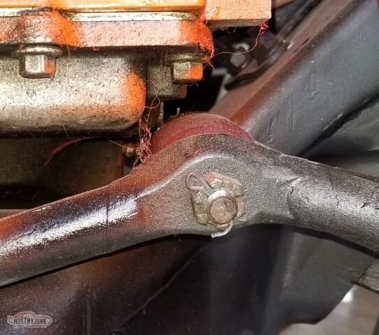
oh yeah also- Fix the spinny cage nut
- Close up the tonneau cover snap holes
- Pull drivetrain and weld up any pinholes in the patches
-
05-15-2021 #63
-ɹoʇɐɹǝpoW-
- Join Date
- Jul 2002
- Location
- Mesquite, TX
- Posts
- 4,901
This update is not merely a rust repair update, which is not to say that the car doesn't continue to be made out of weld bead.
Broken into sections for ease of following:
Rust repair, continuing the unending saga of the car that will end up made entirely of weld bead (I'm rapidly approaching the point of "won't fix" on additional rust - if it's not structural nor won't affect the paint... maybe don't care so much now)
You know the saying, "don't ask any questions you don't want answered"?
"Is there any rust behind the driver's back wheel" is one of those questions. The answer is, predictably, "Yes, yes there is.".

The fix is, as it always is, cut and replace.

Done.
While the welder was out... (yes, I'm still having gas flow issues)
Closed up the holes from the tonneau cover.

Closed up the driver's side bed gap. Would have preferred that it just butted up but no such luck.

Clutch hydraulics!<p>
Cleaned up the weld bead mounds on the firewall some...
... so that I could fabricate a closeout for the clutch master cylinder rod - I dont't want outside air getting in; this will be welded to the firewall and sealed to the backside of the mount. Still need to cut the hole for the rod to go through.
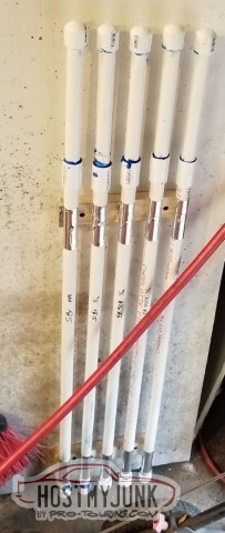
I made a thing! I'd seen a video where they did something along these lines. My TIG rod storage needs were much simpler; this is 3/4" pipe.
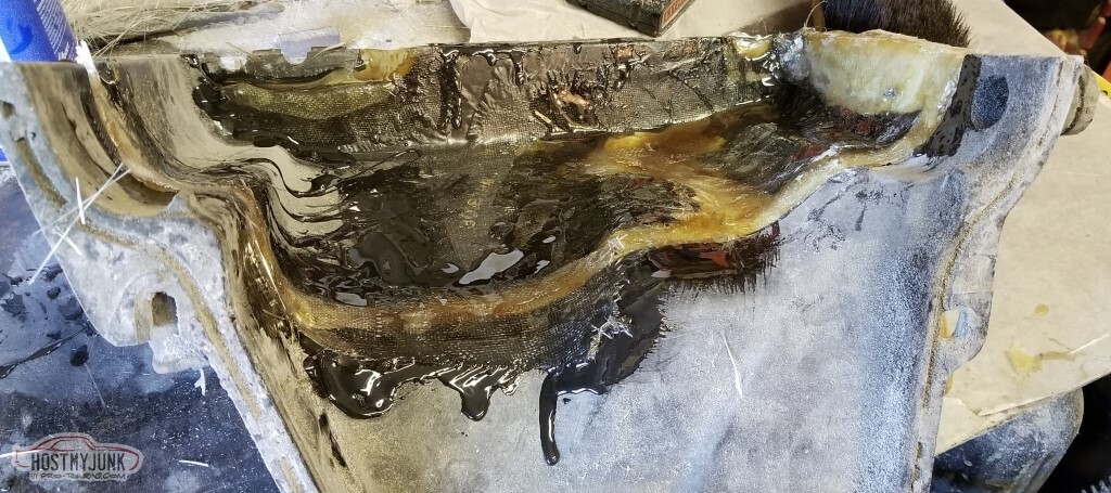
It's time to make progress on the AC box.<p>
So I think I've got A Plan on the AC box - using the F-body evaporator's closeouts as part of the new box has made it all start to just work.
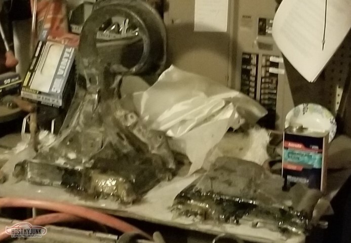
Of course, there's damage that needs to be fixed too though. Here I'm fixing where a hole was in the original box. Bottom (far right) edge is also missing in this chunk.
A little additional backing on the left, next to the black plastic thing. Obviously a lot of smoothing and additional work needed here.
Inside view of the lengthened side.
Bolted it all together and used some of the aluminum tape as a backing for the repairs. It actually worked really well! This is, of course, only the initial layer. More to do.
and then the bottom of the "done" side with it all bolted together.
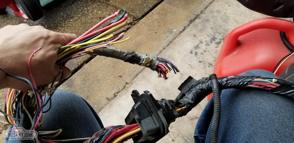
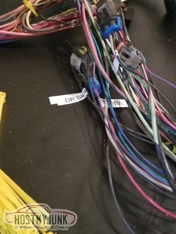
Wiring is also a concern, because of course it is.
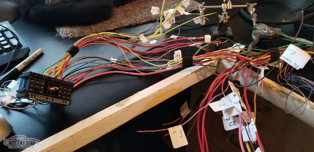
Dragged the harness-chunks out just to lay them out, see what I'm working with.

I'm working with things that were randomly cut...
... things that are crushed...
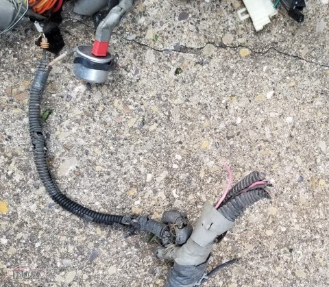
... things that are torn...
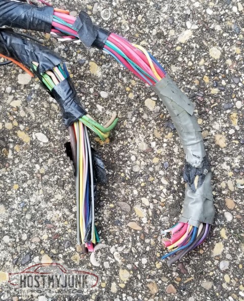
... and things that are maybe a little of each.
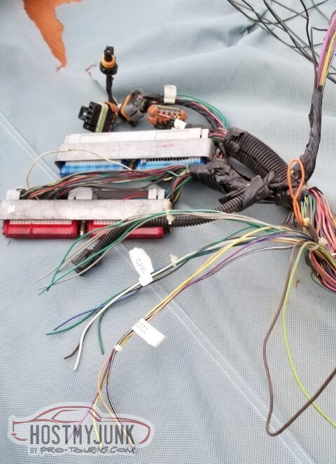
A preliminary pass at labeling some wires. These are the C210/C220/C230, bundled with the wires I know goes with each, and then the ones that I am not quite sure from the colors also sitting out there unbundled.
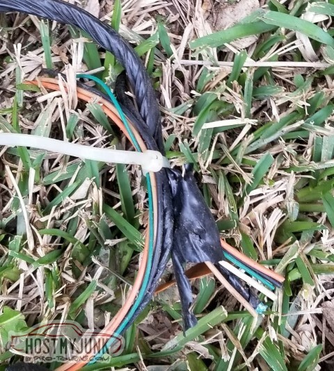
Another case of "things that were cut"
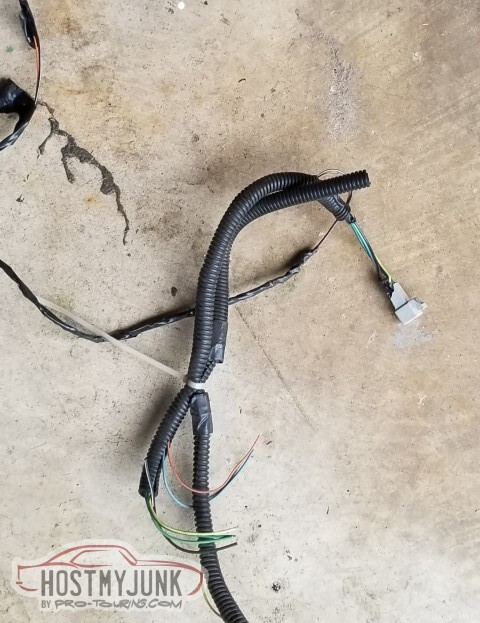
From research I have learned that the braided wires are from the wheel speed sensors.

Unfortunately for me, I believe that these....
... are the other end of this. Would have been too easy to have the socket to just plug things together.

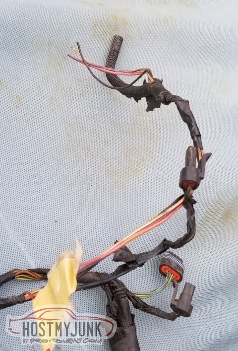
Spent a decent chunk of time pulling the loom and the electrical tape wrap off the front lighting harness; figure I'll be removing the ABS components and might as well do it proper. So much research to do, so many connectors that are cut off or torn free and I need to figure out their purpose.
ABS and airbags will be deleted. Emission bits too. Otherwise not sure yet.
I found this, by which I mean that I bought this years ago, when I was smarter.
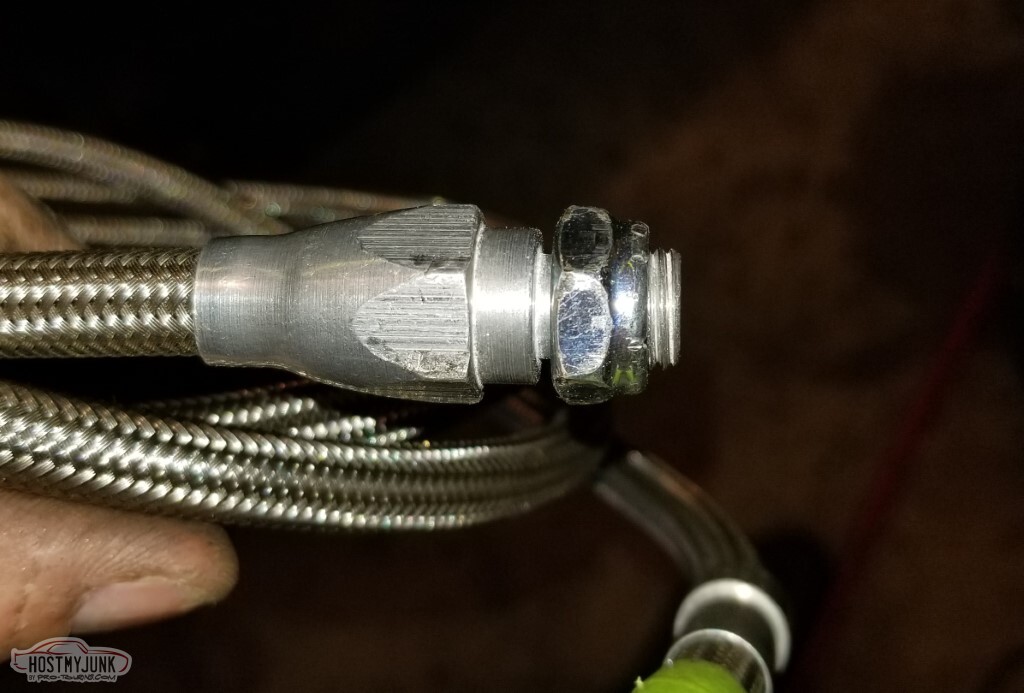
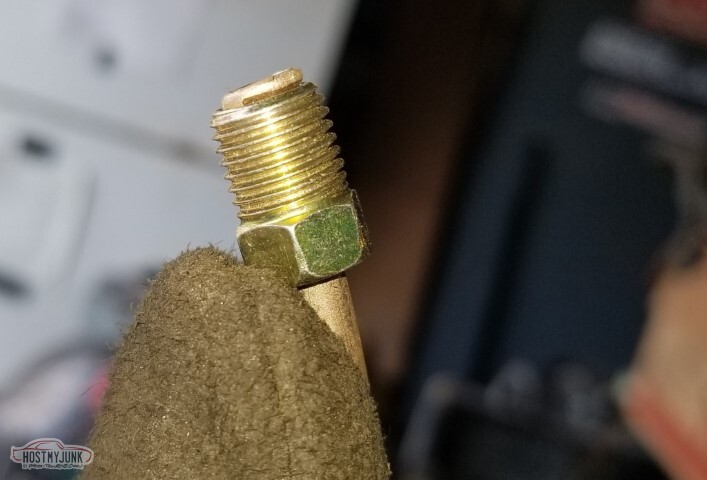
The brake hoses are 69 Chevelle front disk brake hoses - apparently the difference in size between a 10mm banjo fitting and the 7/16" we have here are small enough that the copper washers will just work to seal it.
This leads me to think that rather than a weird 10mm to 3/8x24 adapter in the back with 97 Camaro rear hoses, I can use something short and SAE sized.
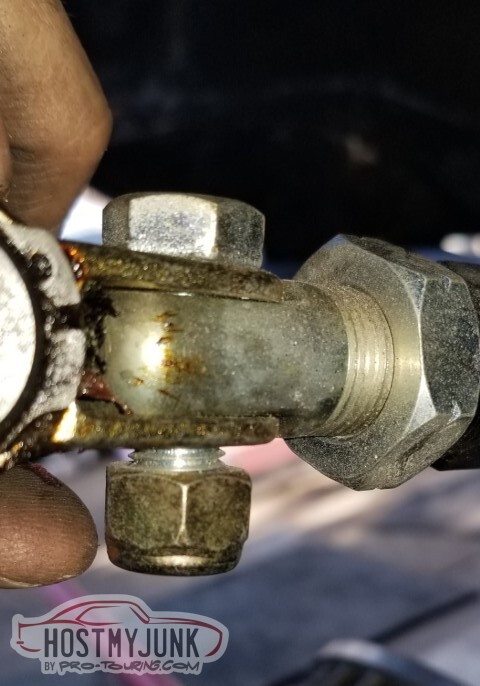
I have a concern about the master cylinder. Since I'm using the El Camino booster with the F-body master there's question about the rod length.
From a flat across the back of the MC, the pin recess is about .582.

Similarly, and from the same flat, .657 to the mounting flange.
Across the flange of the master, the pin is recessed .295

And for calculation purposes, that flat is .053 thick.
So - check my math please.
The pin recess is .529 from the flat (.582-.053)
The flange is .604 from the flat (.657-.053)
The pin is recessed .242 (again: .295-.053)
This means the pin recess is actually .075 proud of the flange (.604-.529) so has a gap of .167.
I liked the numbers better the first time I measured; a pin recess of .518 and a flange depth of .649 made the recess .131 proud, plus a pin recess of .221 meant I had a gap of .09 (which - and I need to recheck my thinking - led me to believe I was .07 too long of a pin, and needed a spacer for the MC away from the booster).
Obviously I need to remeasure and remath again.
2021-05-11 edit: Please don't check my math. It's wrong.
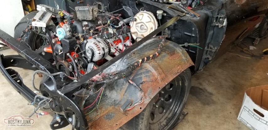
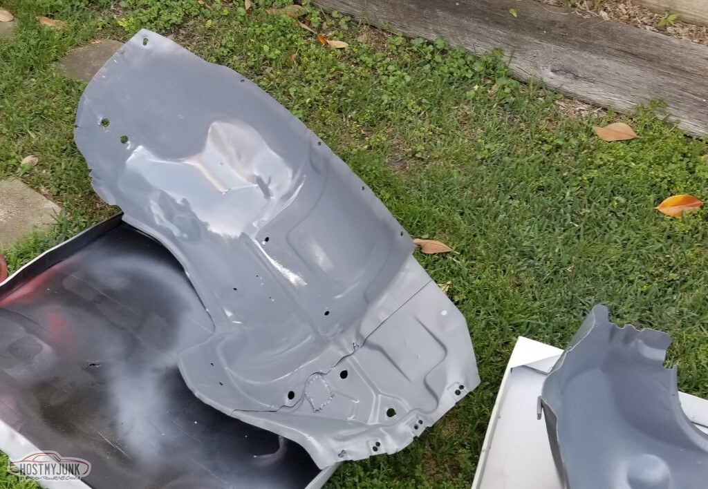
Also I pulled the fenderwells and core support out from the side of the house, where they've been sitting in the mud for a decade.
Yeah. The mud.
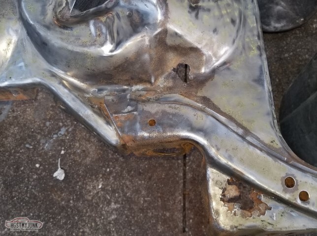
They actually came through it pretty well. Here are two rust areas on the core support but I think they were bad when they came off the car in 2006 (post 13: "I have some rust issues on the core support over by the battery").
The fenders were not in the mud and they appear to have weathered the weather just fine.
The hood was also not in the mud. There is a decent amount of rust on the underside and I am not quite sure why. It may be from its previous life in the salty north.

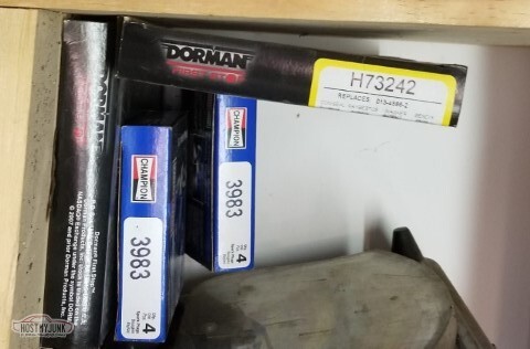
I bought things:
Most of the parts for the fuel system have shown up. One is backordered and one is just slow, and I think I ordered 2 of one fitting where I actually needed 2 of a different one.
Also ordered a pinion depth tool for the rear-end rebuild. That task scares me quite a bit.
Got a "Needle Scaler" at HF. It works pretty well but I did not expect the needles to be a consumable. Got about a quarter of the under-bed scaled.
Also picked up some implement paint at Tractor Supply. In theory I'll spray primer and the implement paint on the underside as I go; in reality, the gas water heater is awful close to where I'd be spraying... makes me a little nervous.
-
05-15-2021 #64
-ɹoʇɐɹǝpoW-
- Join Date
- Jul 2002
- Location
- Mesquite, TX
- Posts
- 4,901
There has been a terrible mistake.
Well. Probably more than one.
We already discussed the damage to the forward harness. I went to a junkyard and found a car (a Pontiac 6 cylinder, at that) and got a new C200; had to re-pin a few things to line up with the V8 bits.
Not pictured: I scanned in about 170 pages of connector drawings and schematics from the Helms manual. I actually found some errata, not that I know who I'd tell; the books are almost 20 years old.
I also made a master spreadsheet with the circuit numbers, and what each end of each wire is.
I saved off a set of the completed scans, I'll make my notes and change the things that need changed (remove ABS, EGR, etc.; change the plugs for AC fan, headlamp, etc.), then print and put in a binder for future reference.
In this picture I started labeling the wires in the damaged harness as I could probe them and figure out which is which. I probably should have just found an undamaged V8 Chevy forward harness - there's at least one more junkyard run coming.
Started connecting the new C200 to the cut portion.
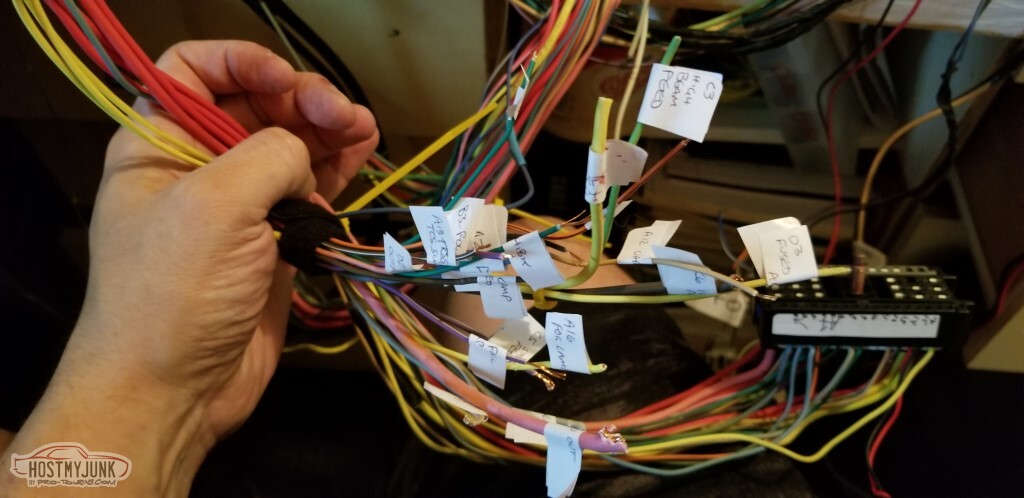
Lots of labeling. The labelmaker ran out of tape, so I moved to handwritten.
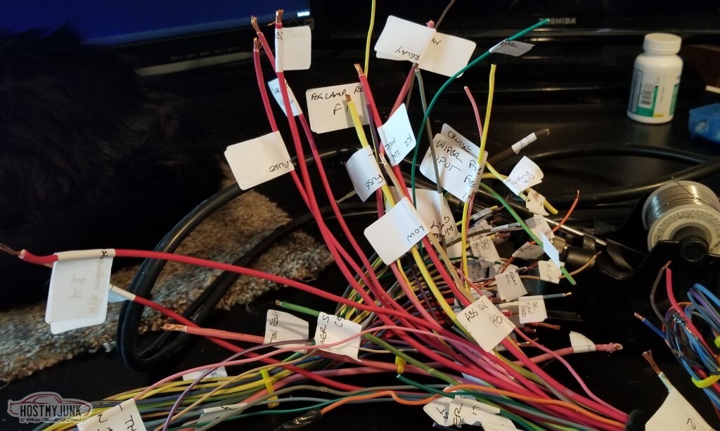
The process of combining both ends is very time consuming.
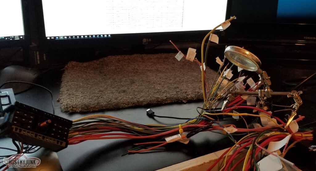
At least I could use this for both the soldering and the heatshrink.
It is progress, of a sort. There are issues that I don't quite understand yet.
For some reason, this connector is not just to hook the front harness to the mid harness. The ignition switch and the instrument panel fuse block are on opposite sides of this block. I think there's more missing connectors but I can't tell; surely the General didn't expect solder and heatshrink to replace a front harness. It looks like most, if not all, of the remaining wires coming through the firewall here will go to things other than the C200 block.
So really this update was just so I don't get out of the habit of updating; the work progresses, slowly. The wife suggests that I do garage while it's cool out, and worry about this when it's hot out. She's probably right.
I've got the pinion depth gauge, the bearing race driver, and the bearing splitter I need to do the rear axle... it just scares me.
Also need to finish the needle scaling of the underbed, to powerwash the fuel tank and remount, to finish welding the bed front panel flange, to figure out why my MIG is not welding well. Much to do. Plenty of time, but much
to do.
-
05-15-2021 #65
-ɹoʇɐɹǝpoW-
- Join Date
- Jul 2002
- Location
- Mesquite, TX
- Posts
- 4,901
Thought I'd taken more pictures.
The repair-modifications to the AC box continue.
Cut the hole for the clutch master, and test-fit the mount.
Since I don't want to try to figure out a rubber seal for the mount, let's instead adjust the body so it seals against the plate.

Oh yeah. I forgot; somewhere in there I forgot how to weld? These welds are abysmal and I still don't know why.

I also cut the hole for the wiring harness connector (2.5" h x1.85" w). This also looks uneven, maybe I should quit while I'm ahead.
Tomorrow is junkyard for the remaining missing connectors. Hopefully.

Turn attention to: Needle-scaling the rear underbody. The needlescaler is a wonderful tool to remove dirt from the underbody and move it to my hair.

Rear bumper removed. Brackets added to the "need sandblasting" pile.
The scaler is not nice to thin metal. Note the needle-scaler-pin shaped holes. Added to the "fix this" list.
More of the same at the back side of the driver's rear wheelwell.
These both fall in the category of "I need to get the welder working correctly soon".
Needlescalery

Up to over the rear axle. Note the rust holes in the brace.
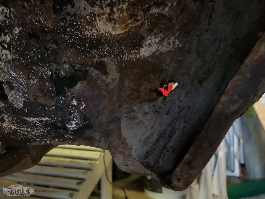
From the underside, the rust holes in the bed behind the wheelwell are more obvious.
Another new hole the scaler has shown me.
Seems like I have some work left to do on the pass side too.
-
05-15-2021 #66
-ɹoʇɐɹǝpoW-
- Join Date
- Jul 2002
- Location
- Mesquite, TX
- Posts
- 4,901
So - the welder.
It appears that welder gnomes have attacked my garage, and set the polarity on the MIG welder backward. Surely it's not been wrong for better than a decade, because it had been working up until recently.
Regardless, I changed the polarity to electrode positive.
First test bead: dead silent, just a really bad blob falling off the workpiece and onto the floor. The google says silent welding is "spray mode", but the settings are set to match the details on the placard.
Maybe the voltage switch went flaky?
A: 19.25v
B: 22.25v
C: 26v
D: 29.6v
No, those seem realistic.
Let's fall back and try going from C-4.5 to B-6 or so, reducing gas to 15cfh.
And then It Just Works.
So - there's a little remaining rust. Here's most of it, or at least where most of it used to live.

weld weld weld your car

Similarly, in the wheelwell.
I have welded. I did not bother doing much cleanup, because this area Just Does Not Have To Be Pretty.
At least not right this second.
Just as a playing thing, here's a patch that had poor penetration. Penetration is good now. Still need to clean it up.
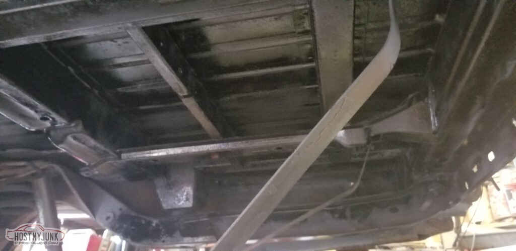
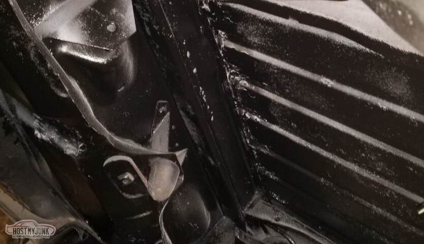
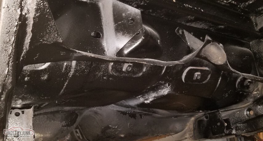
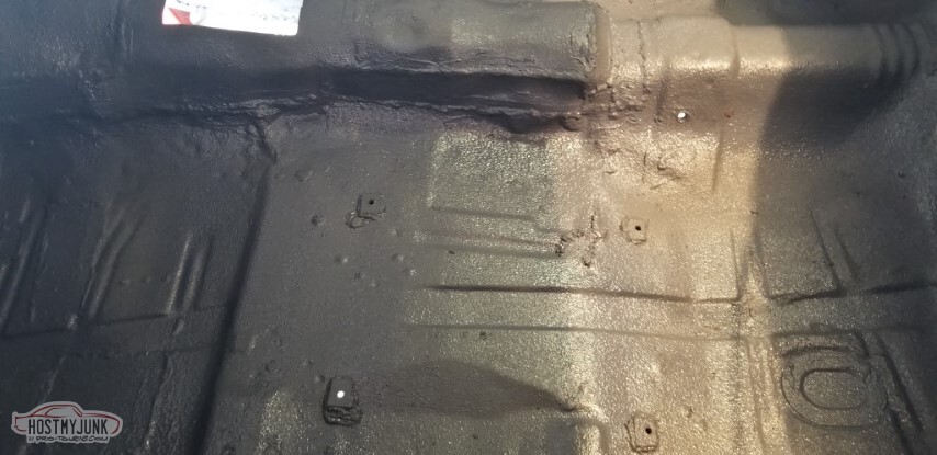
I shot some epoxy primer on the rear area of the underside. You can see just how bad the bed bracing is. Not going to worry about this right now; will pre-emptively give myself something to beat myself up over later.

Similarly, moving forward. Over the rear axle is about where the priming stopped.
And then real paint. This is "Majik" implement enamel from Tractor Supply. Seemed to spray well enough, not so good color coverage, might be user error.
Same idea, stop before the rear axle.
It's "matte black" flavor, the hardener is supposed to add a little gloss; we'll see how well it works.
-
05-15-2021 #67
-ɹoʇɐɹǝpoW-
- Join Date
- Jul 2002
- Location
- Mesquite, TX
- Posts
- 4,901
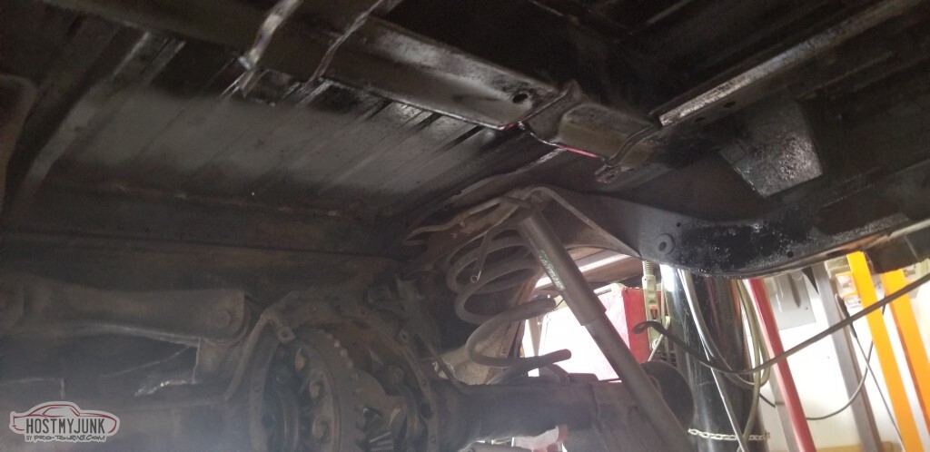
I have been dreading this, mainly because I have *no* idea what I'm doing here, and it'll be really easy to screw it up. So, it's time to do something wrong.
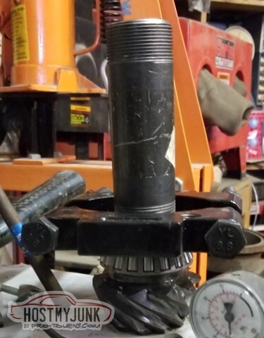
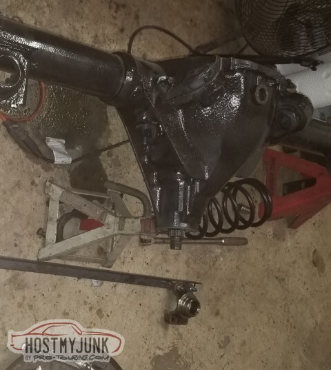
Pulling the axle bearings is the first step.
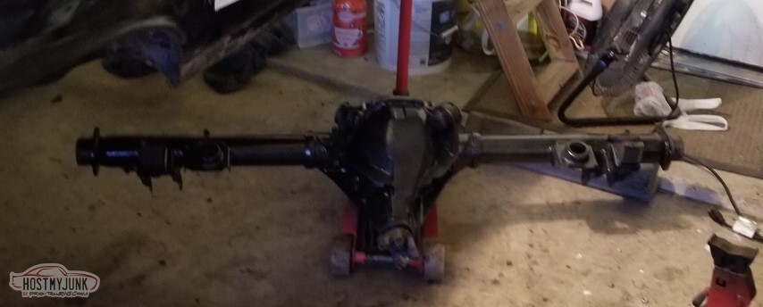
UCAs and LCAs, and shocks, and springs, and brake hoses are the next step, with those disconnected the whole assembly comes out.
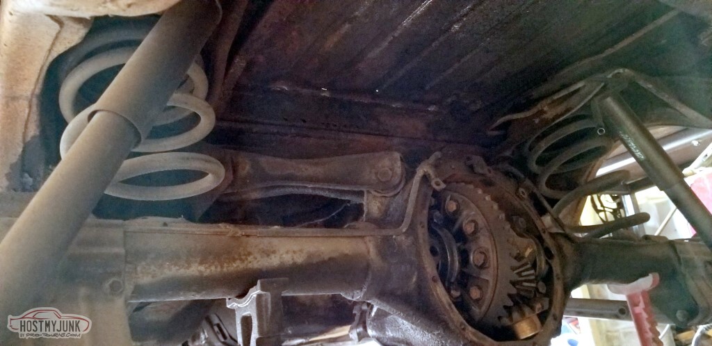
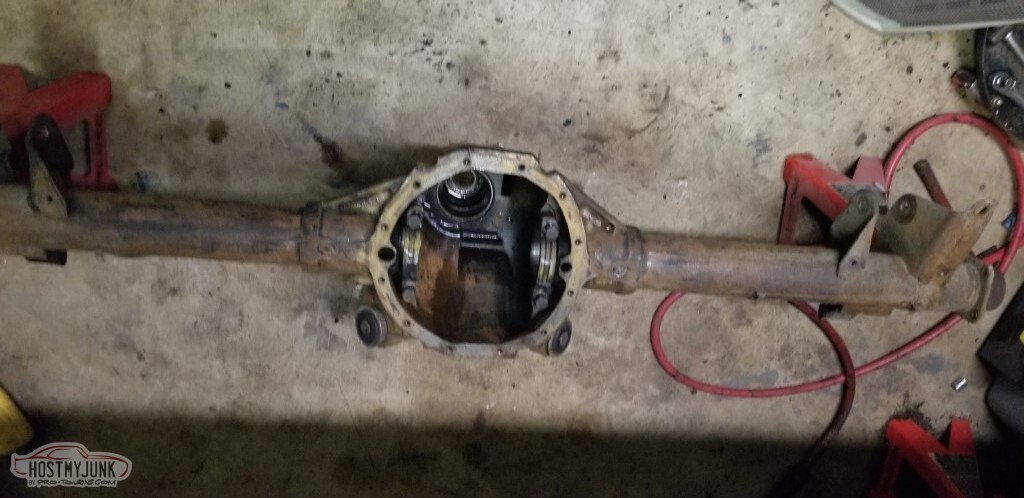
Carrier is a 2.73 open.
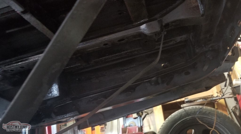
Lots of room under the car without the axle and gas tank

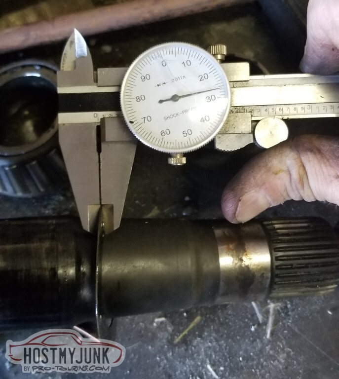
Driver's side shim is .238
Actually, pass shim is also .238.
 <img src="http://www.derekf.com/images/2001030005.gif"></a></td><td>
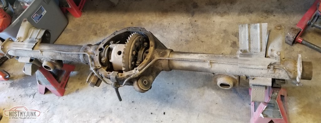
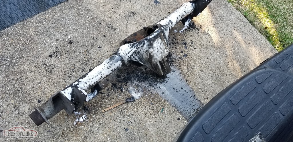
With the housing torn down, the grease and dirt can be removed. Scrub, degreaser, soak, rinse, repeat.
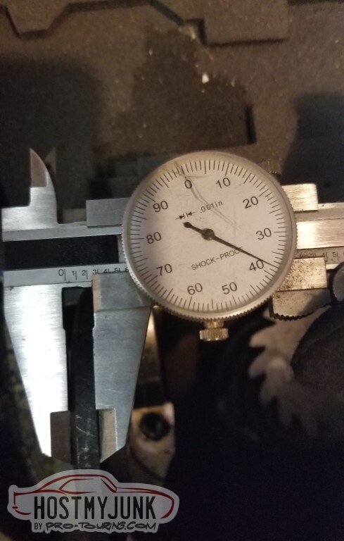
Meanwhile, the pinion shim is .026.
Cleaned the dirt and oils off, not going to bother trying to polish it up. Good enough for painting.
Primer is Summit epoxy primer.
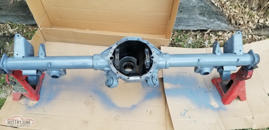
Paint is a Tractor Supply implement enamel.
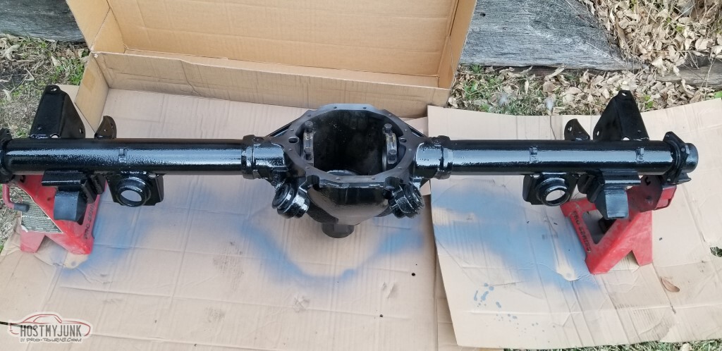
Axle stamping is "KD 06 9B". KD indicates - as expected - 2.73 open, in this case.
That might actually be 0619B. Chevellestuff says that'd be made 19 Jun in Buffalo.
 ;
;
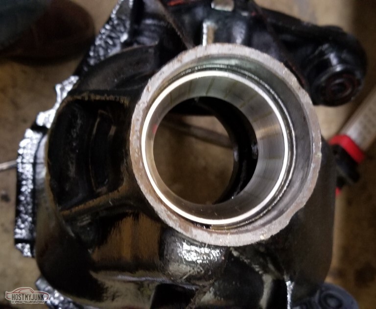
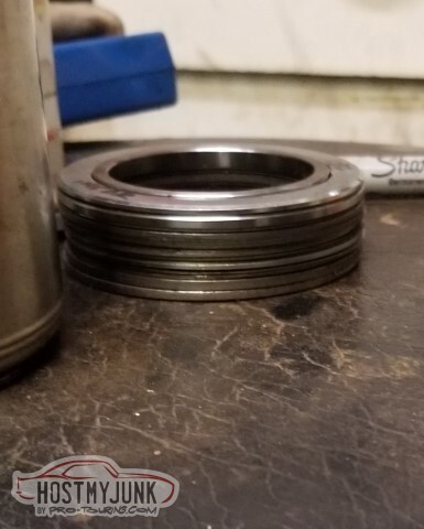
Had quite a bit of trouble getting the inner bearing race installed. Here's the stopping point I got to.
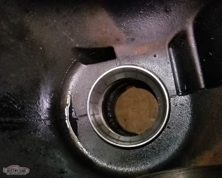
Front race went in easily enough.
Went ahead and put the bearings on the Truetrac carrier.
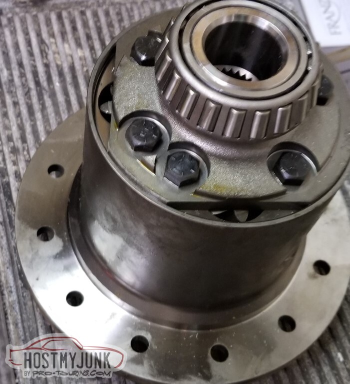
Installed the 4.10 ring gear. I was surprised to actually take a part from the pile and attach it to another part. I'd picked up some ARP bolts for the ring gear to use instead of the ones that came in the Summit install kit.

Despite the best efforts of the bearing driver, I was able to get the inner race installed. I actually had better luck using the flat side of the driver rather than the tapered.

The tapered doesn't *really* fit the race.
 <img src="http://www.derekf.com/images/2001030017.gif"></a></td><td>
This is the set I'd used. They're from HF.
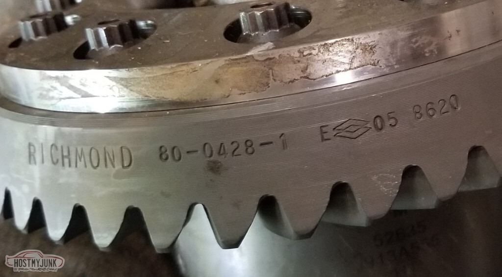
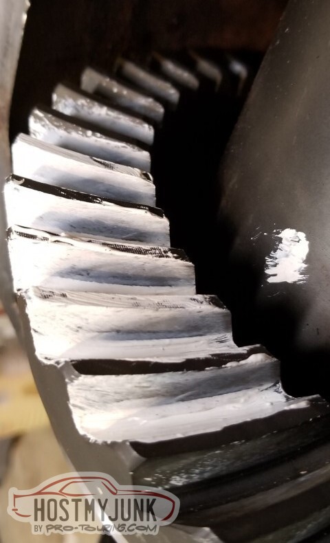
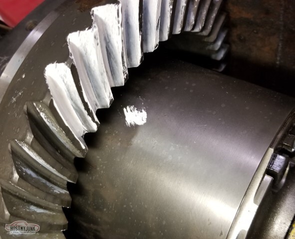
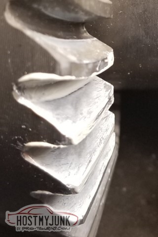
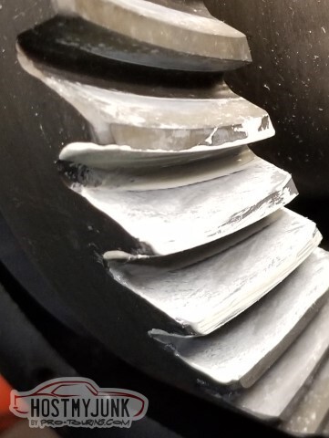
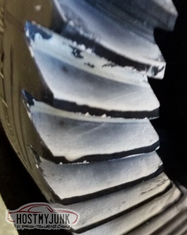
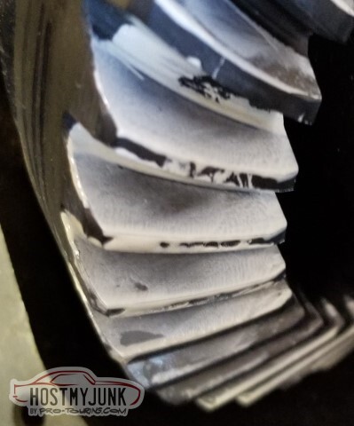
I bought the gears in 2005. They sat on a shelf since then, and surface rust has taken hold.
From the Richmond Gear instructions:
"Each set of gears is a matched pair which has been prerun on a gear test machine" .. "since all gear sets have been run-checked, specific settings are supplied with each ring/pinion pair"
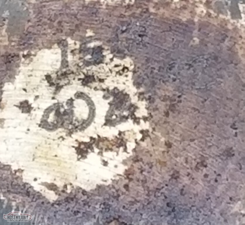
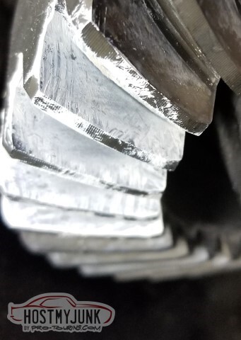
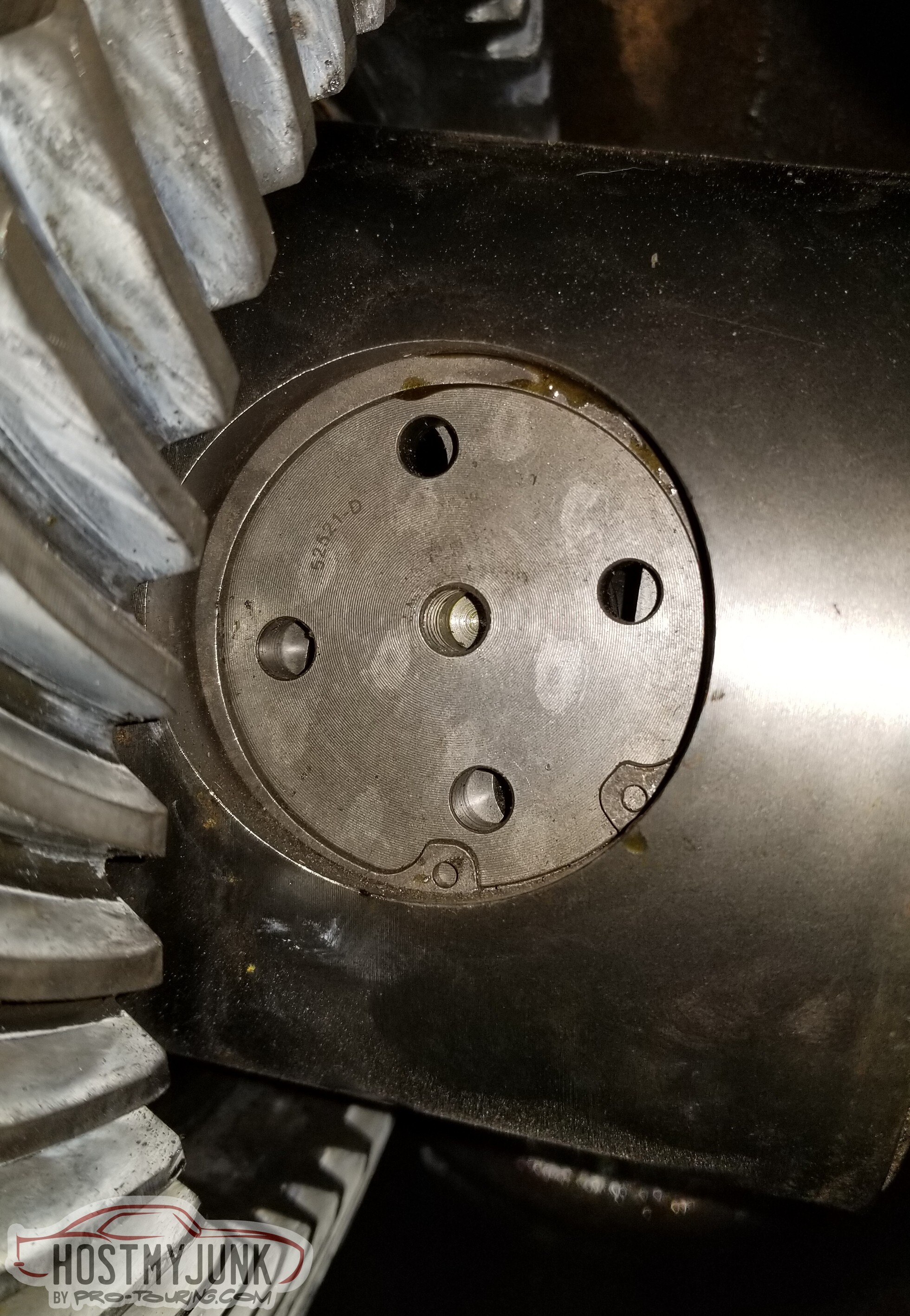
"Pinion depth settings are marked on the face of the pinion"
I can't read what it says. It *might* be a serial number of 150 and a depth of 2.792? It looks like something-92, at least.
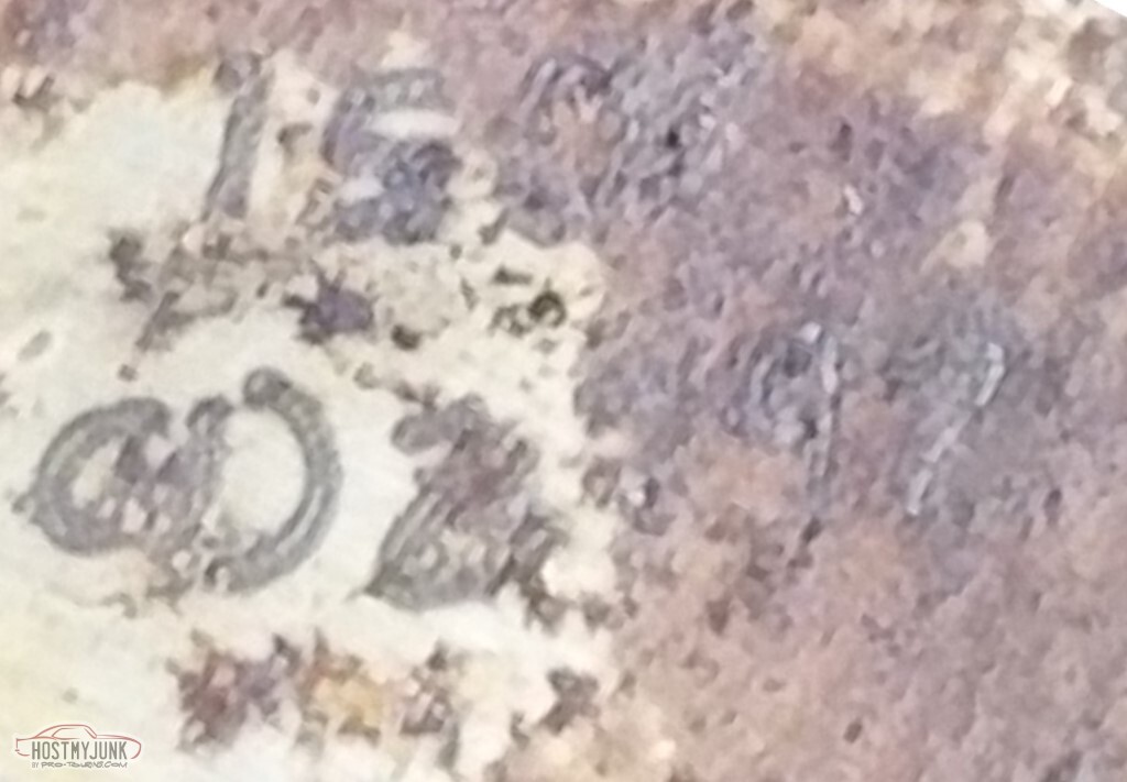
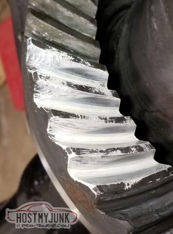
Alternate pic, seems a little less legible
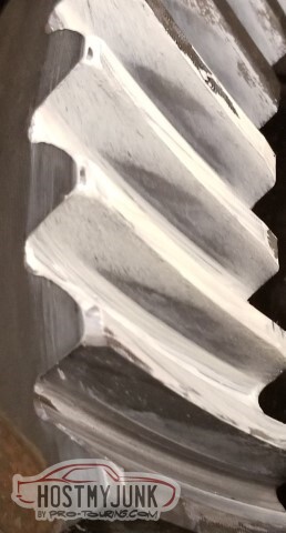
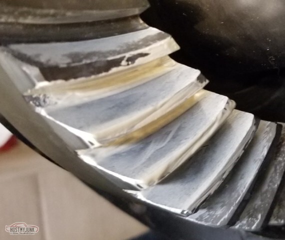
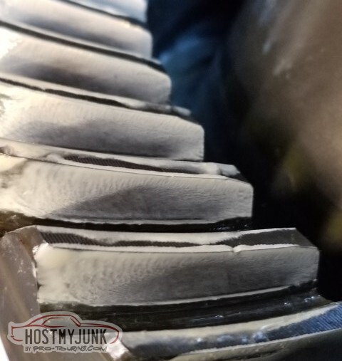
Also from the instructions:
"Backlash settings are marked on the outside diameter face of the ring gear", as well as serial. This is maybe also serial 150 and backlash of .009?
Richmond support just said that 12 bolt pinion depth is 2.795, period.
Part number and such.
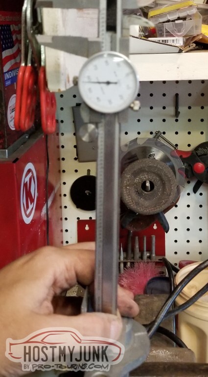
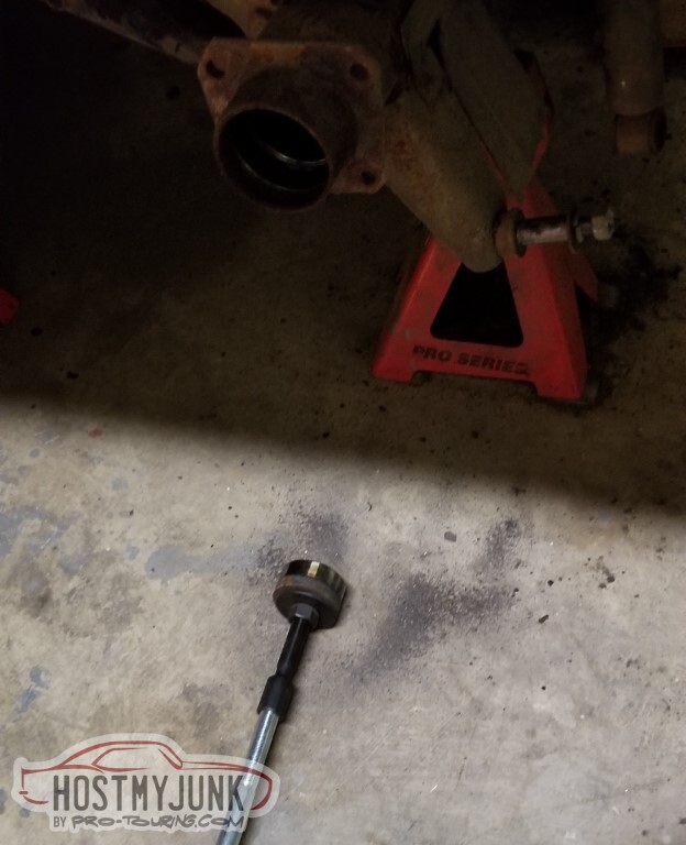
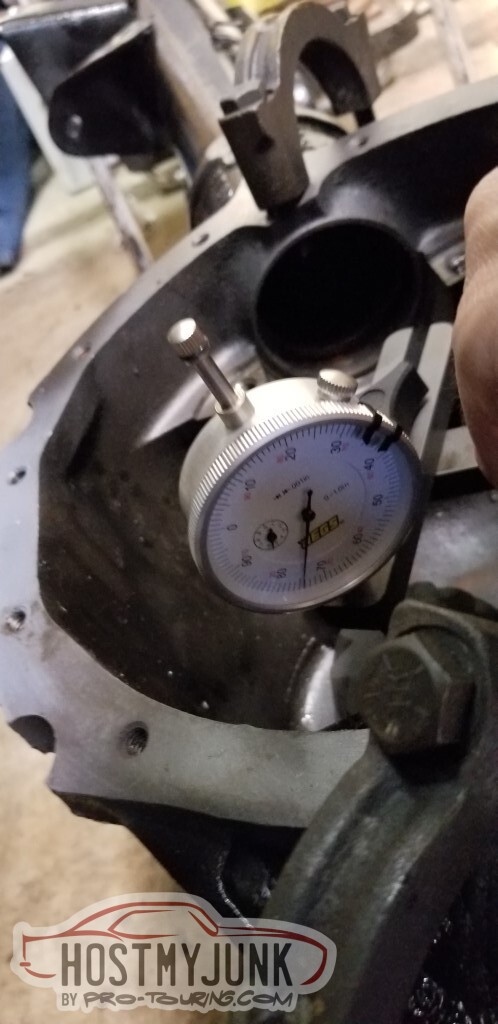
I tried to use this pinion depth tool. It did not go well.
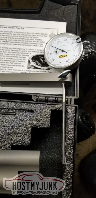
Step 2 in the Jegs instructions: "Zero the dial indicator using the supplied checking block and appropriate extension.. slide into collet until dial reads zero, then tighten."
The handy chart on the back of the instructions says 12 bolts are 4.670" (this was before I got the response from the Richmond folk), so the 4.3" extension seems appropriate. Figured I'd try it to see what the current shim did.
The 4.3" extension does not bottom out in the checking block so I don't know what this is supposed to do.
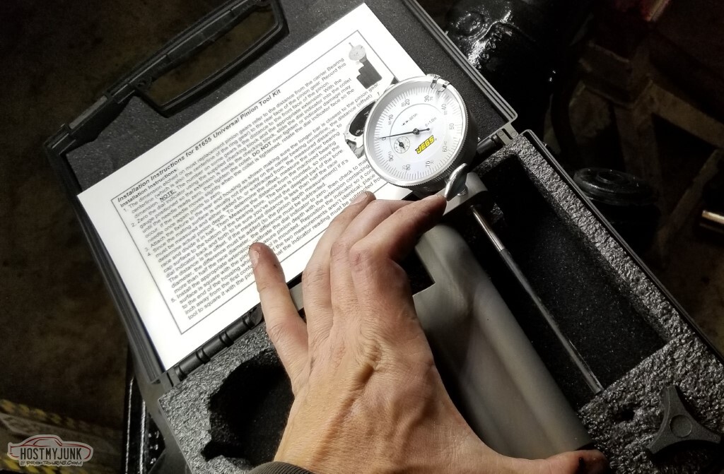
Instructions give the setup to be used
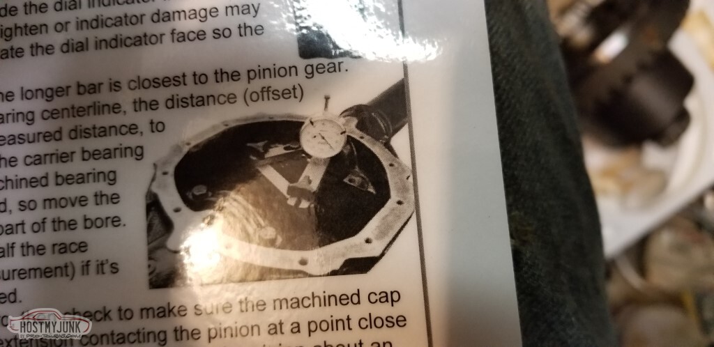
This is not what it suggested and I don't understand it.
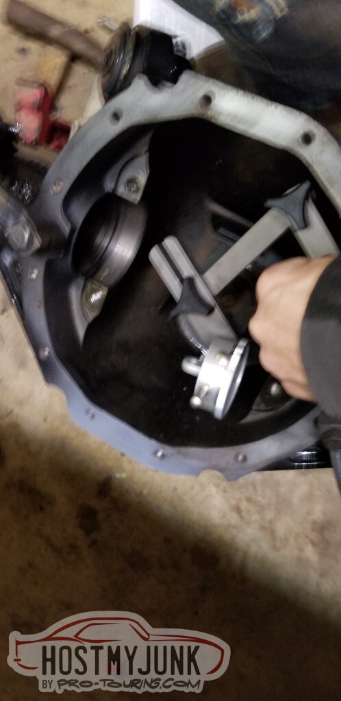
I don't know what to do with this reading. Probably nothing since it's not zeroed and I don't know how to use it.
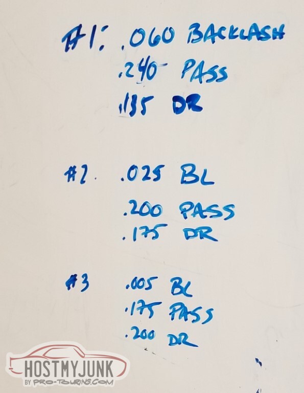
Decided the numbers don't matter, it'll be the pattern that really determines how I'm doing.
Having a whiteboard in the garage is helpful for notes.I can only get about .375 worth of shims in here, rather than the .475 the old carrier had, which concerns me a bit.
Shim kit that came with the rebuild kit had four .100, a couple of .025 and .035 shims, and a bunch of .010.
I was able to try .200/.175 and it's close (.005 is a bit tight) but I think .195/.180 is the right answer, but I don't have enough less-than-.100 shims to do it. Additional shim pack ordered and should arrive tomorrow.
I did try putting the carrier bearings through the press again to see if they could seat any further; they didn't.
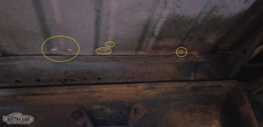
While I wait on shims, may as well clean up the underside some. Circled are holes in the weld I did from the top. I'm not going to try to patch the crossmember.
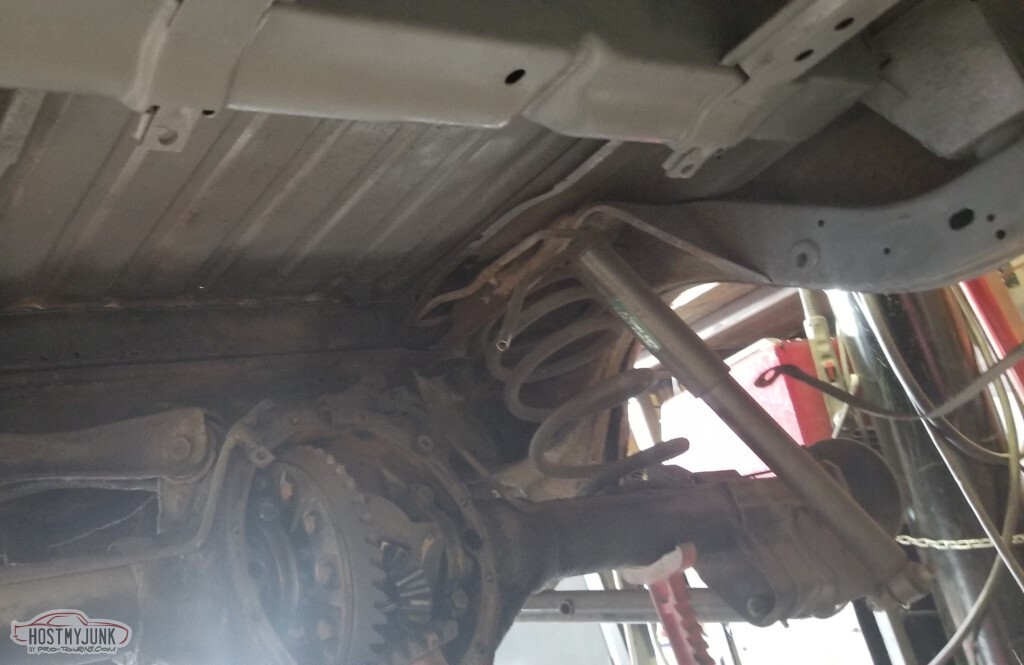
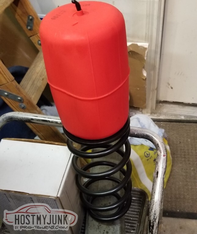
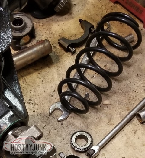
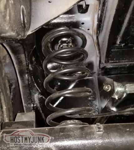
I had planned to run Air-Ride helper bags inside the springs.
Yeah, I don't think that's going to work. The circle-track springs are smaller (4.25" I.D.) than the stock springs (5.75" I.D.). I'll probably look into different bags, I think the helpers will be needed and I don't want to do air shocks.
I've pulled the rest of the parts I'll need for this out - the calipers and brackets, the new yoke, springs, adjustable UCAs. Still need to figure out shocks and brake lines.
I dug through the bucket of parts that came from the initial axle teardown. I'm missing one C-clip. How do you lose a single C-clip? Ordered that too.
-
05-15-2021 #68
-ɹoʇɐɹǝpoW-
- Join Date
- Jul 2002
- Location
- Mesquite, TX
- Posts
- 4,901
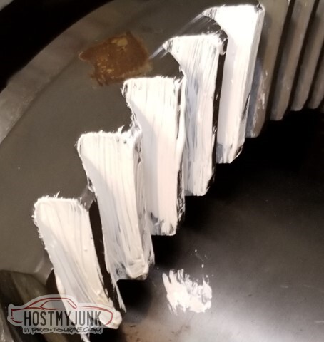
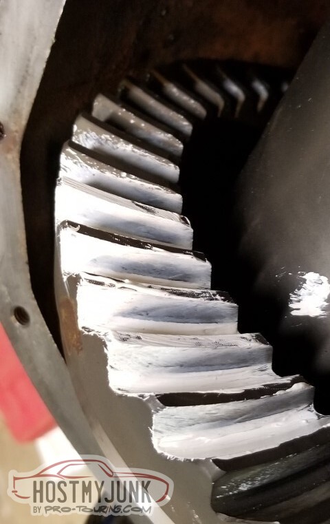
I'll spare y'all - and myself - the trouble of reading (and writing) a bunch of commentary on the gear pattern marking compound and what it shows.
Suffice it to say, .195/.180 was the answer. Backlash is the .008 suggested.
 a
a
 b
b
 c
c
 d
d
 e
e
 f
f
 g
g
 h
h
 i
i
 j
j
 k
k
 l
l
 m
m
 n
n
 o
o
 p
p
With the new shim kit and the appropriate shims installed, I still have almost an inch of shims (and that's not even counting the two original shims I pulled out!)
So a learning thing - if you use a 1.5" pipe to press the pinion bearing on... make sure you are not also pressing the pipe on! I had to use the bearing splitter to press the pipe back off.. may have been harder to do than pressing the bearing. All good though, no scuffing evident (and it wasn't on a wear surface anyway)
New rear spring. More on this later.
So with the pinion in place (and front bearing, and crush sleeve, and pinion seal), next step is to snug the pinion nut on to get the bearings to their races.
It won't get that far. It won't go any further than about .040 shy of putting the front bearing on its race (measured by fore-aft movement)
Stalls with about two threads showing.
What's going on? Am I out of thread (is the washer too thick? Too thin? Threads boogered?)
Washer .235, respectable.
Maybe the impact wrench isn't up to the task.
Off to Lowe's, bought the 750 lb-ft version.
No difference.
Returned that, bought the *1000* lb-ft impact.
That worked.
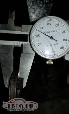
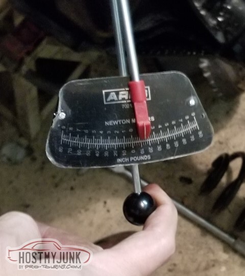
First try, rotating torque right at 15 lbs. Good enough!
I put some paint on the undercarriage where the axle's going to be (conveniently, the last couple of days have been warm enough to shoot paint)
Woo! Time to put this thing in.
Bolts aren't even all the way through, just enough to hold it in place. Still needed to install the axle bearings and seals (also, the Jegs/Summit rear axle rebuild kit didn't come with axle bearings and seals, which was a surprise)
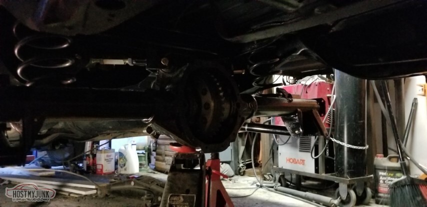
With the new springs, it seems like it's going to ride VERY low (which in general I'm okay with)

<tr><td>This is with the axle jacked up until it started to carry some of the
weight.
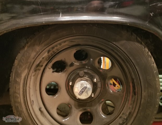
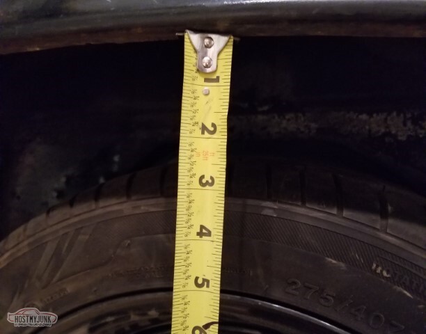
Measured from the wheelwell edge to the center cap: about ten inches (sorry, camera got in a wierd mode amd ate the important part of the image)
To contrast, if I put the old stock springs back in, that's about 14 inches to the cap -- a four inch drop.

With the stock springs.
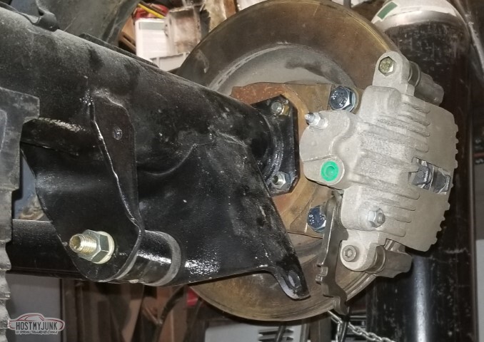
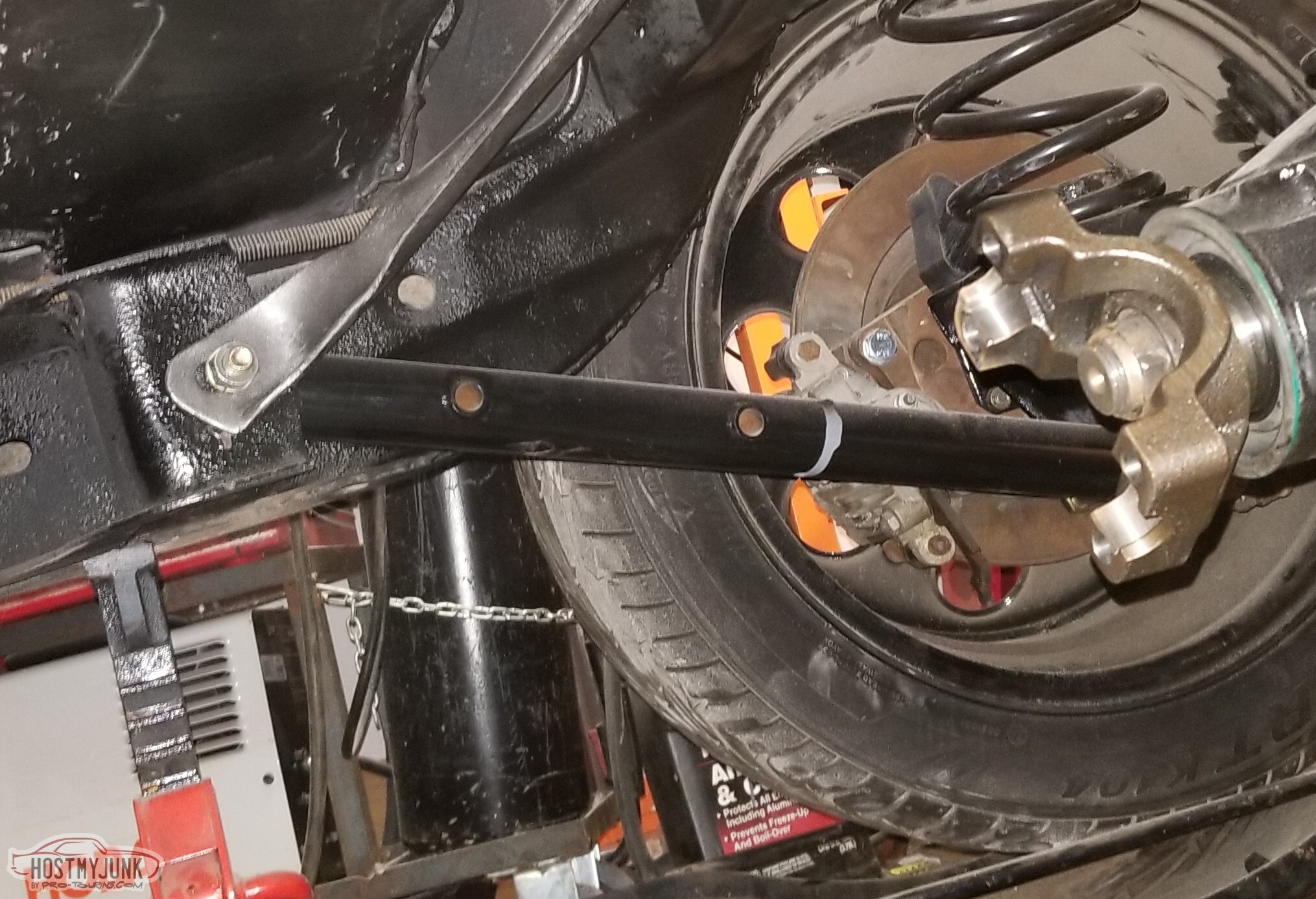
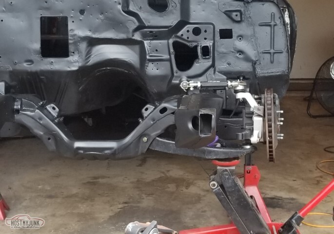
Brake bracket test fit. Forward and down seems incorrect.
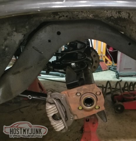
Also the brake rotor wouldn't fit over the axle center flange.
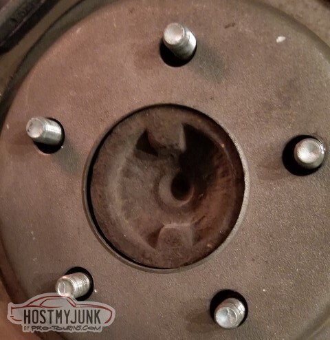
Tried both of the rotors I had. Oddly - not pictured - it fit over the flange on the pass side just fine.
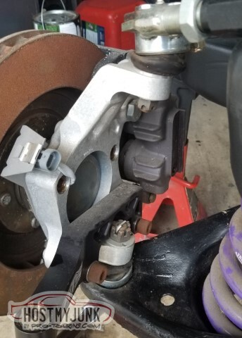
Moved the caliper to the back by swapping sides. This looks more visually appealling to me, although I'd have thought it'd be higher on the rotor (maybe about 2 o'clock instead of the 4 it is)

Can see the caliper through the wheel.

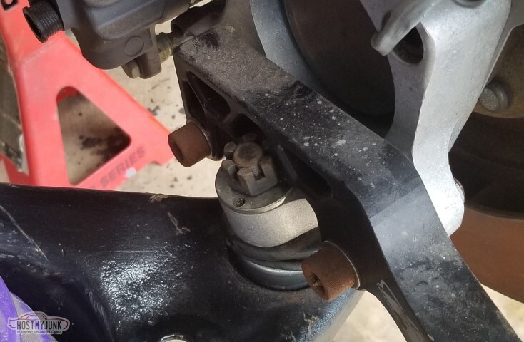
An issue though: The parking brake lever is going to bounce off the post the shock mounts to.
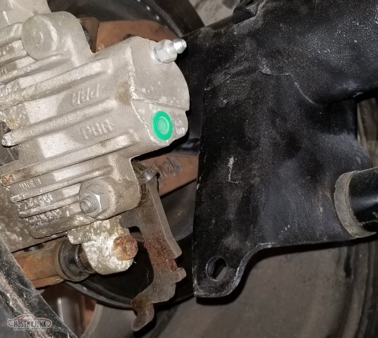
(alternate view)
Looks like the caliper will have to be on the front end after all. Need to research and see if anyone else is putting these calipers on an A-body.
The AC box was "done", for certain values of "done". When I put it together to prepare to start cleaning it up though, I found that on the bottom, the trailing edge wasn't flush on both halves - one side was offset by about an eighth to a quarter of an inch. So - a pie cut, and start fiberglassing that too.
Moved on to the poly body bushings. They don't photograph well, so you get this image of the 50 year old stock bushings instead.
I've got five done, of - what - 16?

Back to the springs. I have strong concerns here. The springs are not well held in place and I suspect will fall out if the suspension ever enters droop.
My notes indicate that these springs (150lb) were ordered after consultation with Dennis on the pro-touring board (... back in 2005) but I have no context for the discussion and can't find it in forum nor PMs (nor archived emails).
I tried to send Dennis a PM but he's not logged on in the past 5 years and not posted in the last decade.
Either the answer will be spring adjusters like in the front (and *something* to keep the springs from falling out) or I'll be getting stock-ish springs instead.
Ain't got to decide today, which is good, since I'm not.
The nice part is that I'm essentially done with the diff (reckon I'd better knock on wood after that statement). Still need to move the calipers again, and run the brake lines, but then I should be able to put in the C-clips and close it up.
-
05-15-2021 #69
-ɹoʇɐɹǝpoW-
- Join Date
- Jul 2002
- Location
- Mesquite, TX
- Posts
- 4,901
The decision is made: Let's buy the correct springs (and some shocks, and some sway bar). Ordered from my FLAPS (which in this case was Pep Boys' "Speed Shop"). Better pull the shock mounts out.
Put the C-Clips in, and went ahead and installed the spacer-thing for the Tru-Trac (equivalent to the pin in a normal diff).
Was a little bit of a pain - my snap ring pliers don't open quite enough to get a good grip, instead I ended up helping it in with a screwdriver. Not sure if I'll be able to get it back out.
So with the wrong springs, this is how it sits.

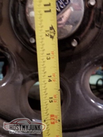
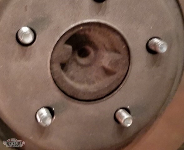
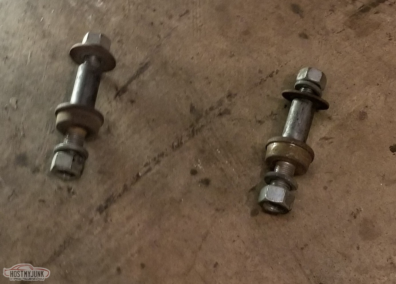
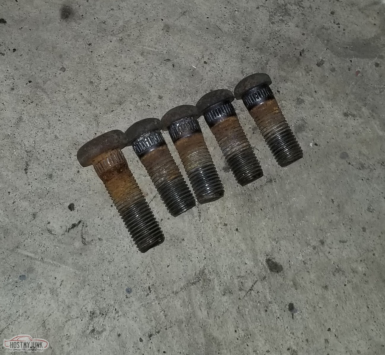
So when I put the wheel studs in, I noticed that the passenger side studs were not as long as the driver's side (I don't think I'm surprised, I had to replace the studs on the driver's side in maybe 2002? Lugnuts had come loose and the wheel had beaten up the studs too badly to keep.
Driver's side: 1.1154 protruding past the flange.
Pass side: .895.
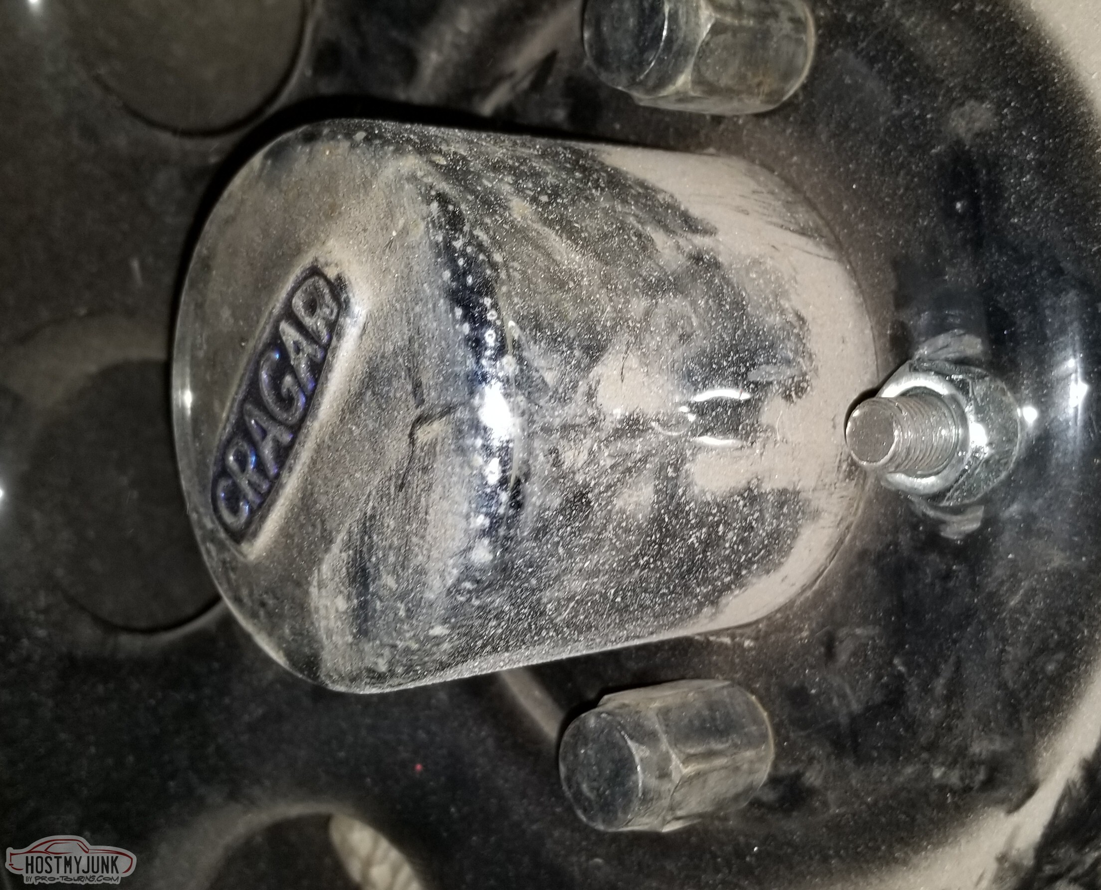
It was obvious with the rotor and wheel on, the stud didn't extend to the face of the open lug nut.
(and good luck reading these pics)


I bought new studs.
I actually went with the rear studs for a 69 Camaro with 4 wheel disc; where the El Camino stud has 1.09" of threads, the Camaro stud has 1.359" of threads.
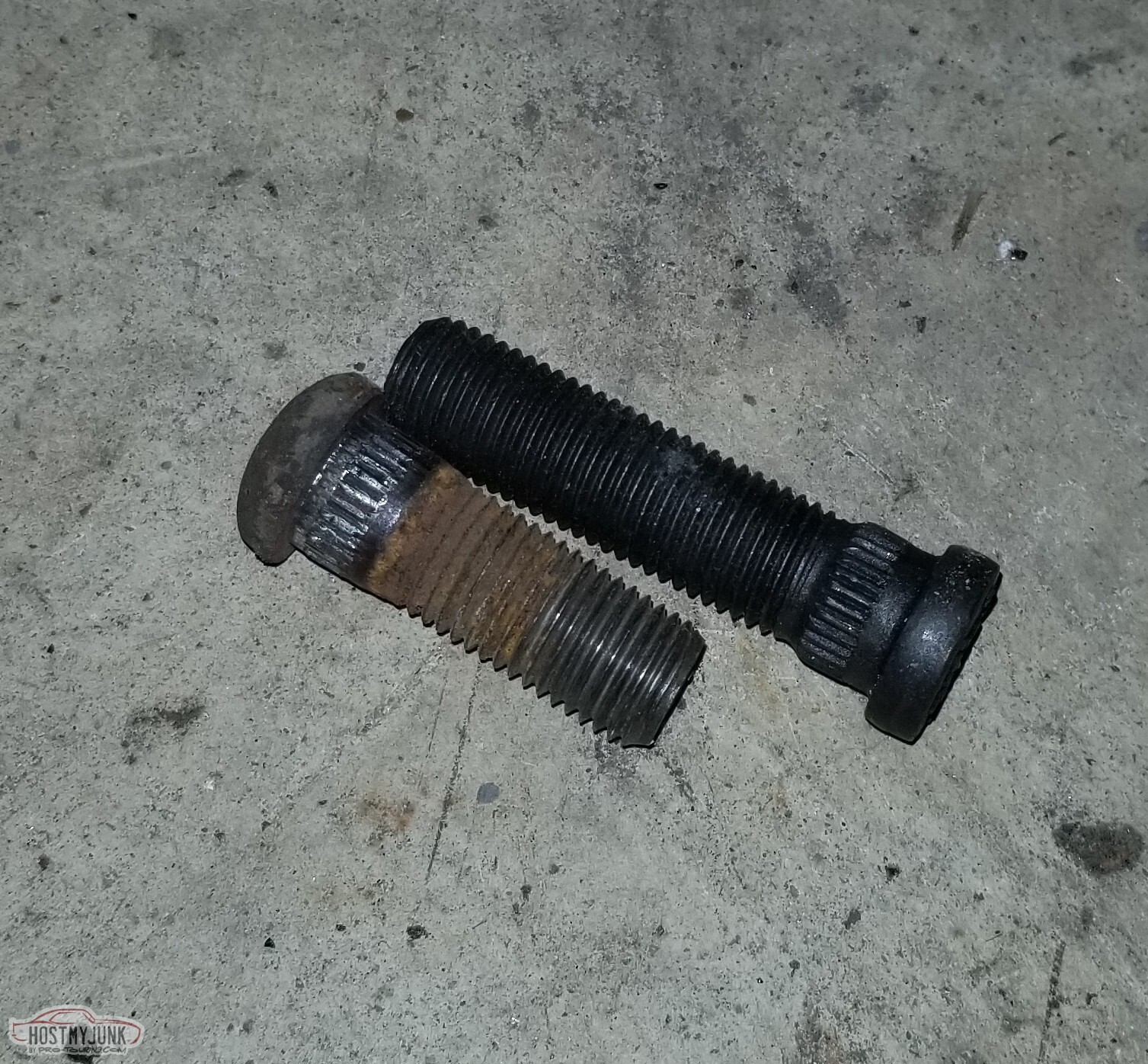
And it turns out, my studs weren't even consistent.
Unfortunately, one of the studs didn't seat. When I tried to pull it the rest of the way on with the wheel stud tool thing, the nut seized onto the shaft.
Helpful hint: Plasma Cutter is probably not the correct tool to remove the nut (but I didn't want to damage the stud installer)

Now we've got plenty of threads clearing the open lug nut, and the closed lugs will still work.
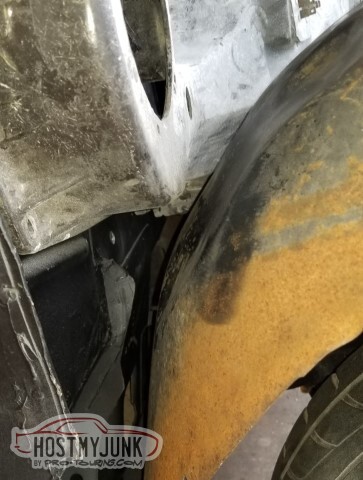
On to body mounts. You can't really tell from the pic - and I couldn't get a better one to demonstrate - but the body is slightly too far forward for the mount to line up (maybe that's to be expected from the wreck in
1991?)

Used a ratchet-strap to pull the body back a little.

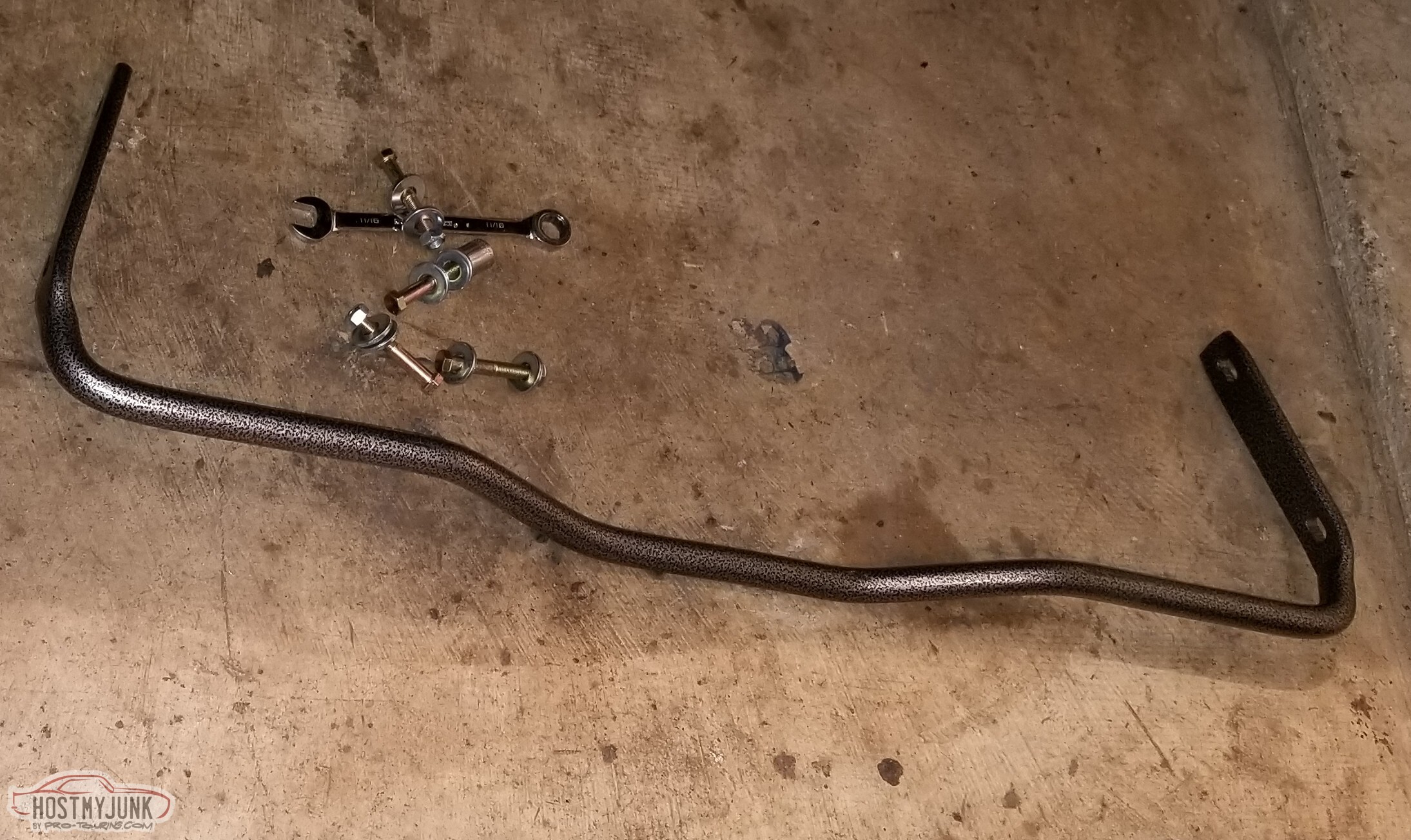
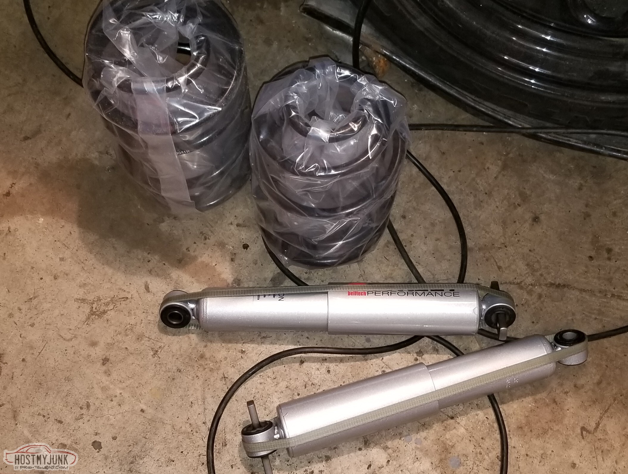
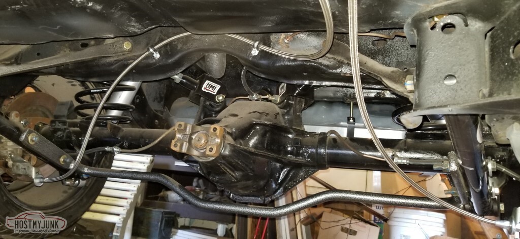
Parts came in! Summit branded (secretly a Hellwig) 1" rear sway bar
Also UMI Performance 4051R lowering springs (2" drop) and Belltech 2209IH lowering shocks.
So before I put the axle in the car, I'd looked at pictures of how the LCAs go, specifically to make sure I got the sway-bar holes on the right end.
And then I put them in backwards anyway.
Had to pull them out and correct.
With the LCAs oriented correctly, and the shocks mounted on the studs. I had to grind the sway bar hole-things on the BMR lowers down a little (maybe .100" on each side?), otherwise I couldn't get the swaybar to line
up. I don't *think* I ground too much off, there certainly isn't any play.
I also used different (longer) bolts than the ones supplied and added lockwashers.
Mounted the shocks to the frame. Was adjusting the UCAs when the wrench slipped and slammed into my cheekbone. Done for the night at that point. Came back once the swelling went down, installed the
rear cover.

The rear brake hose bracket that I'd been looking for wasn't in the drawer marked "brackets" nor in a coffee can pending sorting because it hadn't actually been disassembled - it was still in the bed of the truck with the brake lines attached.
Sandblasted and painted.

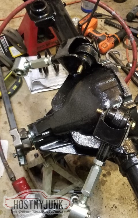
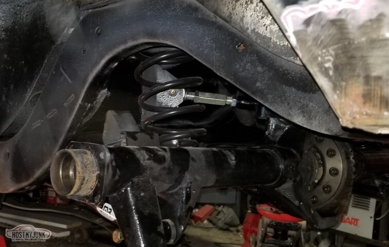
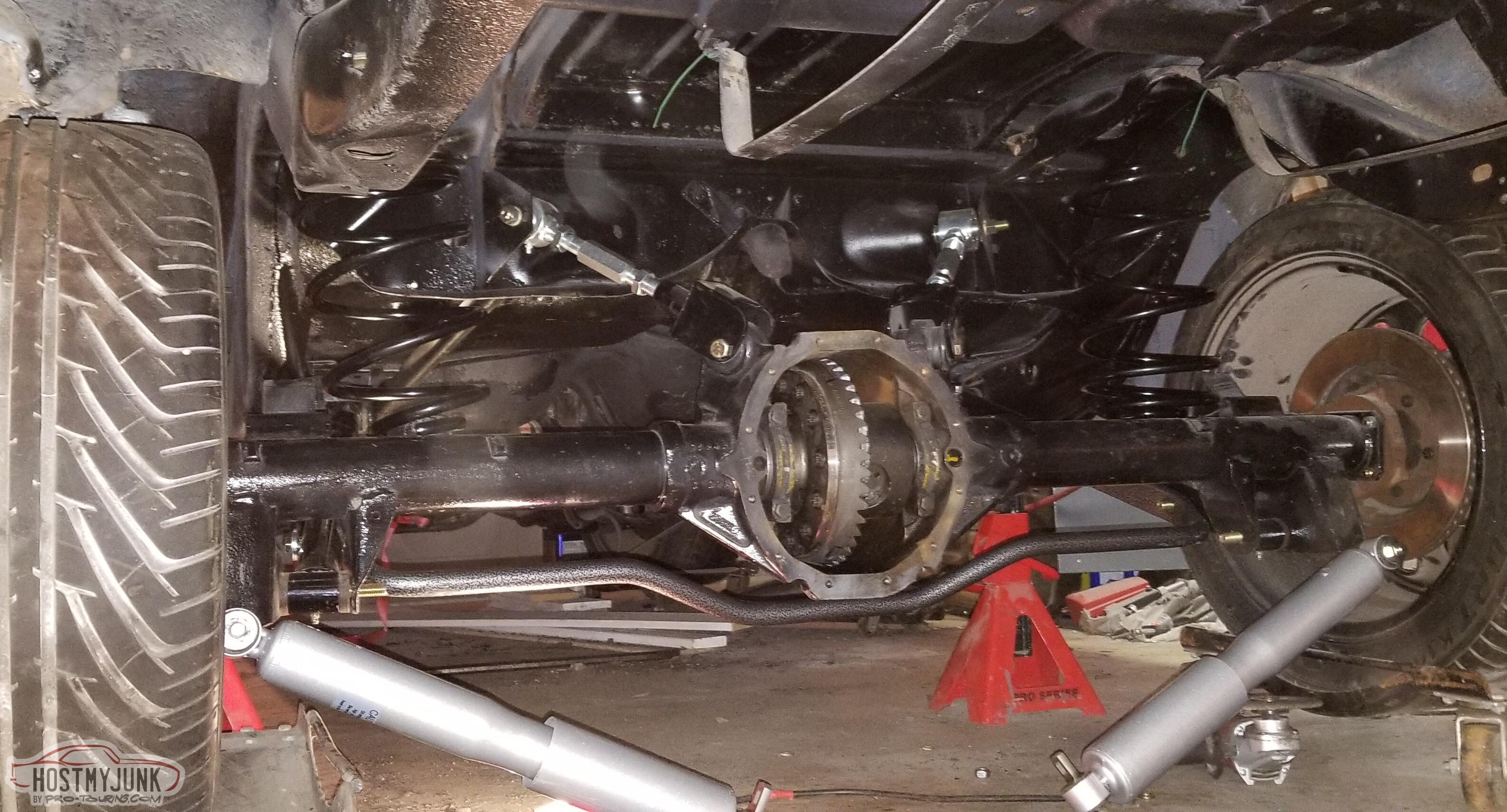
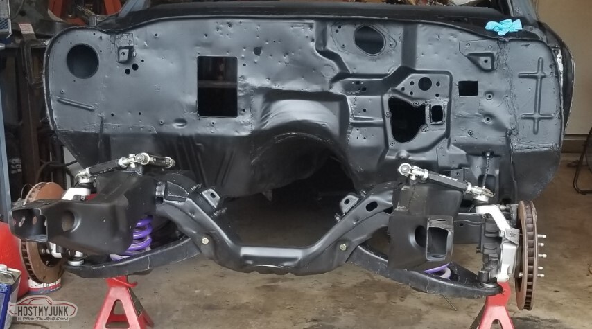
With everything bolted up - but not torqued and the pinion angle remaining wrong - here's what it looks like.
I don't think the picture really shows what you can see in person - the back is low and the front is high. We knew we were going to have to adjust the front anyway.
Well. Maybe I knew, I told y'all that back in post 46 and you might have forgotten.
So here's the default height in the back now.
Note: The rear suspension is not correctly adjusted. There is some serious bind when I try to bounce the rear end (I'm sure the two uppers are different lengths). Maybe it'll be lower once I fix that.

Helpful note: If you're using a ratchet-strap to move the body around in relation to the frame, the drain cutouts are not good things to hook to.

Got the front mounts lined up, then realized that They Don't Matter -- since they just take a nut, they don't care where they line up.
With these lined up though, everything else was really close.

With everything done except the core support, I found myself with the two 4045 biscuits I'd expect, and a 4041 and a 4042 where I should have had two 4042s.
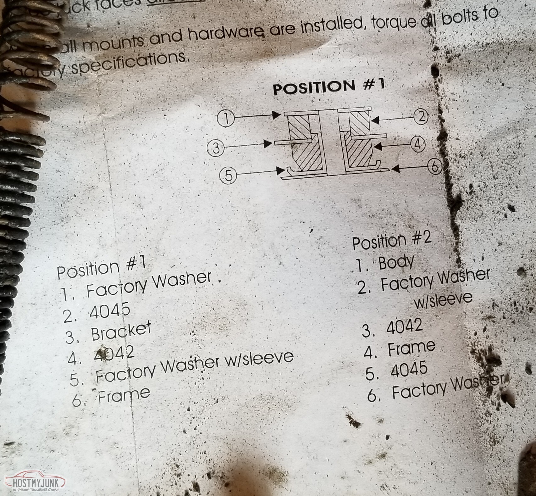
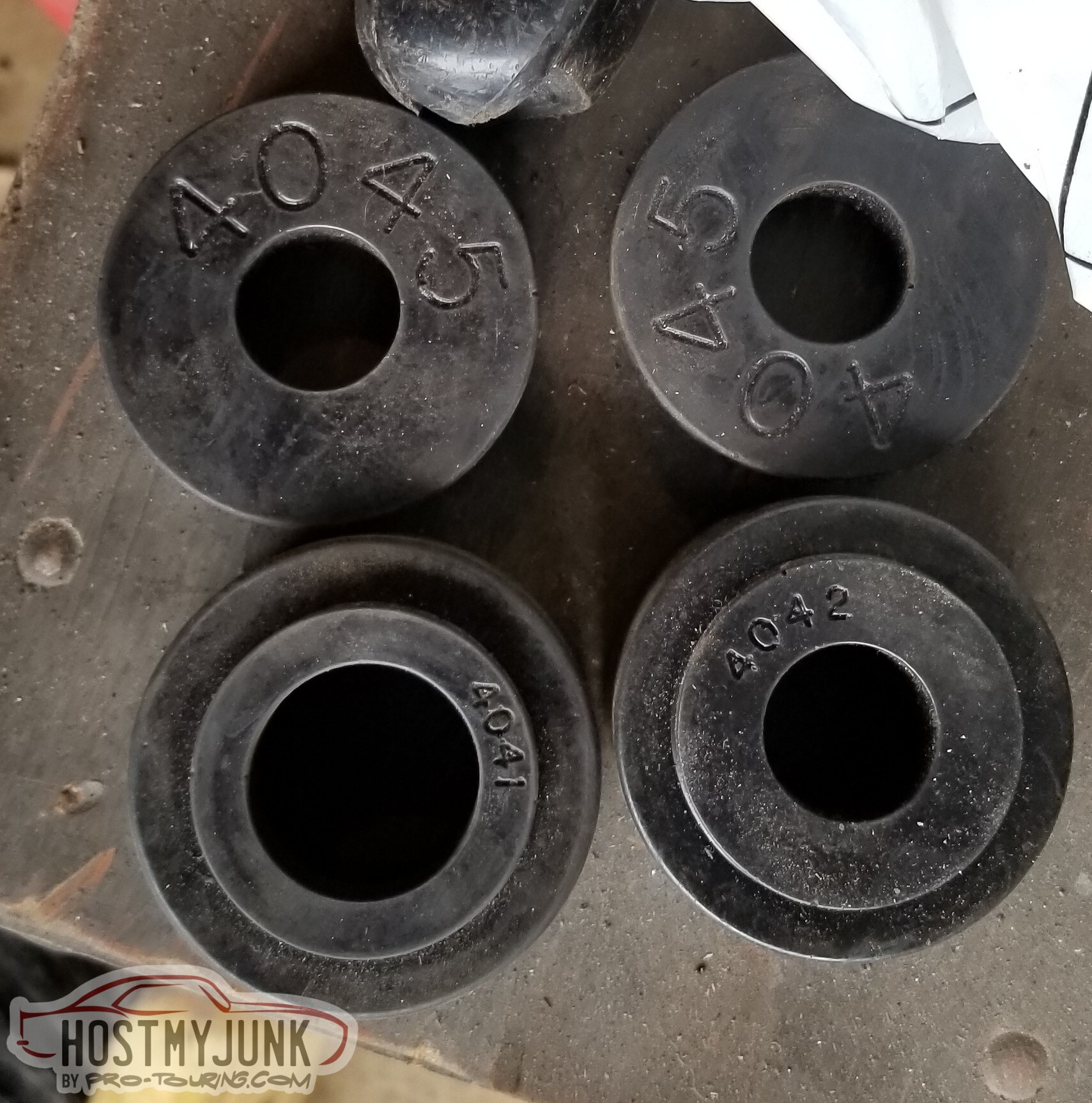
Well, carp. I'd done an inventory of the parts before I started, and I had the right count of everything; I must have used a 4042 where I needed a 4041.
And, in fact, the fifth one I checked I'd done just that.
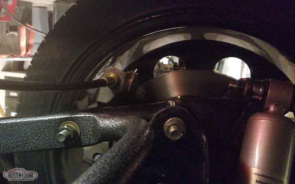
I do have a concern with the brakes again though - I've found a source for the e-brake brackets, but it looks like I don't have much room between the caliper and the LCA. Suppose we'll find out. </td><td>
At this point, the rear suspension is *mostly* done (I'm lacking a fine-thread nut for one of the shock studs, and as mentioned it needs adjustment).. and also I need to run brake lines, but not until I know if I'm going to need to move the calipers again.
The body mounts are "done"; the two rearmost body bolts broke (because of course they did) and the plate over the back of the bed will require an impact screwdriver to remove (and I can't find the bits for mine) and hopefully I can
access the rear mounts from there without cutting the bed up.
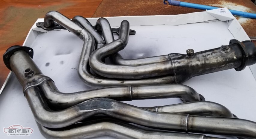
Next up, I suppose, beyond the above, is to cut the headers up (gulp).
-
05-15-2021 #70
-ɹoʇɐɹǝpoW-
- Join Date
- Jul 2002
- Location
- Mesquite, TX
- Posts
- 4,901
I did get the e-brake brackets and apparently didn't take any pictures while I was getting them onto the calipers (an hour for the first one, five minutes for the second).
Bought a stock 94 Camaro ebrake cable just to check routing. It'll be fine.
If the calipers are in their final location, then it's safe to add tabs for the hoses.
(Not pictured: also painted the new tabs and ran the hardline and connected it all up)
Lokar ebrake cable is on its way and that should complete this evolution.
Relevant p-t.com discussions here and here.

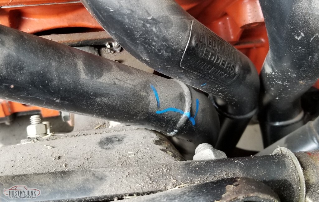
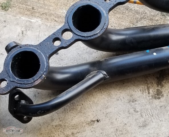
I'm not going to be cutting up the headers. Instead, I hit them with a hammer. I'd been pointed at this video (if the link wanders off, it's the episode of Engine Masters where Freiburger and Dulcich beat up a set of headers on an engine while it's on a dyno to see just how much power is lost - spoiler: damn near none) so I became okay with pounding some dents. Still needs a little more but at least it bolts to the head now.</td></tr>
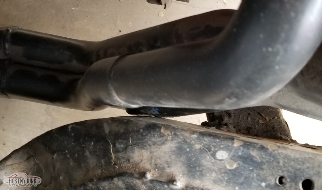
Same answer on the driver's side, but this is fine and doesn't need any more beatings.
Oddly enough, the driver's side I'll have to move the o2 bung as it exits the header right at the frame curve and there's not room for the sensor; pass side won't require the updates.
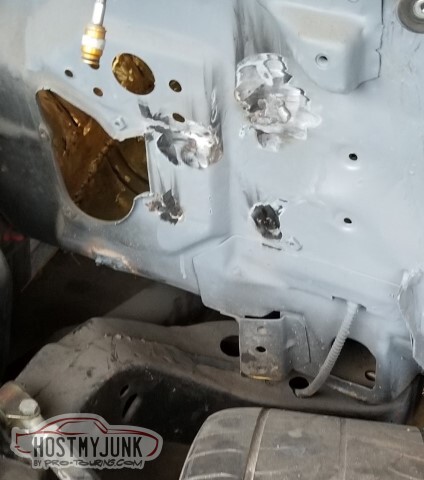
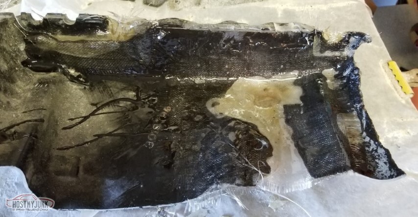
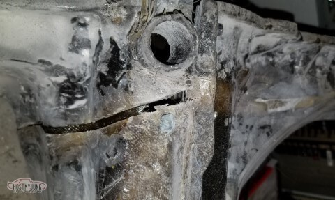
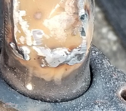
So this is horrible.
Not in a "what kind of novice welder would make those welds" - I'd mentioned back post 65 about my gas flow issues when I did this abomination.
The part I didn't realize at the time was that the flanged portion wasn't supposed to be against the firewall - it's to seal to the hydraulics bracket!
I don't really know how I'm going to handle this yet, beyond cleaning up the welds.

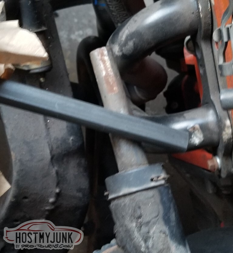
So if you measure a double-d shaft, the dimension across the flats is NOT the actual size - it's the long dimension across the Ds. The Camaro steering column is a 1", compared to the 3/4" shaft laying across it.
I found the keys. They fit, they work.
I mounted the column, temporarily.
Need to alter the panel a little behind the abomination-clutch-hole-thing.

And then I went to Summit!
I'd lost faith in my plan (post #24, from 2008!) for the pickup-pump-filter on the stock tank.
Instead - Tanks makes a full kit with an in-tank pump (with baffling, etc.) and I don't have to clean up my old tank.
Do need to figure out the little bracket that goes on the filler tube (not pictured, maybe next time), new tube doesn't have one.
Getting it from the local Summit beats having to pay shipping.

Got a u-joint that *should* fit the Camaro column.

Also - not pictured - apparently my fuel line for the engine was low quality and I needed to not be using it (p-t discussion here) so I got the equivalent Fragola hose and All Should Be Well.
So really the current status is:- rear end is full of oil (as it should be) and not leaking
- rear calipers are installed and connected
- rear hardline is done (but not the long one connecting to the front)
- swaybar is in
- rear suspension is torqued appropriately
- everything that is a grease fitting in the back has grease in it
- E-brake cables are on order
- I have (almost) everything for the fuel system - need a new gas cap, some ethanol-resistant hose for the vent, and to figure out the filler tab thing.
-
05-15-2021 #71
-ɹoʇɐɹǝpoW-
- Join Date
- Jul 2002
- Location
- Mesquite, TX
- Posts
- 4,901
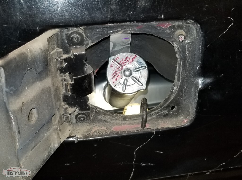
As mentioned - the new filler pipe lacks the tab to secure it.
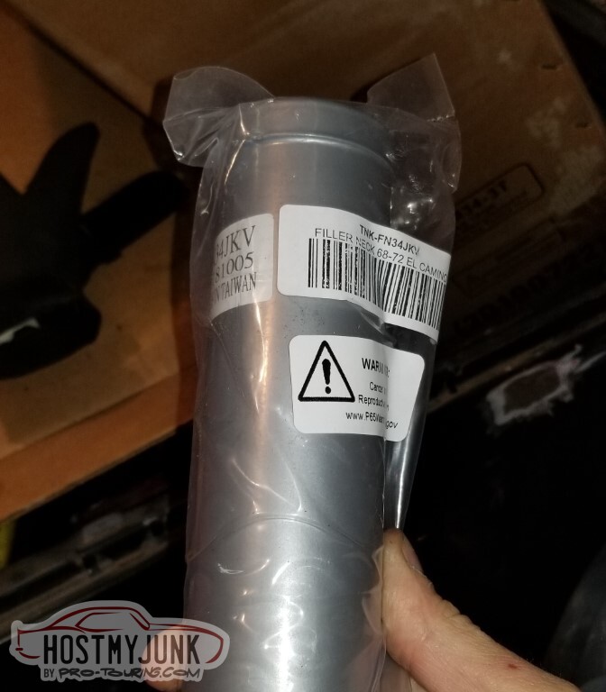
<tr><td>Old one looked like this.</td

Now new one does too.

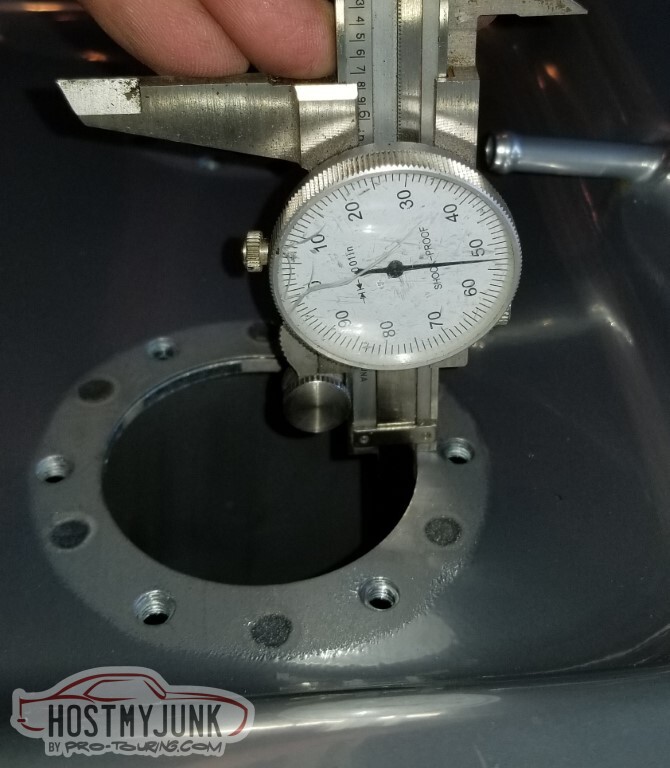
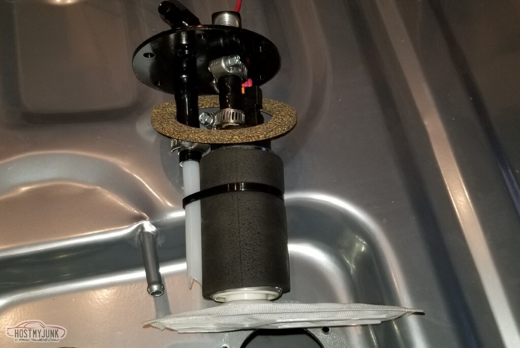
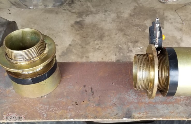
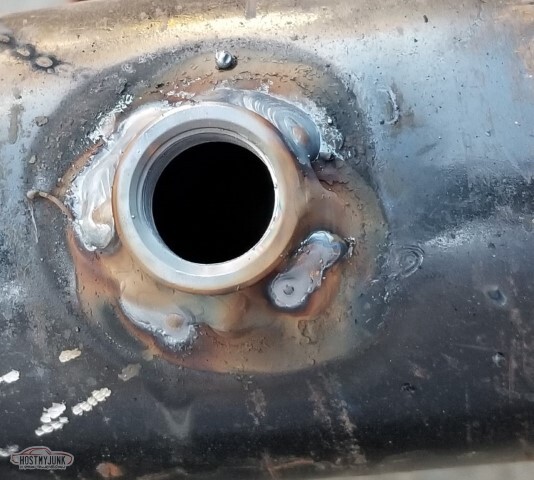
The business end of the new tank. Assembly is required.
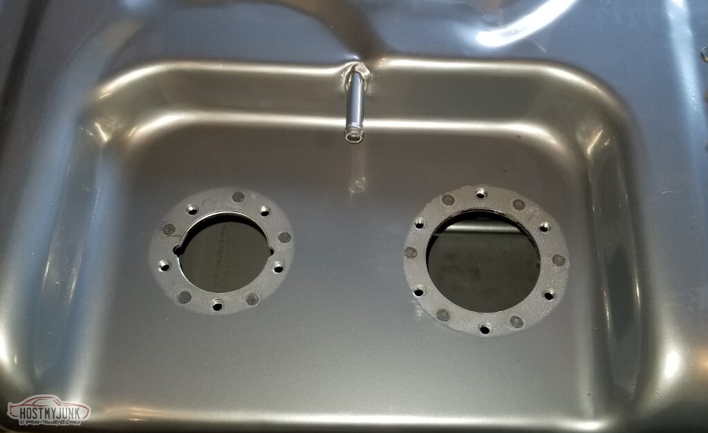
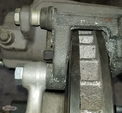
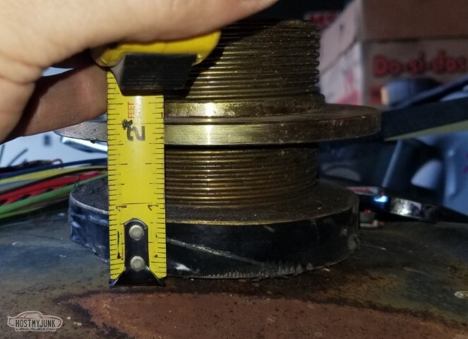
Fuel sender hole is 6.074" or so deep (obvious that the caliper has seen better days)
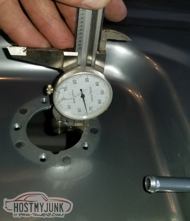
Pump has the baffles so is only 5.752" or so.
Instructions are a little confusing, but okay.
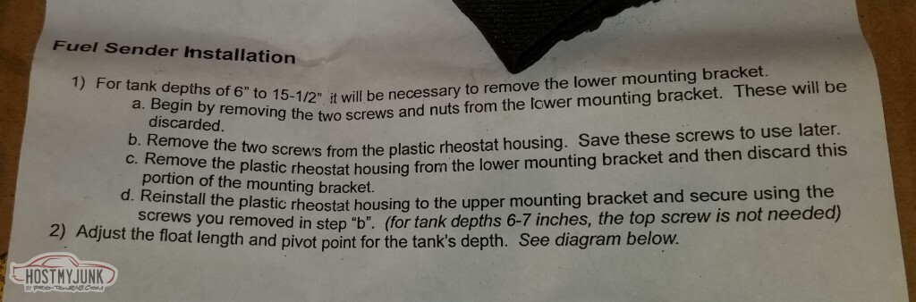
This was less straightforward. In part, it needs to point out that if you leave some excess float arm as it shows there. that *will* catch on the hole and make it really difficult to pull the sender back out and adjust.
Also the float doesn't look like that, it was a ball with a halo (like an old-school goldfish bowl) and it wasn't obvious how to put it.
I put it together and adjusted many times - a couple of times I thought I had it but turning the tank over would not read full (I suspect the ball was getting caught on something).
Final setup was with the ball turned sideways. I read 1.4 ohms "empty", and 90.8 ohms "full" (upside down).
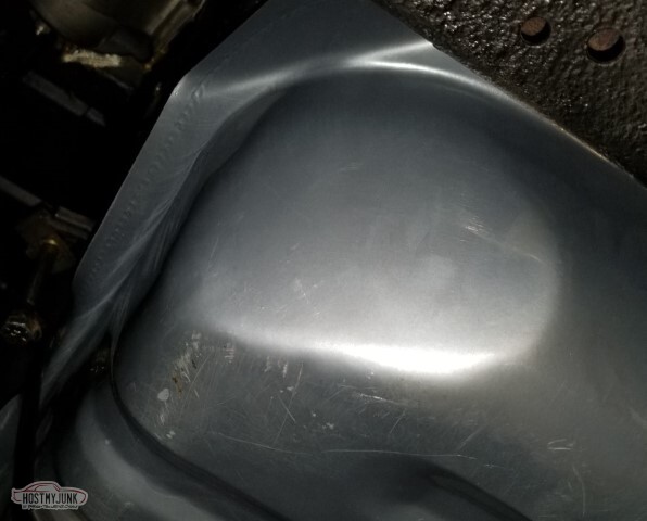
Also during the flipping over repeatedly, the tank slid off the stand and landed on its top, scuffing the paint.

As installed, except without gasket and probably on attempt number seven or so.

Pump was also a pain to assemble, although I didn't take a picture of the instructions.
Big learning here - *install the wiring before you put the pump on the hose if it's this short* - I was sure I was going to break something trying to get the plug into the pump.
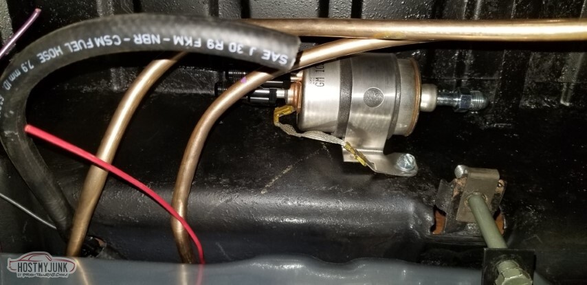
O'Reilly had 18" lengths of J30R9 fuel hose, so I was able to get a start on the vents. In this case there are two and they need to be connected.

The joke was required. Fifty years from now perhaps someone will see this and smirk. Probably not though.
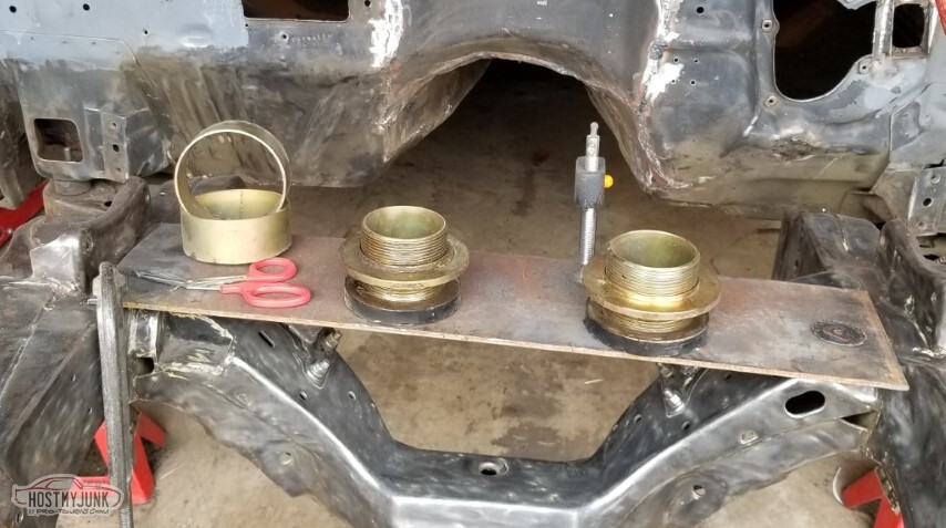
I have a collection of AN fittings. Most of them don't go with the new setup, some I don't think really went with the old one either.
Top row (L to R):
Russell 660655 (AN-6 tube sleeves) - I need these
Earl's 5/16 hose to AN -6 adapter - no longer required
Russell 610165 hose end: Nope
Russell 644123 - 3/8 FI fitting to AN -6 (crap, I bought another one of these on Thursday.. guess I have a return)
Russell 660575 AN-6 tube nuts - need these
Bottom row:
Russell 640853 (Plastic clip version of the 3/8" FI to AN-6, wouldn't be using this regardless, plus I bought it before everyone figured out that they sucked so this is a bad one)
Russell 648060 - Power Steering to AN-6. This I will probably need.
Russell 640930 5/16" male to -6AN. I never needed this, for some reason I decided the filter had female ports on all three.
Corvette Fuel Filter GF822 Yeah, I'll be using this.
Russell 640940 (two of them!) - more male FI fittings I never needed.
and also two Earl's fittings, a M-M 90 degree AN-6 and a F-F 90.
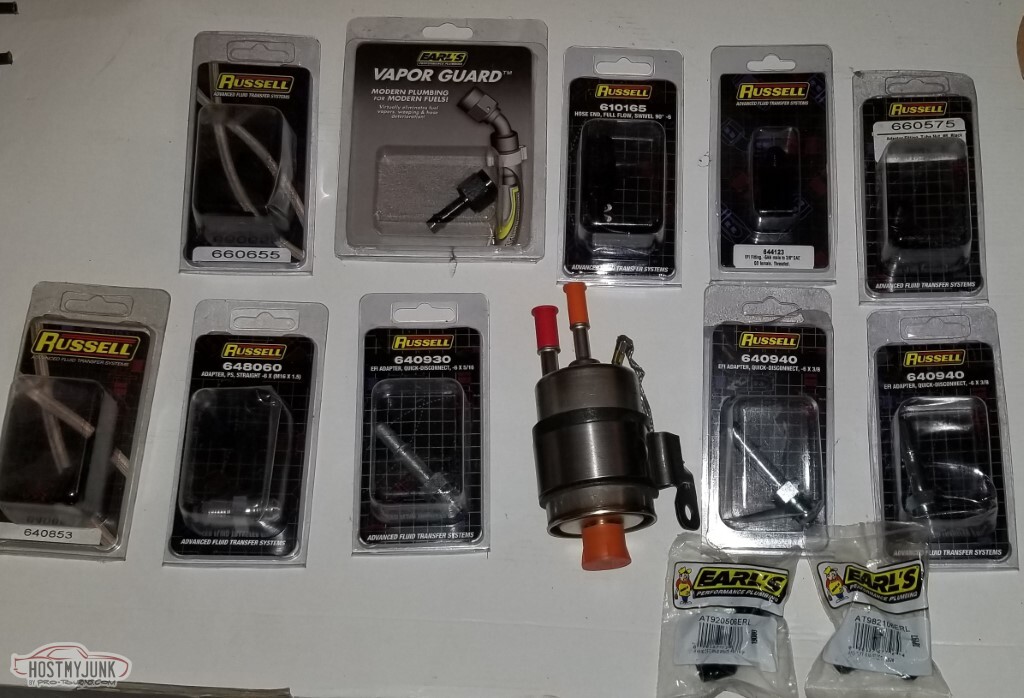
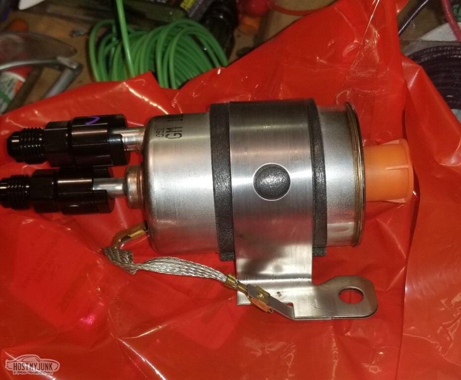
This is the filter/regulator I had (pic was so I could validate that it was correct, it is)
Pic so I could tell where the tank insulation went.

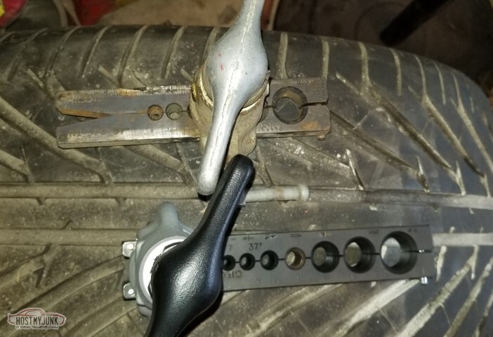
First AN flares.
I think that if you look really hard at the lower line (which is the return), you can see that it is already kinked. If it's not there, it soon will be (foreshadowing!)
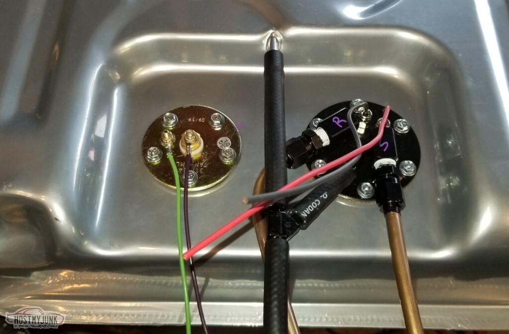
Fittings installed on the FPR.
Added wiring for the sender. Not pictured: I added heatshrink. I've actually got the stuff to create a weatherpak connector for these but hadn't done it here.
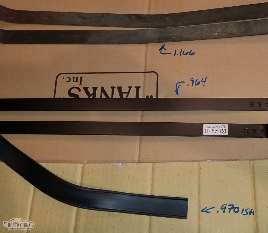
I ran into an issue with the tank strap insulation.
I am relatively sure that my existing straps were the originals. They are 1 3/16"-ish wide.
The (OER) insulation is a channel with lips, and the channel part is only ~.970" wide, which really fits poorly on my existing straps.
The straps that came with my kit are .964" wide, as if they were made for that insulation.
I had to cut the screws to get the old straps out for this pic, so it's obvious which direction I went.
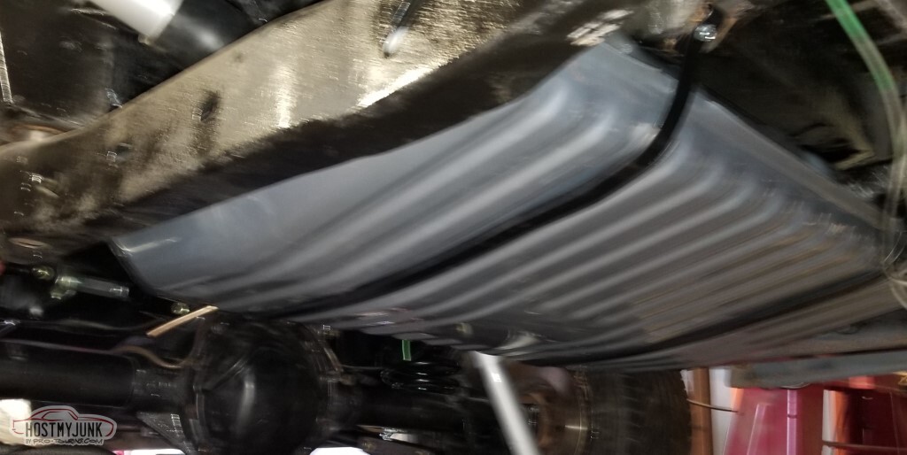
So I put the tank in. It's not permanent; I still need to route the lines, as previously mentioned I kinked one of them so it'll need redone, and I needed to mark where to drill the hole in the bracket here... but this feels like progress.
Also I bought a gas cap.
... and this feels like blurry. The adhesive holding the insulation to the straps says 24h to cure, so this will sit overnight before I pull it down to get it finalized.
Also need to run the vent line, it needs to terminate somewhere higher than the fuel filler which will be a challenge.
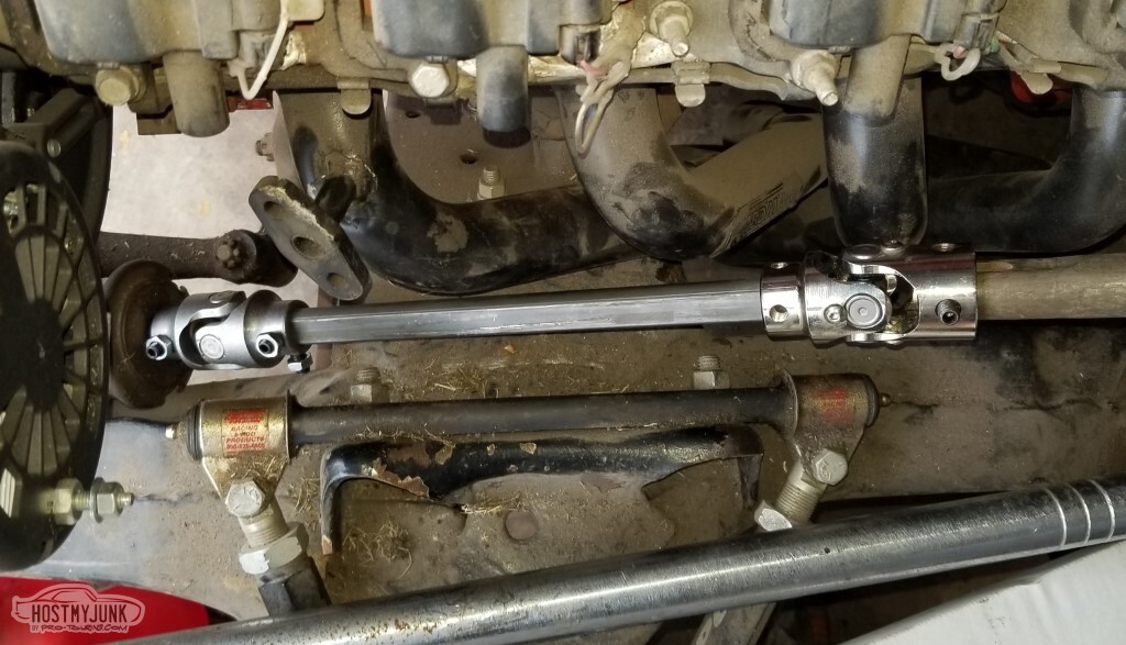
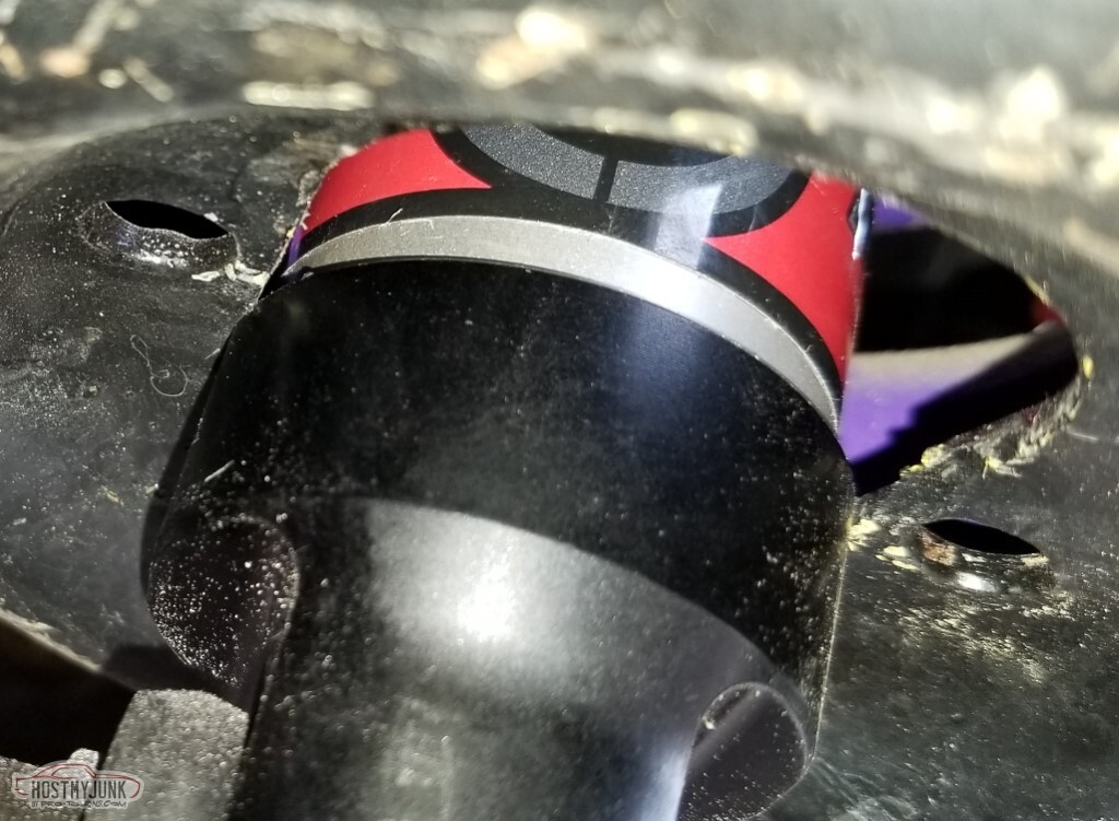
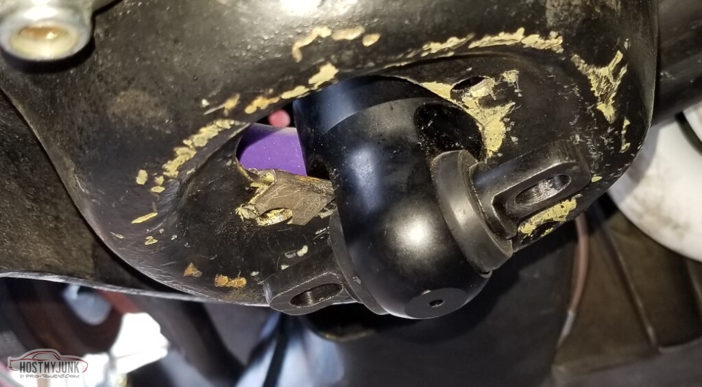
Test fit of the u-joints for the steering. They fit, and there's no issue with header clearance (even if it does look like the top one there is hitting)
I put the Lokar e-brake cable on on one side, and couldn't get it to tighten down on the LT1 bracket.
I think this is the reason - this is with the nylock nut tightened all the way down, and there is probably twice the gap between the nut and the flange that those brackets take. I suspect a lockwasher is my answer.
Also not pictured:- The other end of the Lokar e-brake is threaded 5/16 fine. The existing cable that it needs to attach to is 5/16 coarse. I don't know how to fix that yet.
- Mounted the FPR to the brace in front of the fuel tank. Think that'll work just fine.
- The damaged threads on that pass side wheel stud (maybe I didn't mention that) - I couldn't get a die on there with the handles because of the wheel and the other studs, but I was able to get the die on there by itself and
just tighten/loosen it with a set of vice-grips. Sub-optimal but it worked. - The Lokar tabs for the Aerostar parking brakes seem to work just fine with these, so maybe I can return the Corvette-style ones I bought.
-
05-15-2021 #72
-ɹoʇɐɹǝpoW-
- Join Date
- Jul 2002
- Location
- Mesquite, TX
- Posts
- 4,901
Tanks again!
Yeah, obvious joke is obvious. Also yes, there's a lot of updating going on. Don't get too used to it.
So here it is in all its glory - the tank! Insulation adhesive has dried, so it's time to pull the tank back out, but in the meanwhile: behold!
<tr><td>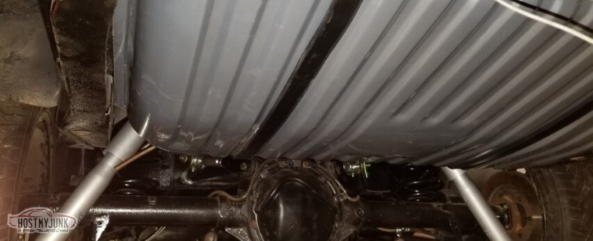
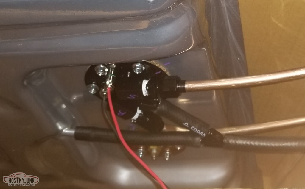
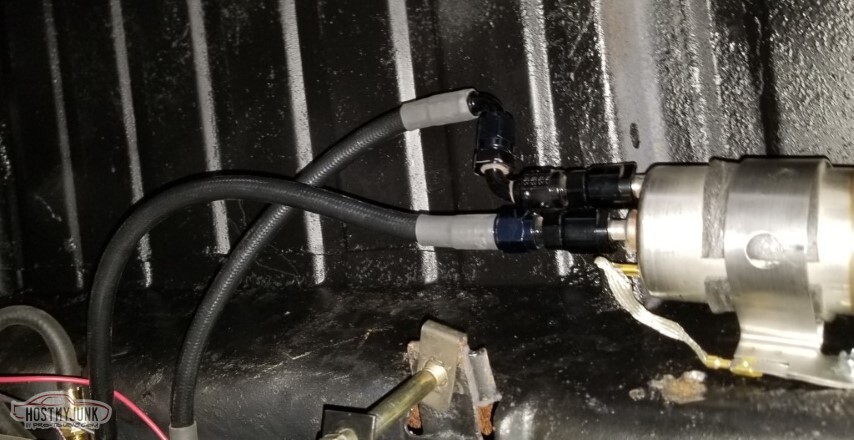
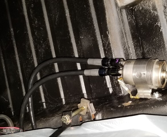
This is roughly where the fuel filter will be mounted (as demonstrated by the fact that it's mounted)
As I mentioned before, the hard lines got kinked. It happened repeatedly.
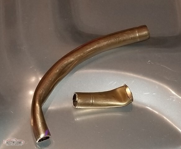
Fixed part of the issue with one of the 90 degree fittings I found in The Pile the other day.

I used connectors. This isn't easy to just step into! I need to replenish some of these, mainly about a half dozen of 12089040 and similar for the seals (and a 12010974/12015797)
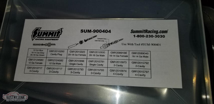
but I got the connector made.

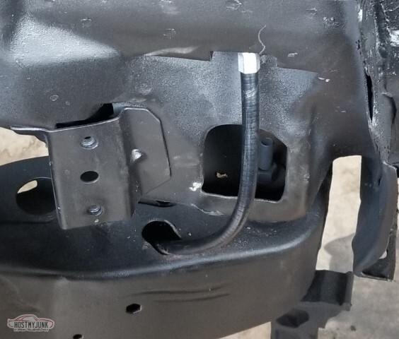
So the Tanks tank requires a vent line, and it says it "must be higher than the filler neck", which is pretty high on an El Camino. There's not anywhere near the tank I can use, and I don't have any 5/16" hardline. What I do have is 1/4" steel line that I'm not going to use elsewhere, and some compression fittings and 5/16" hose barbs. Here the line curves around from the front of the tank to the area behind the filler.
Drilled a hole into the area between the bed wall and the outer wall and ran the tube up there.

Here's what it looks like from the top. Short run of FI fuel hose then the vent above that. Meets all the requirements!

The provided vent with rollover valve is pop-riveted to the inside of the bed, barely visible here.
Need to start in on hooking the hardlines to the FPR.
Also that looks kinked as well.
Also also you can see the other end of the vent tube sticking out (I shortened it a little after this)

Well, they "fit". These are horrible though.

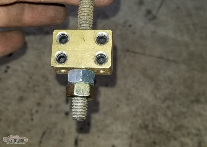
Moving on. Drilled out the threaded hole in the Lokar brake setup and added two nuts.
So the "beat the header with a hammer" plan wasn't working so well... but I have a torch. It's about a 25 year old Bernz-o-matic but it counts. With some heat I started making some progress, right until the point where a leaky valve made the top of my torch into a rocket nozzle (not pictured). Once I extinguished the flaming bottle of death, I'd made it to here.

It's close. Still hits though, barely.

I bought a new torch. It's... insufficient (but it was cheap), but I was able to heat enough to hit it a few more times.

and with those, I now have somewhere between 1/8" and 1/4" clearance (hard to tell in the pic).

With that done, it's time to get ready for the Next Big Deal: cleaning up the welds on the underside and the firewall and painting both. Engine and suspension need to come off for this, and here I've got it almost ready to come out - the mounts are unbolted, the tranny crossmember has been removed.
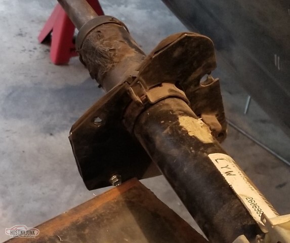
As a bonus - back in post 52, I found that I couldn't slide the driveshaft yoke in the T56. I'd thought that maybe my yoke was damaged (as well as the output splines in the tranny) from trying to force the wrong yoke in. I'd picked up a
proper yoke from an LS-era T56 at a junkyard that also wouldn't slide in.
While I was under there, I wiggled the yoke and it slid all the way forward... so I guess I don't have to pull the tailshaft housing off after all!

I think I'm going to end up replacing the hardlines between the tank and the FPR with flexible so I'll have to at least partially drop the tank for that. Otherwise, we're onto the front end of the car now.
-
05-15-2021 #73
-ɹoʇɐɹǝpoW-
- Join Date
- Jul 2002
- Location
- Mesquite, TX
- Posts
- 4,901
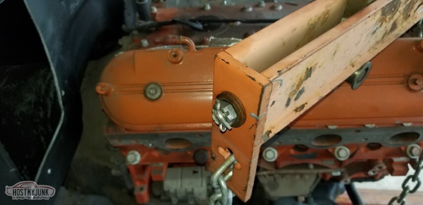
As promised: Engine and tranny come out.
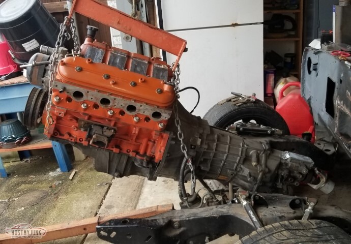
Suspension comes off too.
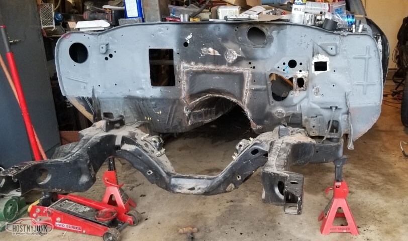
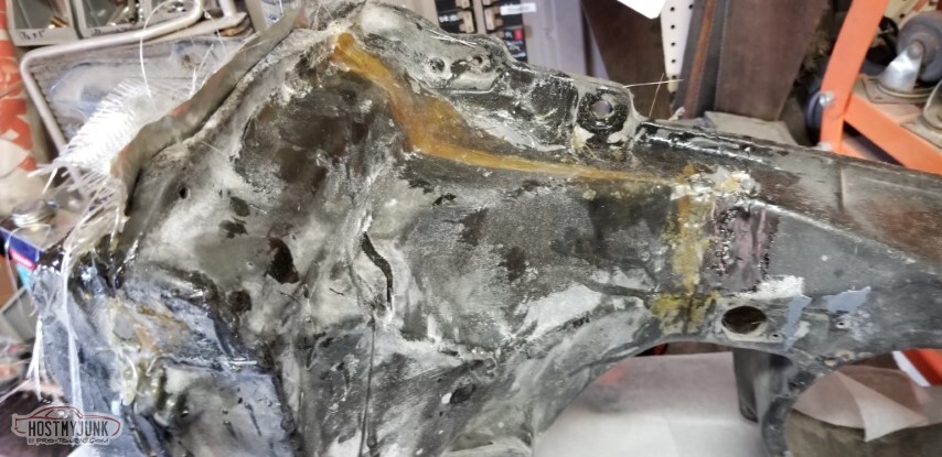
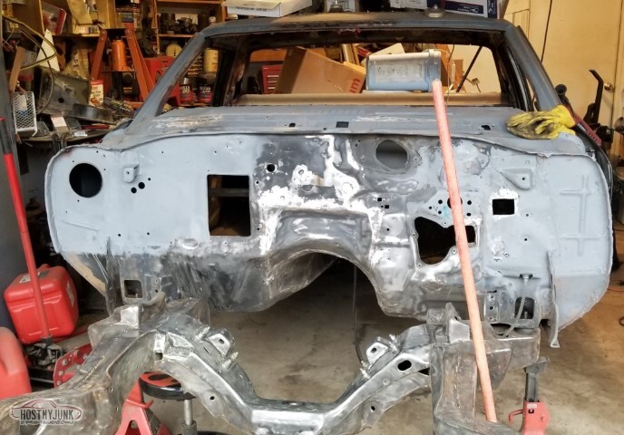
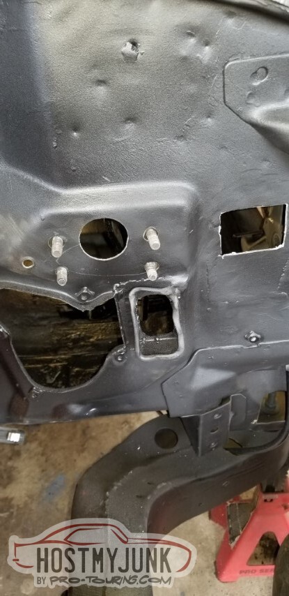
Preliminary grinding of welds
 203220003_tn.jpg"></a></td><td>
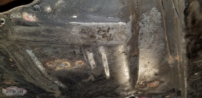
Oddly enough, alternating between a putty knife and an angle grinder with an extremely aggressive wire brush, I found some areas that just had a "protective layer of grime" and with a putty knife revealed pristine metal.
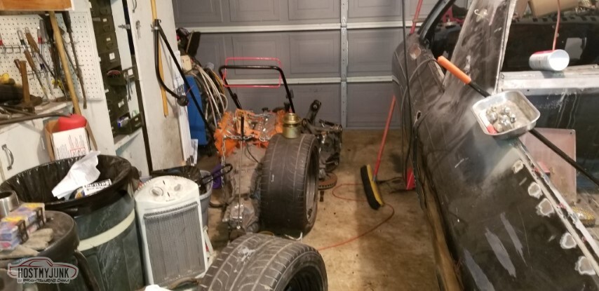
It gets crowded with the front end of the car next to the car. Incentive to get this done.
With some die grinder work, it almost looks like this was done correctly. Almost.
The nice part about an aggressive wire wheel (knotted wire) is that it will show you where the weak metal is. The bad part is that it will find weak metal to show you. This is the drain that was damaged with the comealong. Guess I don't have to straighten it now.
Instead, make a patch.

Similarly - further forward, there's several new holes.
Passenger side was even worse. The pic is from the underside - the metal here is nice; the rusting was from the top.
And again, additional holes in the toe panel area on the pass side.
Corrected. Welding seems to have improved a little.
Same wire brush (pictured, even) cleaning the rust and old paint from the frame.

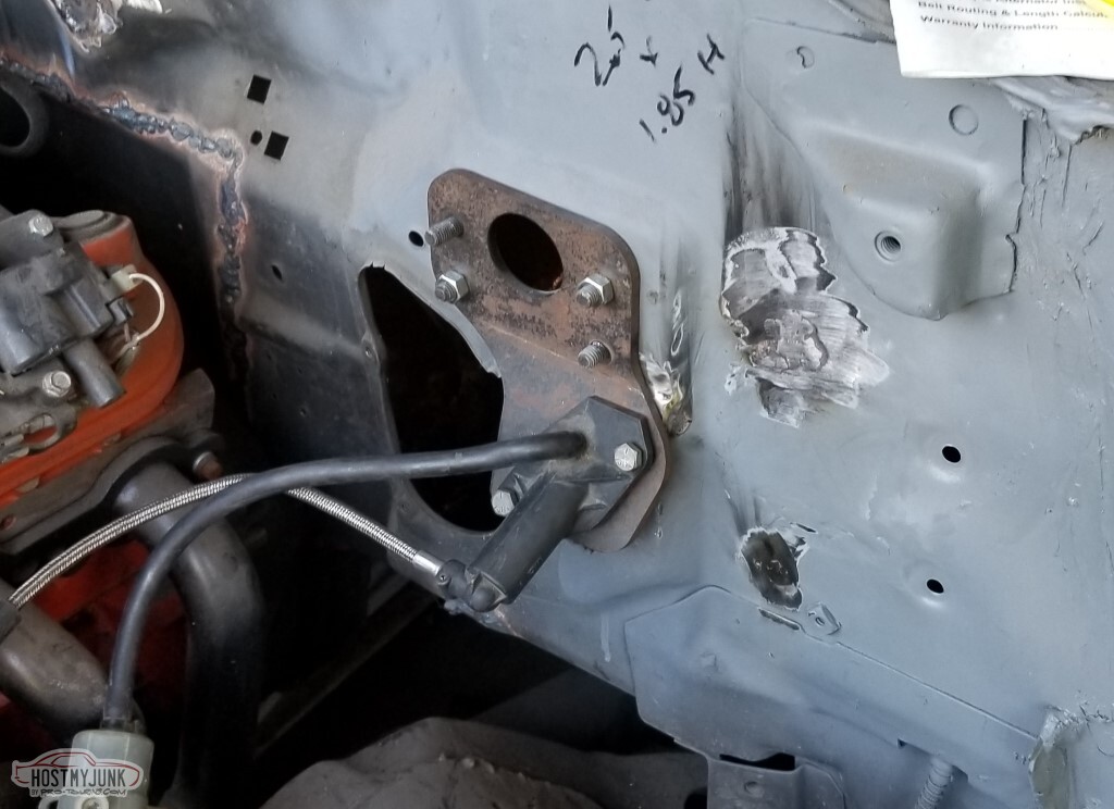
Oh yeah, the pass side rear LCA mount is still horrible.
If you've forgotten - at various points over the past thirty years, both of the LCAs have torn their mounting buckets free. The driver's side was roughly 1992, and the pass side maybe 1999-2000? The pass side was put back in offset forward so it had to move

Cleaned up a little but I have A Plan.
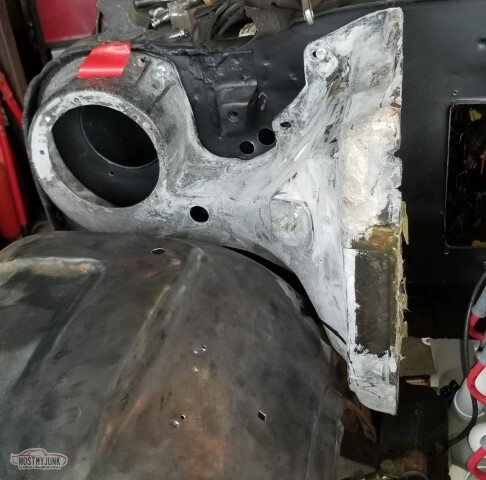
I want to reinforce the mount to the frame with gussets. First cardboard...
then metal.
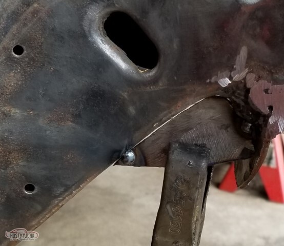
Same inboard
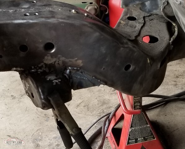
and also same on the driver's side (not pictured, this is another as-welded pic of the pass)
Upon reflection these may be insufficient - it's the same thickness as the frame but much thinner than the LCA mount box. It's not going to make it weaker, at least.
Also if you had any fear at all that I'd become a competent welder, let these pictures reassure you.

Time to correct the overly high front suspension. Spacers have 2.5" of, well, spacing. 3/4" electrical tape to note where to cut.
And now they're only 3/4" + the adjustor height. Is that enough cut? Only time will tell.
Front end is pretty much cleaned up. I've ordered a better torch (since we can't go get one) and once it's here I'll finish up the underside and can start painting.
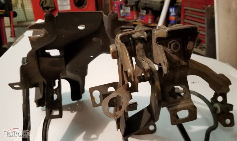
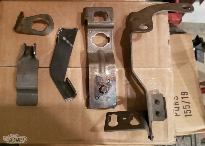
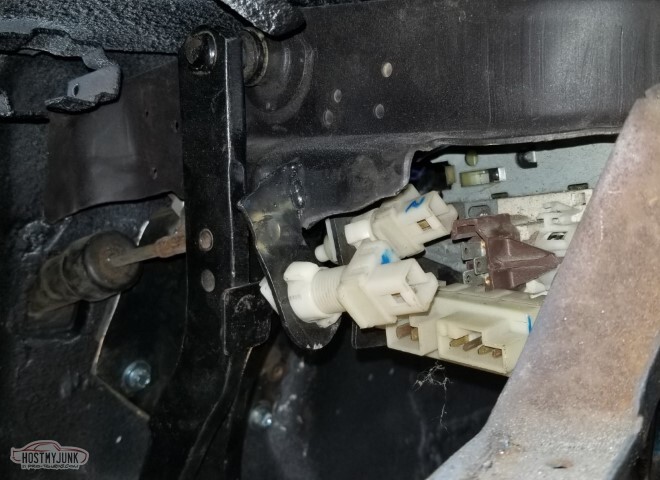
69 pedals on the left, LS-era Camaro pedals on the right. I need to adapt all the switches and their associated bracketry to the 69; should all be pretty straightforward except for the clutch switch that's engaged when the clutch is fully depressed; I don't know where that point is yet and there's no method for adjustment on that bracket.
-
05-15-2021 #74
-ɹoʇɐɹǝpoW-
- Join Date
- Jul 2002
- Location
- Mesquite, TX
- Posts
- 4,901
Finished up the floors, seam sealed all the stuff I'd done.

Next up on the interior - Lizardskin sound and heat deadening.

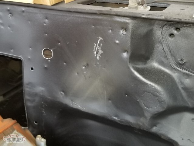
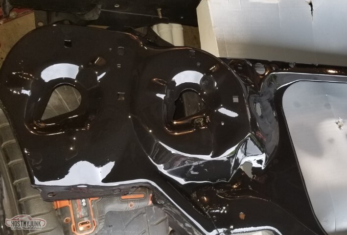
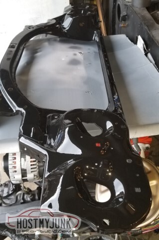
On to the front - cleaned up the welds, scuffed the existing primer...
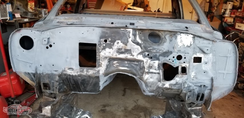
and then primed it all with the Summit Epoxy Primer.

And then shot paint. It's the "Majic" Tractor and Implement Enamel from Tractor Supply. I shot the color about two hours after the primer so in theory it'd have a chemical bond. The online reviews for the Majic are mediocre at best but for firewall UV resistance is not so much a thing.<br><br>If I'd had more hardener, I'd have done a second coat. If I'd had gloss instead of matte, that would have been better... but I didn't.
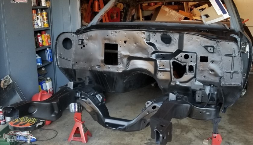
Still came out pretty good, if I don't say so myself.

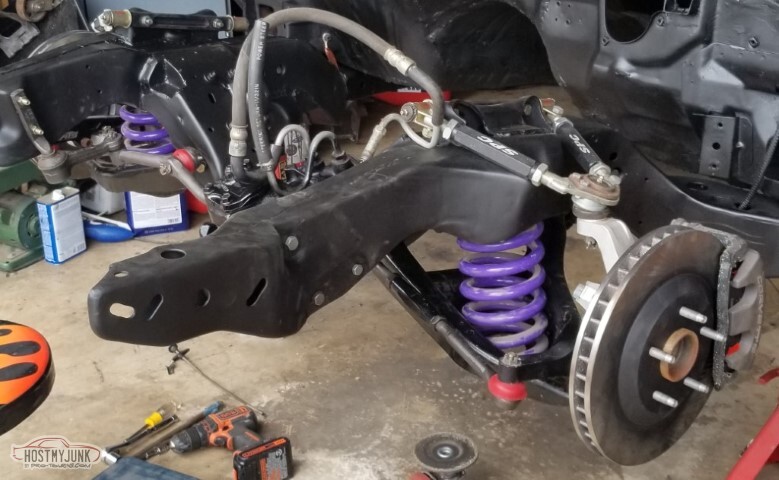
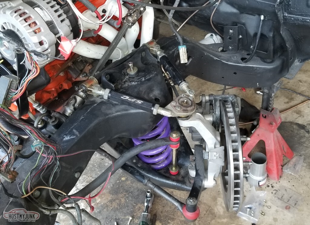
So let's put things back together. Here I've got the spring and spacer in, and the jack is lifting the LCA until it just starts to take the weight off the jackstand. It looks like I'm pretty close to horizontal (at least for a line between the LCA pivots and the LBJ) here.
And again with the other side installed.
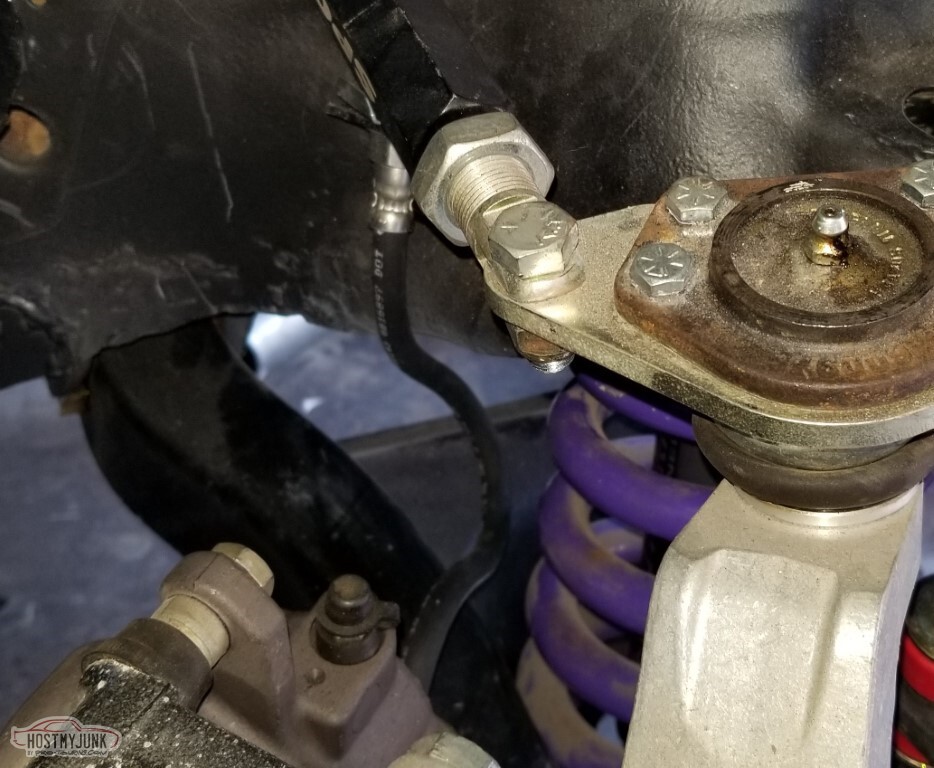
So I look at the passenger side, and the LBJ has a cotter pin on it, the upper does not - which tells me that I didn't torque the upper (and if you look really closely, you might notice the rear allen bolt holding the steering arm on isn't torqued down either)
Driver's side LBJ has no cotter pin.
And, in fact, neither does the UBJ.
Torqued all to spec, added cotter pins

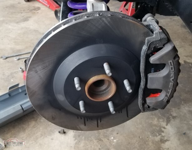
Replaced the rusty rotors with new ones (some rattlecan for the center). Dug out the pads for the brakes, and the brake pad clips and got those installed, torqued the calipers and the abutments (and added loctite).
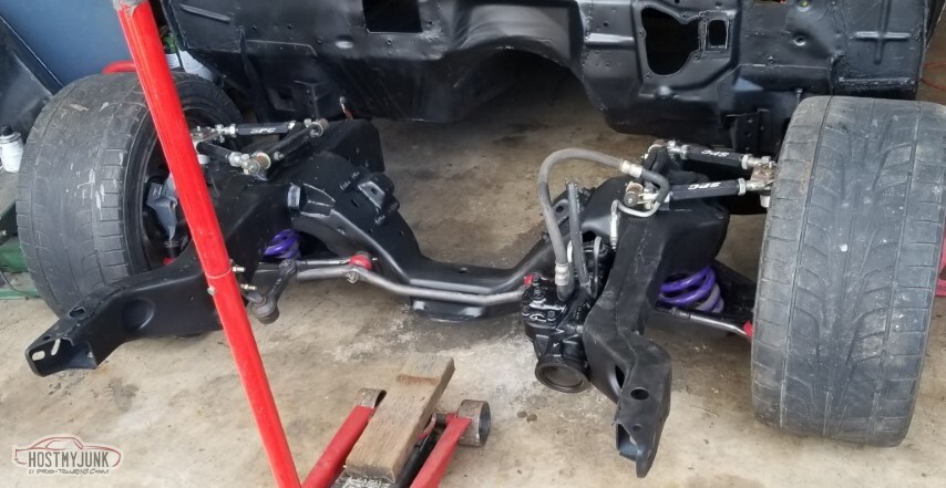
Added the steering box, tie rods, idler arm, torqued, cotter pinned, greased.
 2003280014_tn.jpg"></a></td><td>
Had to see how it looked on the ground.
5 1/2 inch clearance at the crossmember.. I think with the engine and body on, it should be pretty close to the 4 inches I was looking for.
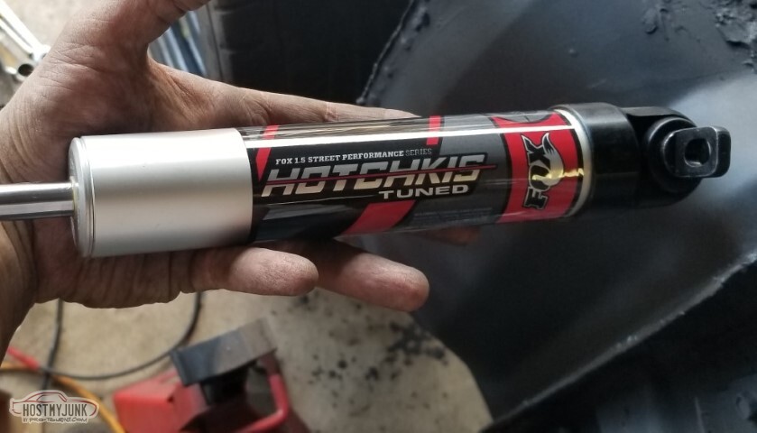
I got front shocks. They're partially installed - I can't find the J-nuts for the LCAs. I may have to mail-order or venture out into the infected zone.
So when I pulled out the box that had the brake pad clips, it was all the little parts I'd ordered in 2005-ish. Not quite sure what I was thinking for some of these.- 2 packs of 8 each LS exhaust valve seals.
- A crank bolt
- Four banjo bolts (two different part numbers - 22163795, Camaro front, and 10286122, maybe Cadillac rear?)
- 2 separate 12160244 (Air Charge Temp Sensor)
- 20 brass washers
Suppose it's the two temp senders that confused me most. I *think* that I have an ARP crank bolt somewhere too.

I started to put the wiper linkage in but then I remembered (when I saw) - back in 97 or so, I broke off the pin that runs the second arm for the driver's wiper. I need to weld something in there, so I pulled the linkage back out.
Installed the replacement parking brake cable. Still need to hook up the rest of the parking brake setup.
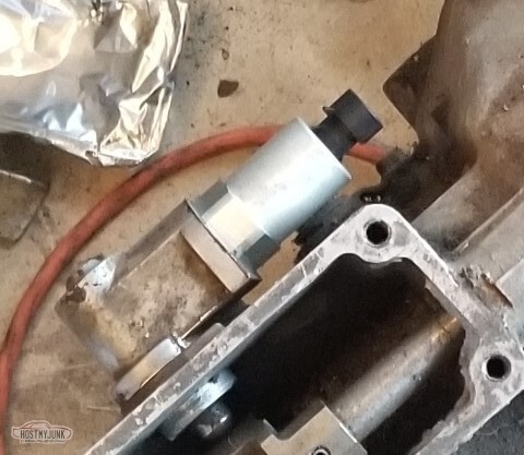
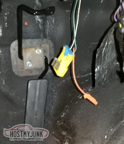
Also installed the replacement reverse lockout solenoid. It's much smaller than the one it replaced. Relatively sure I have a replacement for the reverse switch too, but don't want to install it and then break it off during reinstallation.
-
05-15-2021 #75
-ɹoʇɐɹǝpoW-
- Join Date
- Jul 2002
- Location
- Mesquite, TX
- Posts
- 4,901
So this update really has three main things and several small things I did but they were all interleaved; I've tried to lump them together for readability.
First up: I broke out the LizardSkin coating for the interior.
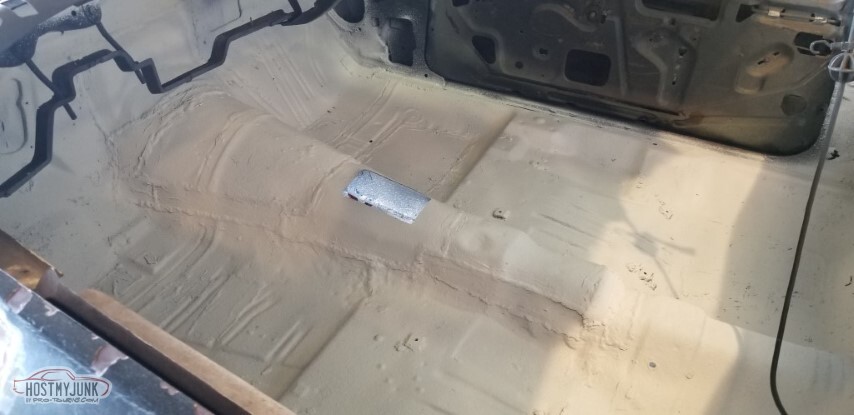
First, of course, I put down a coat of epoxy primer (not pictured). Then once that was dry (and it was warm enough outside), two coats of LizardSkin Sound Control.
It's got more of a texture than regular paint. Sprayed easily enough with their gun.
I'd opted for the "black" for the sound control (although it was at best a grey), and the "white" for the ceramic thermal insulation. The white is definitely white. Two coats here too.
Never has such a rough floorboard had such nice coatings applied.
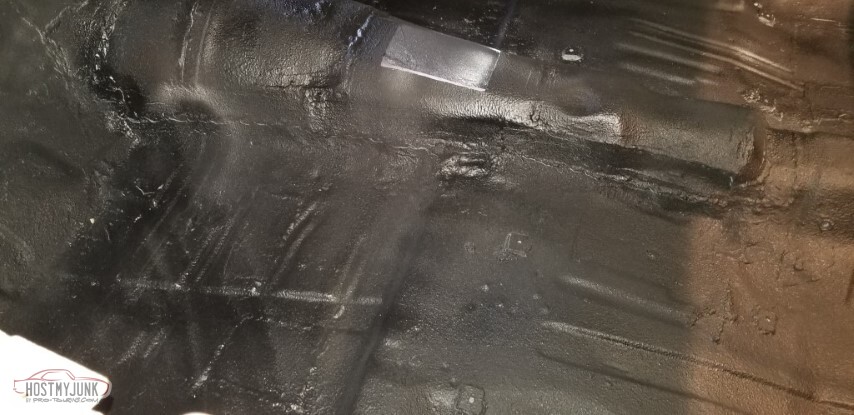
Followed up with a coat of regular catalyzed black just to protect.
Floorboards: complete!
I've mentally lumped things on the to-do list as "regular" and "really hard" based on my assessment of my own skill level and my understanding of what needs to happen. Removing the smog equipment parts of the headers has been marked as "hard" because I am still a lousy weldor. Doing the rear gears was marked as "hard". Sorting the electrical *should* be marked as hard but it's not, and I'm still looking forward to it.
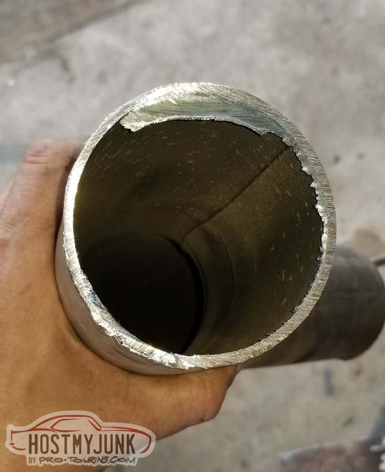
The header primaries are 1 5/8" I. D. I picked up some 1 3/4" tube and it seems to match the O.D pretty well. Let's start with this one that doesn't have to be pretty. The 1 3/4" has been cut in half lengthwise so it can make patches easily.
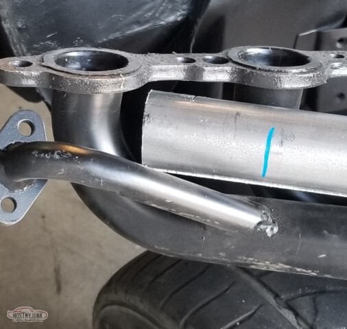
Yep, this is what gets cut off.
And here it is with its replacement.

Oh. That's not so bad, once I get through the welds it's really a small spot to weld up.

It's not pretty - I don't know that I understand what the welder was doing (even on "B", it went into spray mode quite a bit) but it looks like it'll work.
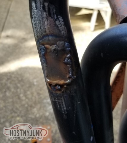
The moved O2 bung looks like it'll work too.
Filled with optimism, I moved on to the other two ports. This is not pretty but should suffice.
And again here - unpretty but probably okay.

"I've got a great idea! Let's use the TIG to knock down some of those bead-piles"
-- leads to blowing through, twice. Sigh.

The internet said "To remove the coating from Hedman hedders, you should take them to a machine shop and have them hot-dipped overnight, or sandblast". Yeah, with the coronavirus and not having a cabinet big enough.. neither of those will work.
What I found was if you get most of the coating off with a wire brush, lacquer thinner works well for what remains.

Not all that well cleaned up near the collector, but I don't think I care.
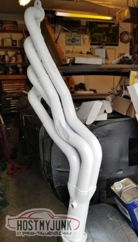
VHT white header primer, followed by their white header paint. If there's a leak, I should be able to see it on the white.
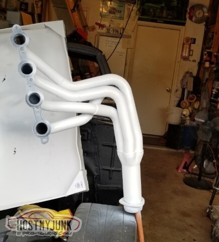
same thing on the other side.
The header paint cans give a heat cycling recipe to cure the paint and seal it from chemicals - 200 degrees for 30 minutes, let cool, 400 for 30 minutes, let cool, and then 600 for 30 minutes.
I don't have an oven and I certainly can't let the engine handle it. What I do have, though, is a cheap heat gun. You can see the difference in the finish as it warms.
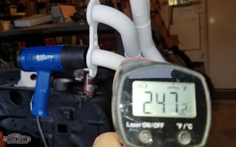
On "low" I can get to ~275, and on high I saw 380. I can't do the 600 degree final heating but it should protect some from my greasy hands.
The second pass on the second header is still pending but otherwise they're ready to put somewhere safe, as soon as I figure out where that might be.

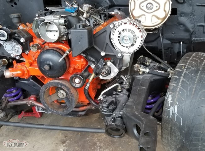
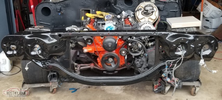
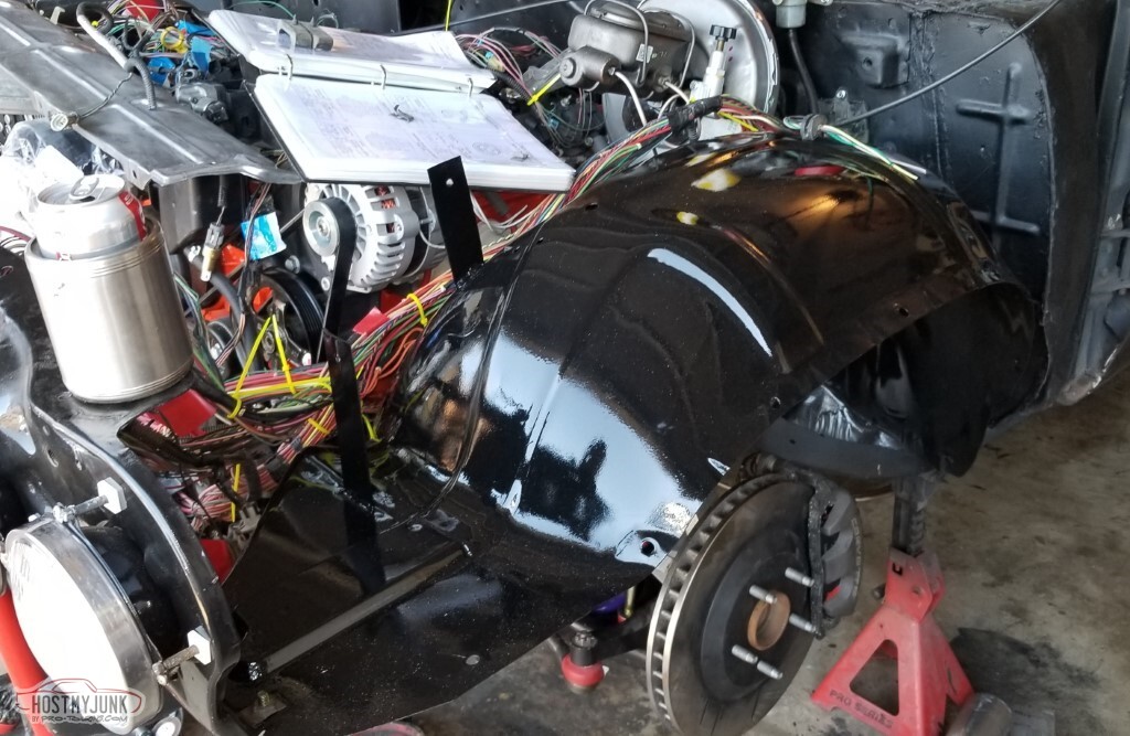
So with the frame painted and the suspension *mostly* installed, no reason not to put the engine back in. Hopefully I'll be able to do it without tearing up the new paint.
Poof, it's back in.
No, there's no in-progress shots; between the sloped driveway, the wide expansion joint, and the lip between the garage and the driveway I had my hands full.
Did I get it back in without scratching things up? I was very careful.
Yes. Yes, I did.
No, wait, crap. No I didn't.
The back of the engine is too close to the firewall for this cotter pin to clear. Sigh.
I'll have to scuff and reshoot. Or ignore. Pretty sure there's a wire channel that bolts to the firewall right around here.
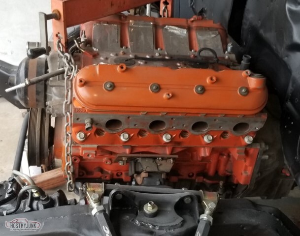
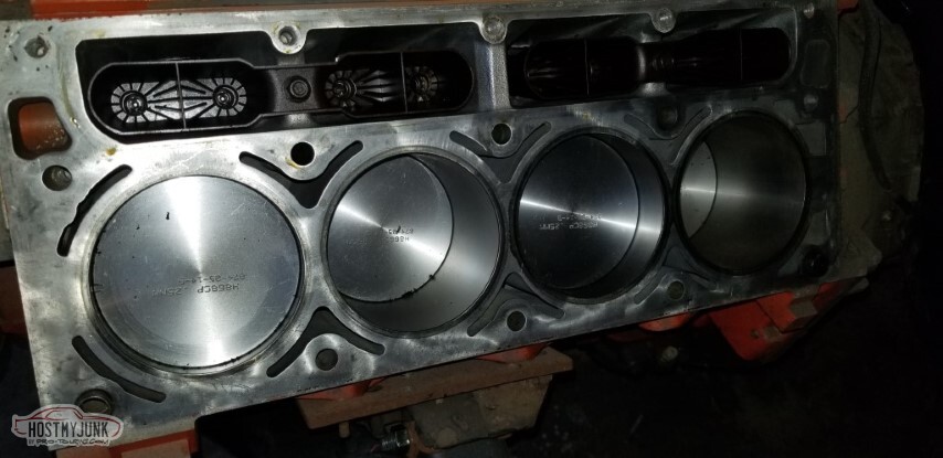
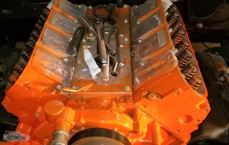
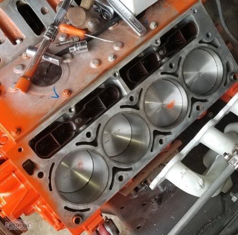
One of the concerns I had was if - in the fourteen years since I built the engine the cylinder walls had coated themselves with rust.
They had not.

Also as shown.
New head gaskets, new head bolts.
Did wipe them down with more oil and clean out the dirt that had made its way in.
Heads back on (not torqued yet). Put additional orange paint on them.
A concern:
I'd mentioned back in '06 (post #12) that one of the pass side small head bolts at the valley needed a helicoil. When I pulled the head bolts this time, a small chunk of helicoil came out of one of the driver's side head bolts. I find myself wondering how many other helicoils are on the engine and how bad they are. Suppose it'll become obvious, one way or another.
 2004040035_tn.jpg"></a></td><td>
Also there were other things that were done.
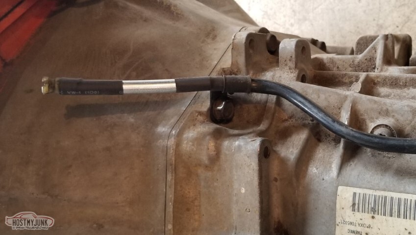
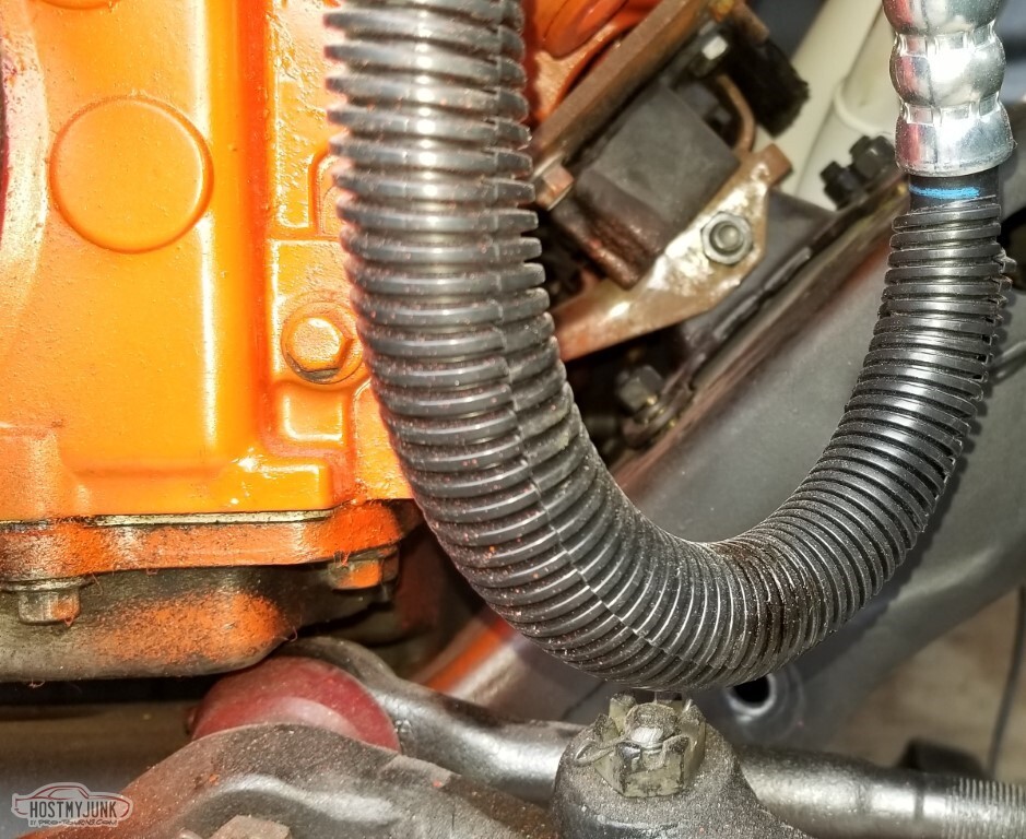
So apparently when I was doing rust repair on the pass side floorboard or on the tunnel, I got the vent tube for the transmission too hot. This is not going to vent well.
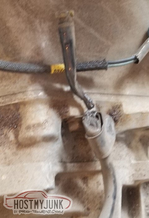
Heat-shrink and 3/8" steel tube to the rescue.
I found the front brake hose brackets. They were each in different places in the garage so it's probably more impressive to me than to you that I found both of them.
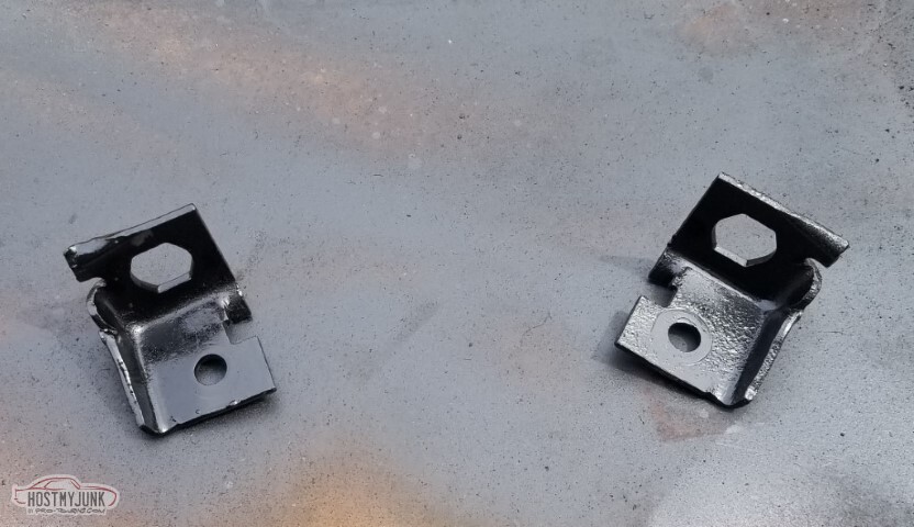
Also I bought a set of LS-era pedals (as mentioned in post 73) just to get the switches and these brackets, so I can add them to my pedals.
I can't add the clutch start switch until I know where the bottom of the clutch travel is - but I'll probably do something that bolts to those four holes on the left rather than try to weld it in.
Otherwise the switches line up pretty well.
Cut the protruding part of the column base off for clearance for the clutch rod.
Reckon that's it. The rest is assembly, near as I can tell, or at least I hope.
-
05-15-2021 #76
-ɹoʇɐɹǝpoW-
- Join Date
- Jul 2002
- Location
- Mesquite, TX
- Posts
- 4,901
This kinda bounces around and I've reordered the photos so things that look out of sequence.. might be.
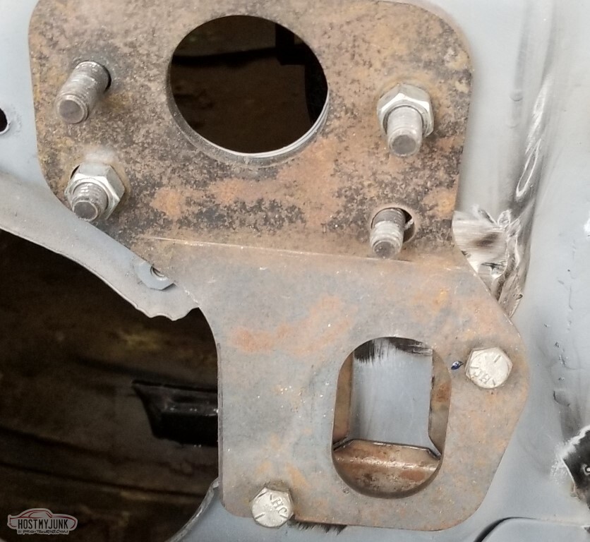
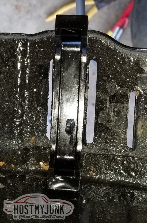
Strip-caulk ("Strip-calk") will seal the clutch bracket to the flange.
Accessory brackets: installed!

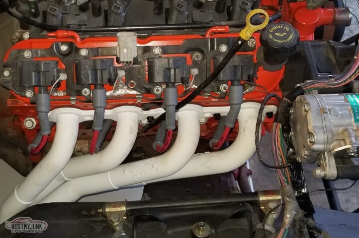
Headers: installed!


Tie rod end: Hits the pan!
Sigh.
Internet seems to think that raising the engine up a little, or lowering the tailshaft, or replacing the grease fitting with an allen plug, or heim joints, or a longer/taller idler arm and pitman arm are the fix.
I'm not going to stress on this currently.

This is how far I can turn the wheel (it's about 1 1/2 turns right and 1 3/4 left). Is this enough? I don't know.
It looks like the driver's tie rod is longer than the pass side a bit, so some adjustment might help too.
Also bolted up the clutch bracket and the master cylinder.
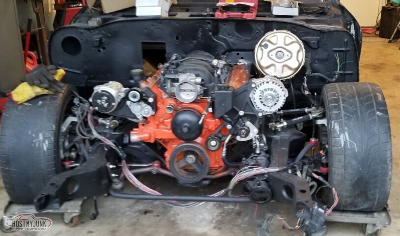
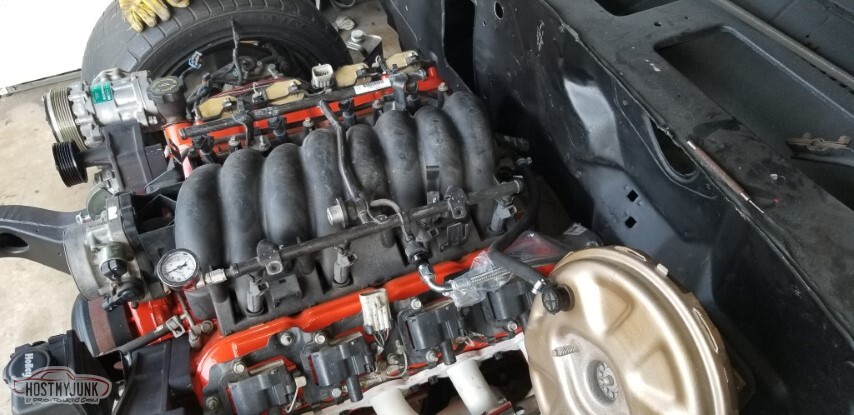
Dug the wiring out and started to install it.
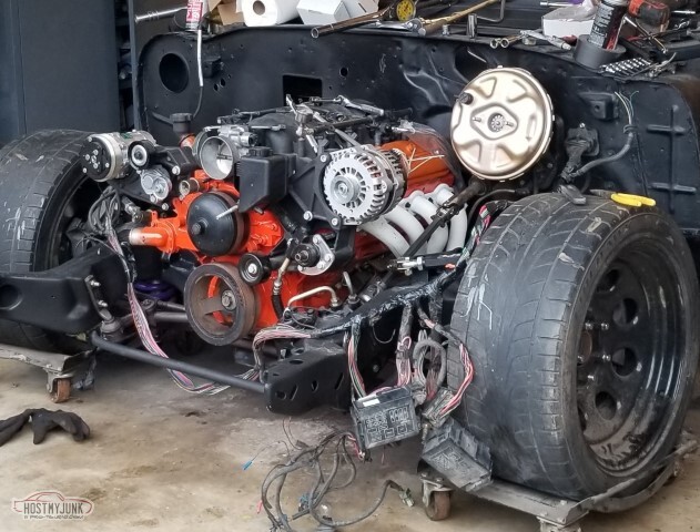
Starting to look more like a car.
I wasn't happy with the "feel" of a couple of the small head bolts when I was checking the cylinders.
After I'd bolted everything up, I decided to tear it all back down and helicoil the two questionable boltholes (see blue marks on the valley cover)
Helicoils installed.
The Jegs branded graphite header gaskets probably would have sealed pretty well, based on how well they stuck to the heads.
New shiny paint on the valve covers too, and the brake vacuum hose installed (it's 3/8", had to heat it a bit with the heatgun to get it over the port on the intake)
PS pulley installed. Waiting on the last smooth pulley to put on the tensioner.

Poof, then the deliveryguy shows up and I can install the belt.

AC box is not installed.. but it fits and clears everything.
The funnel and the white cardboard under the front of the car are because I had a concern about the seals and how well I installed them, and how well they held up to 14 years of sitting. The answe is "just fine" - no drips
(knock on wood).

A round of sanding and more resin for the AC box. It's close and I probably could have just used filler, but nope.

Let's go all the way: spark plugs, coils, plug wires, dipstick installed.
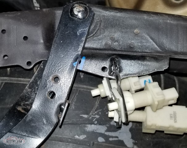
So my AC controls are broken? I *think* it can be welded back in place. Not a thing I wanted to have to worry about though. Wondering if I have a spare to just swap out. Wondering if I do, will the face be in better shape?
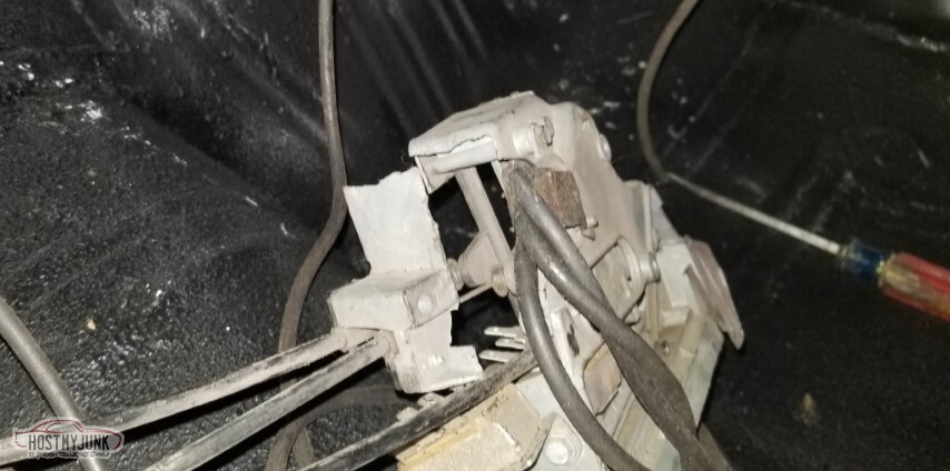
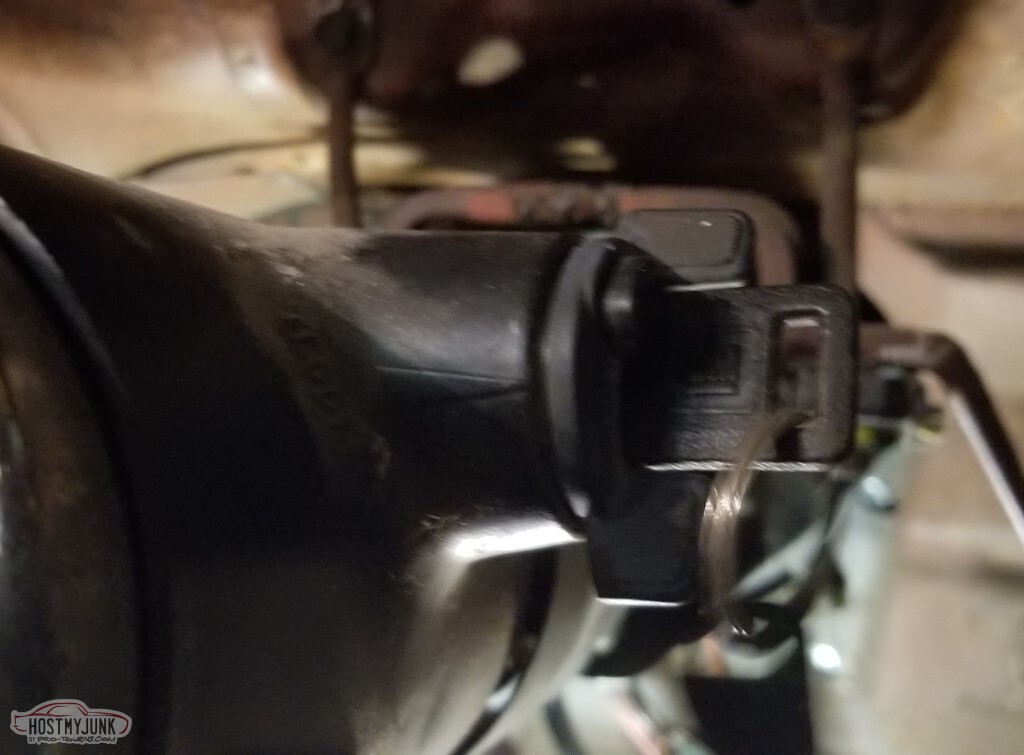
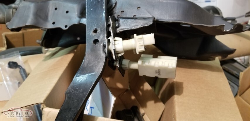
Also this will be an issue - the brake pedal switches and the column connectors want to be in the same place.
And that would be why. The brake pedal is attached to the booster (with the threaded rod at full extension); the clutch is where I put the switches. Obviously I need to pull this out and move the switches. I'd used the old switch as a baseline for where to put these but it was apparently very optimistic and/or the clutch bracket really shortens the throw.

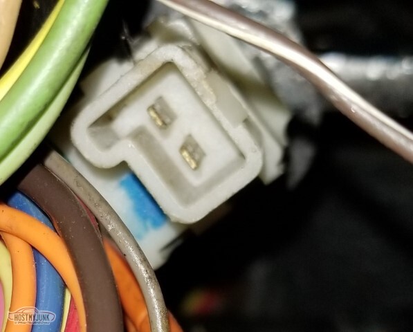
This is part of the AC; I don't know how the plug is supposed to stay in the firewall but it certainly doesn't want to do it for me. Also it's dirty and needs cleaned.

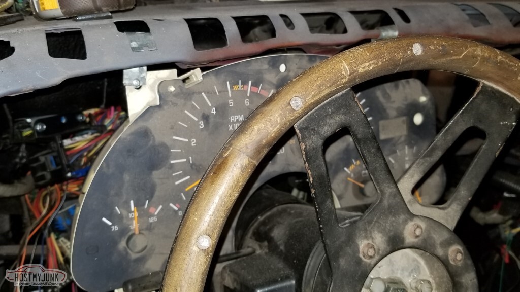
Speaking of dirty, I pulled the old steering wheel out and bolted it up. I intend to use this wheel - but it's going to need epoxy to make it more solid and a lot of cleaning.
Pulled out the shift knob and handle, too. Don't know where the correct bolts for it went, added to the shopping list.

Not pictured:- The windshield wiper pivot pin that I broke in ~97 or so (see post #73) has been replaced
- I dug around in the attic for the wiper arm, and found all sorts of additional LS parts - valve covers, another set of coils with brackets, on top of the set of rods and pins, and the lifters and rockers... where did all these come from? I've never parted out an LS. I really don't know how they got there.
- Also pulled out the core support for cleanup and installation. It's going to need a lot of cleanup.
- Not quite sure what to make of the fresh air flap that goes inside the cowl (see post #36) but I cleaned it a little. It's not in as good of a shape as it was back in 03.
- Master cylinder is bench-bled and installed (no lines yet though)
-
05-15-2021 #77
-ɹoʇɐɹǝpoW-
- Join Date
- Jul 2002
- Location
- Mesquite, TX
- Posts
- 4,901
I'm sick already of having wires strewn across the top of the engine. Let's do something about it!
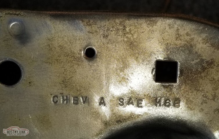
I'm really more amused by this stamping than I should be.
Similarly, I'm much less concerned about this rust than I should be.
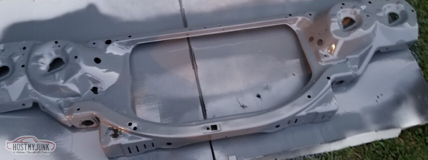
Cleaned up enough, epoxy primer time. Night falling here, so time to let it dry.
Wiper arm with new pin.

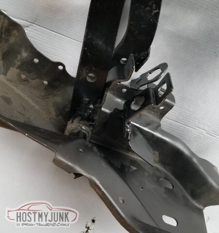
Pulled the pedal assembly out. The blue line is where it ends up in the car.
Not pictured: Cut it up. moved the switches, painted, put it back in (yeah, I should have taken pics).
Gloss "Majik" paint from Tractor Supply looks really nice. Wish I'd used gloss on the frame and maybe also the firewall.
Overall view.
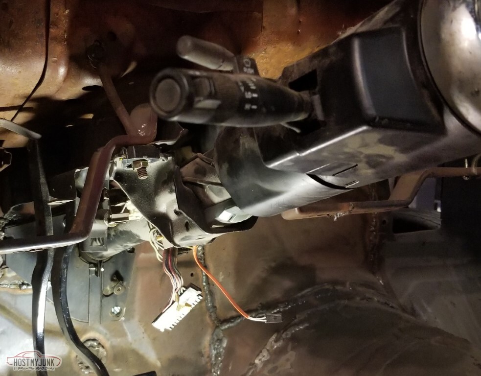
With the switch mount moved, these two connectors will coexist.

Since most of the wiring that was on the floorboard is actually going to be behind the dash, it's been run up and over the column.

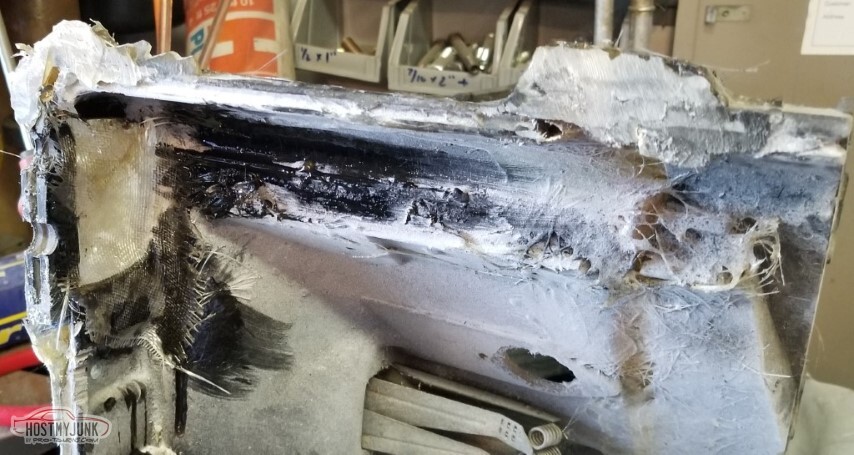
So hopefully my skill level is sufficient to weld this back together; I suspect that the AC control assembly is not going to be cheap.

So I asked the wrong question before I started: I'd asked if I was good enough to weld this. The correct question would have been whether it was a weldable material.
It is not.
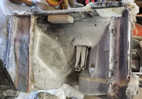
Reinforcement via pop-rivets is an option though.
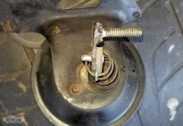
On to the cowl flap thing. This is a "rubberized fiber" gasket material, also pop-riveted to the housing. It flexes, it holds it close. Should work.
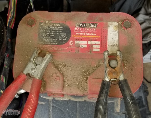
Pulled out my optima battery.
After sitting on a shelf for fifteen years, the battery was producing about 4v. With 2a trickle charger for a couple of hours I got up to 6v; I don't know how well this is going to improve from there.
The cowl vent flapper lever thing was broken - but no reason I can't make a new one out of some 12ga or so steel with a bolt welded to it, and then pop-rivet that to the remaining arm. So I did.
Bolted up the cleaned and painted core support. It looks really nice.
Working my way through the wiring, here's the first real snag I've bounced off of. This is the switch that tells the cruise control that I've started to depress the clutch ("Clutch anticipate").
And this is the connector that looks like it should go with it - but obviously not the same.
More research required.

Also - I don't think I have enough pedal travel on the brakes. I don't know if it's the booster (which I'm pretty sure has been on this car for decades) or the new master (which apparently I didn't mention - it's a stock 69 Chevelle disc/disc master) but I think it's about an inch, give or take, of travel and even with the little bench-bleed plugs in the ports it's not getting "firm". Investigation required. Also I don't know where the "proper" clevis pin is; the bolt I'm using has more slack than I'd prefer.
Engine harness partially installed. Cruise control partially installed. Need to get the inner fenders cleaned up and painted so I can mount things to them.
Need to figure out a mount for the PCM and for all three fuseboxes. Also need to figure out how to mark the "IP Fuse Box" so I can tell what fuse goes to what item - I won't have the little door that has it listed on the back.
-
05-15-2021 #78
-ɹoʇɐɹǝpoW-
- Join Date
- Jul 2002
- Location
- Mesquite, TX
- Posts
- 4,901
So I think I've found part of the issue with why the brakes don't seem to be building pressure: deep master...
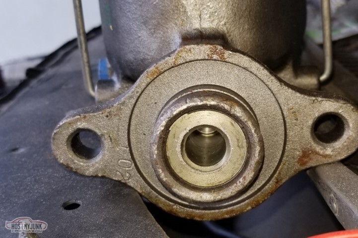
and shallow pushrod.

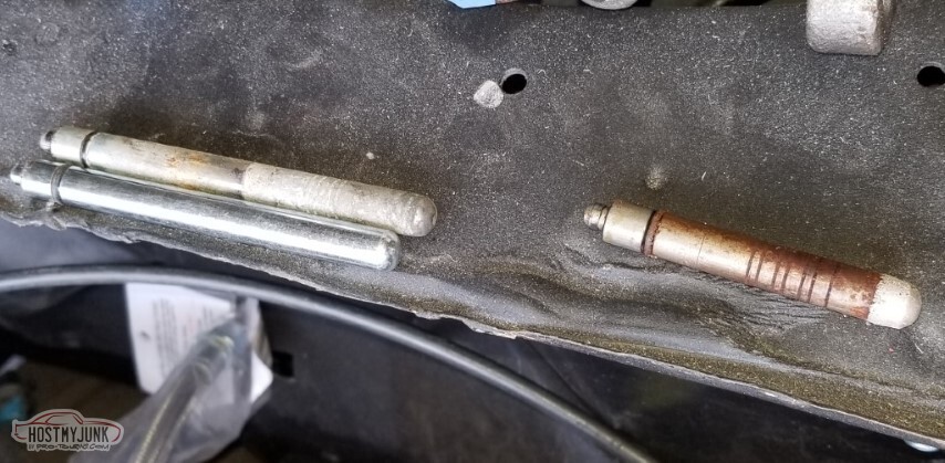
So I ordered a long pushrod. Then I found a spare (once again, where the heck did I get a spare?). Old short pushrod to the right.
When I tried to insert the new pushrod, the 50 year old rubber cracked. Sigh.
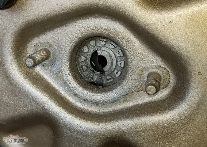
So - time to replace.
Not pictured, because the pic didn't come out: New booster came with an adjustable rod, which was a nice touch.
The feel is definitely different now. The pedal is much higher off the floor and firm.
The mount for the brake light switches has to be removed.
Again.
It's going to interfere with the column again so I won't be able to use it quite the way it started.
Not pulling the pedal assembly out again so I'll have to do my welding in-place (fun).

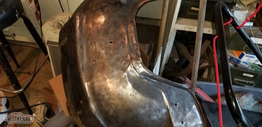
The inner fenders need cleaned up to get ready for running the wires.
I've used wire-brush-on-an-angle-grinder to clean up the underside.
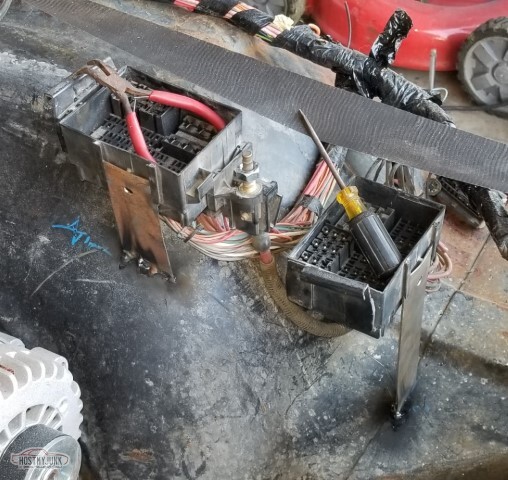
Vaguely mounted the fuse boxes (tape indicates the likely inner edge of the fender).
Pass side underneath is clean, and part of the top. I'll need to figure out mounting for the ECU, somewhere not in the way of the AC box.
The headlight buckets and battery tray have been primed.

Painted too.
Also found the missing gas pedal assembly.

And then there's little stuff.
I think I've figured out how to do the El Camino's headlight/dimmer switch with the Camaro harness.

Sigh. When I said "no leaks", I apparently spoke too soon. Hope is that this is about all that's going to come out. Fear is that under pressure it'll be a lot worse.

The little hole-of-unspecified-purpose (maybe radio antenna?) has had a plastic plug put in, and covered with strip-calk
.
Also I think I'll have to replace the AC ducting.

Last edited by derekf; 05-15-2021 at 07:39 PM.
05-15-2021 #79
-ɹoʇɐɹǝpoW-
- Join Date
- Jul 2002
- Location
- Mesquite, TX
- Posts
- 4,901
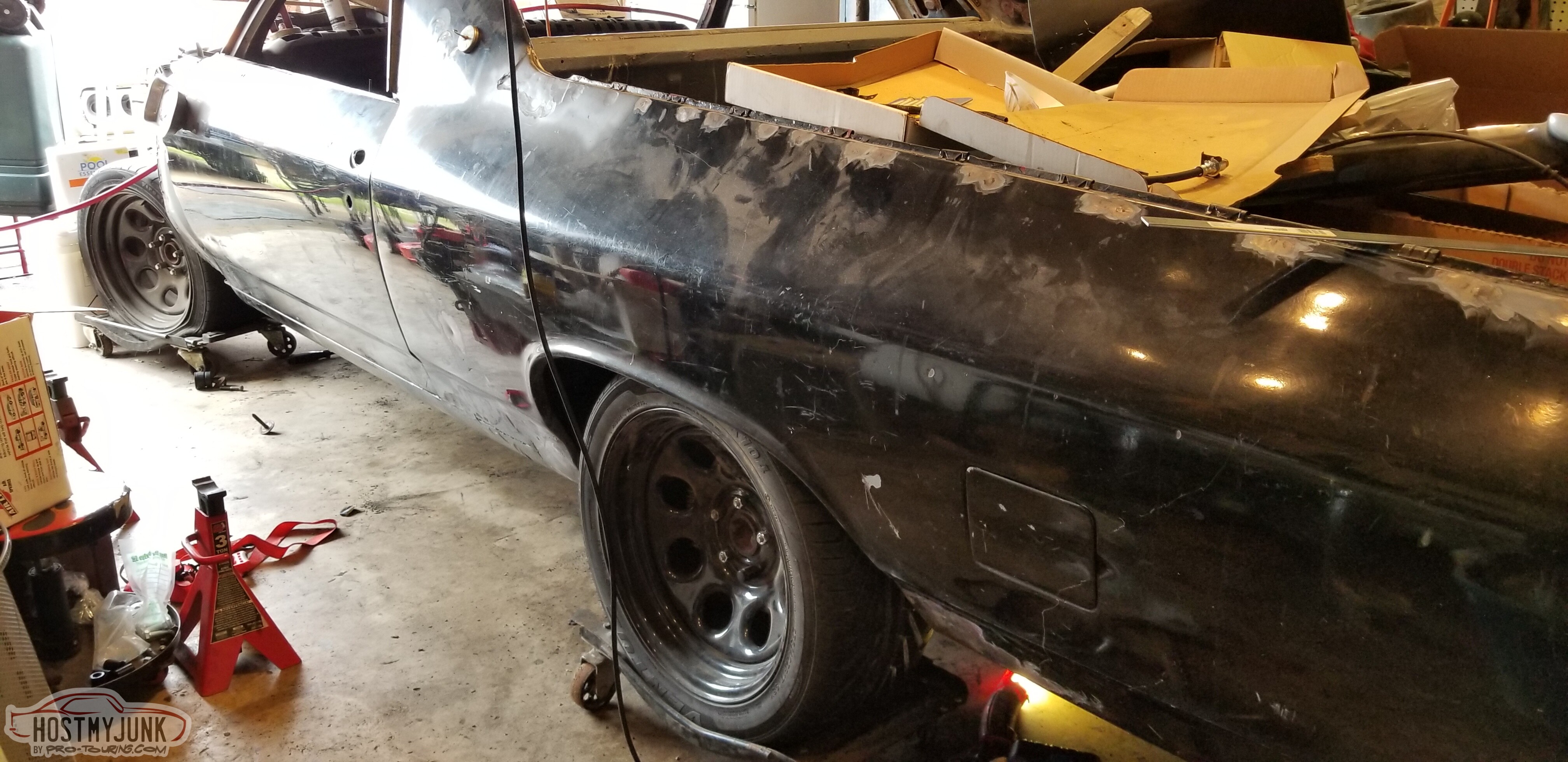
Headlamps installed, and the car is sitting on its own four wheels for the first time in a long time.
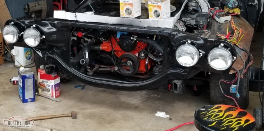
It's *very* low. In fact, it's too low -- the front crossmember is a little less than 3 inches from the ground; I'd like to see four.
I'd thought to maybe try to put the computer on the back half of the pass wheelwell but there is no room at all.
No room under it, neither.
I found all the missing parts for the gas pedal; painted the lever, installed a new pedal, and mounted it.
Have not found the missing windshield washer reservoir bracket yet.
I had thought that the brake on the driver's side was off center and the whole thing needs to be shimmed out, but somewhere after this picture it just figured itself out.
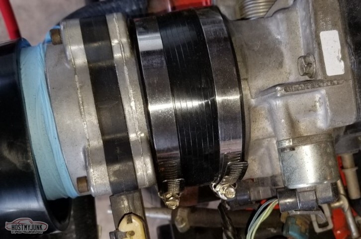
Got the coupler to attach the MAF to the throttle body. It's a 4 inch coupler, and came with an insert to make it 3.9" on one side so it attached tightly to the throttle body. This is the Spectre piece.
I bought two braided lines (Fragola) to hook the tank to the pump. On both I thought "hey, I'll get a 90 on one end and that'll go on the pump side.
No, the supply side there's not room for a 90. Trying to put it together the other direction really didn't work well.
Proof that you can screw up a flare on NiCopp line too.
I've mentioned before that the garage is magic and keeps disgorging useful things of unspecified origin.
Today's discovery was an old Ridgid 37 degree flare tool. Would have been nice if this had appeared before I bought the one at the bottom, but I can't complain much; I bought one and now I have two.
Seriously though - where do these things come from?
Since the car was too low, need to adjust the spacers.
Started just shy of 2"
Believe I read at one point that with the way the A-body suspension is set up, a half inch change at the spring is a full inch of ride height.
So, let's test that: spacers now set to 2.5".

I took the springs out by unbolting the UCAs. While I had them out, I realized that none of the bolts holding them together were tightened (and one was missing the nut!).
Corrected.
I put the Camaro radiator in as a test. It fits, somewhat, but it feels so tiny. Maybe the stock El Camino radiator can work with the LS?

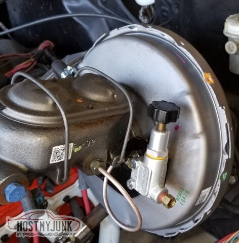
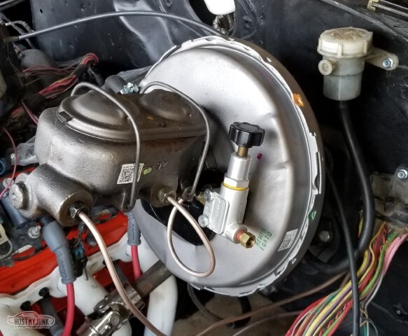
I made a bracket to mount to the master cylinder to hold the proportioning valve. I think this will work Just Fine.
The loop going to the valve isn't as sharp of a bend as it appears here.
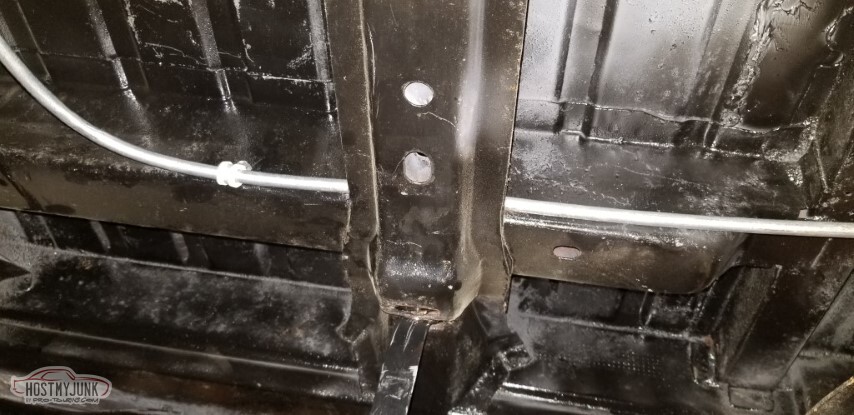
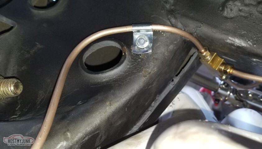
And then I went ahead and plumbed out the front brakes too - MC to a tee fitting, and the two halves of the T to the brackets at the wheels.
Even secured the line to the back of the crossmember.

While I was down there, I noticed that I was missing an oil pan bolt.
Why am I missing an oil pan bolt?

Tee fitting.
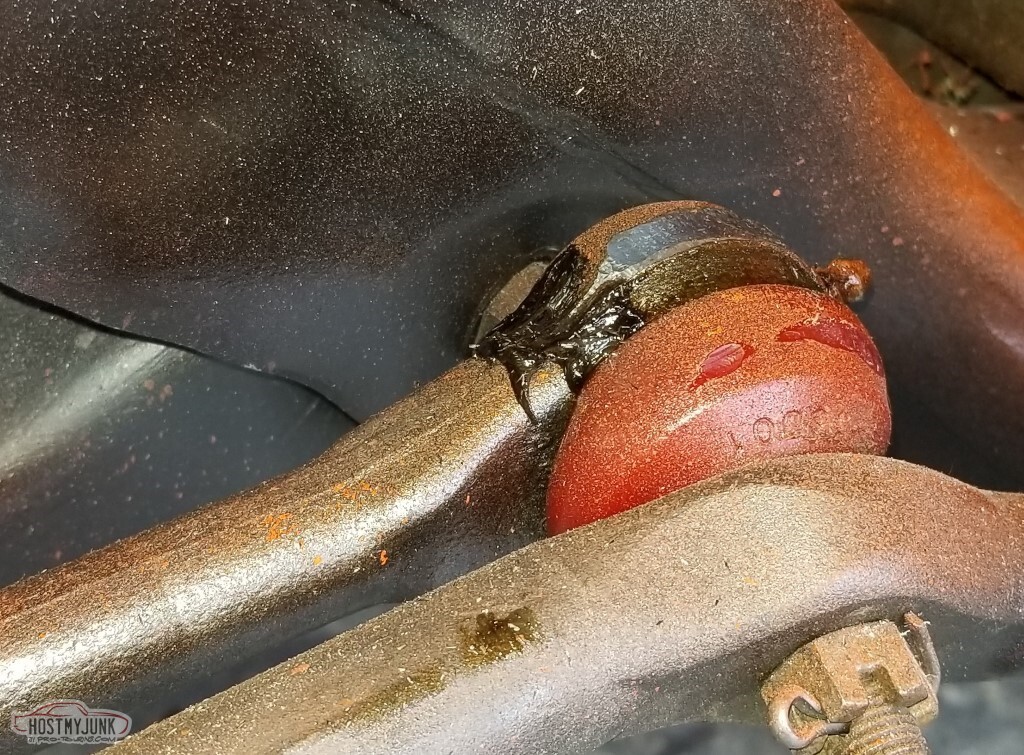
I mentioned back in post #76 that the tie rod ends were hitting the pan. One suggested fix is to lower the rear and raise the front of the engine a little. To do this, I started with a short transmission mount, and it is indeed shorter (and I could cut and reweld my crossmember, but I'm not going to do that)

With just the tranny mount done, I still hit but it's hitting much lower - I was hitting the grease fitting before. Will raise the front of the engine just a little.
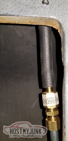
I got 69 Chevelle disk hoses, figuring that the travel is a known value and they'd be long enough.
They are not.
These are 11 7/8" long and even with the travel being limited by the tie rod ends hitting, they're not long enough.
Oddly enough, there's a hose for a 1980 Chevette (H86572) of all things that has the right ends and is 14 1/4 inclues long. That may be the answer.
Need to figure out how long I need to add first though - there's longer ones for trucks or motorhomes.
Also the magic garage has eaten my banjo bolts, which is not such a big deal since the hoses aren't long enough, but I do wish the brake fluid hadn't tried to run out the ends of the hoses.
Drained what didn't dribble out back into the bottle with a big syringe.

Tried again with the Fragola hoses, no right angle on the supply side this time. This works better.
Tank sliding off the jack has definitely ruined the finish.
Back in 2010 I bought a 98 Trans Am. The exhaust was "too loud", she said. I replaced it with a quieter setup and stored this one in the attic for whatever reason. Somewhere along the way, this heavy thing was set on top of the Chevelle's windshield and promptly broke it.
Sigh.
Apparently the reason was so I could use it later.
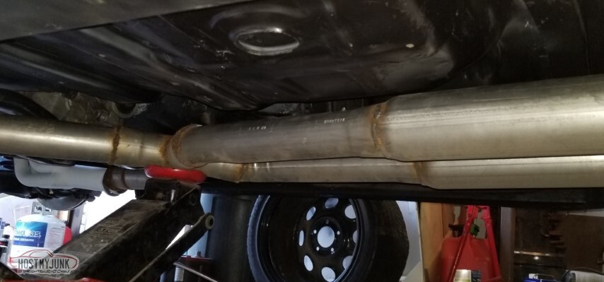
Also, the internet was right back then: these are some really really ugly welds.
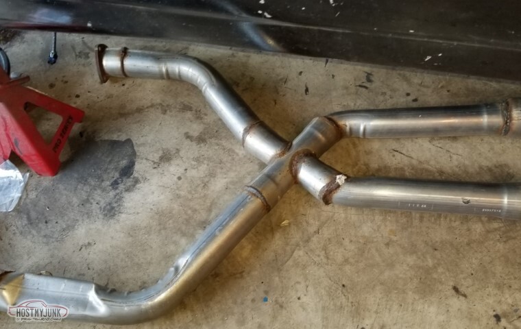
It fits up under the car well enough, I suppose. Needs about six more inches before the "mufflers" on each side to get back where there's more clearance. Also needs massaged to meet up with the collectors.
I did get four feet of 3" tube from Summit and a tailpipe expander from O'Reilly so I should be able to adjust as appropriate.
Driver's side is a little short to line up with the collector (and I still need to weld in the correct collector things to connect to the Hedmans).
It'll be fine.
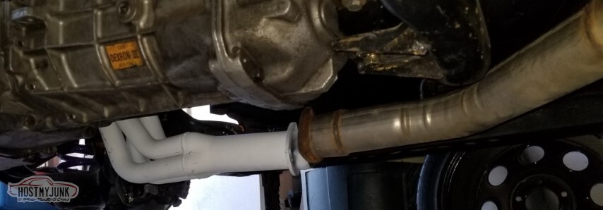
<tr><td>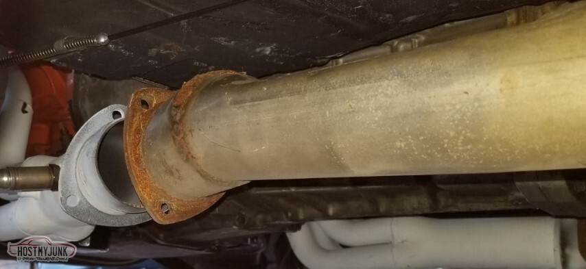
May need some bends - it doesn't quite line up with the bumps in the transmission crossmember. We'll see.
Pass side is a little better. Seems to be close to the cutouts in the crossmember on that side too.
Oh - and no pic, because I don't know what to take a pic of: the oil leak I mentioned earlier this week was not, as I feared, the rear main seal. It's coming from the dipstick or the oil level sender or somewhere similar. Don't know where yet, but at least it's not telling me I need to pull the engine back out to fix it.
05-15-2021 #80
-ɹoʇɐɹǝpoW-
- Join Date
- Jul 2002
- Location
- Mesquite, TX
- Posts
- 4,901
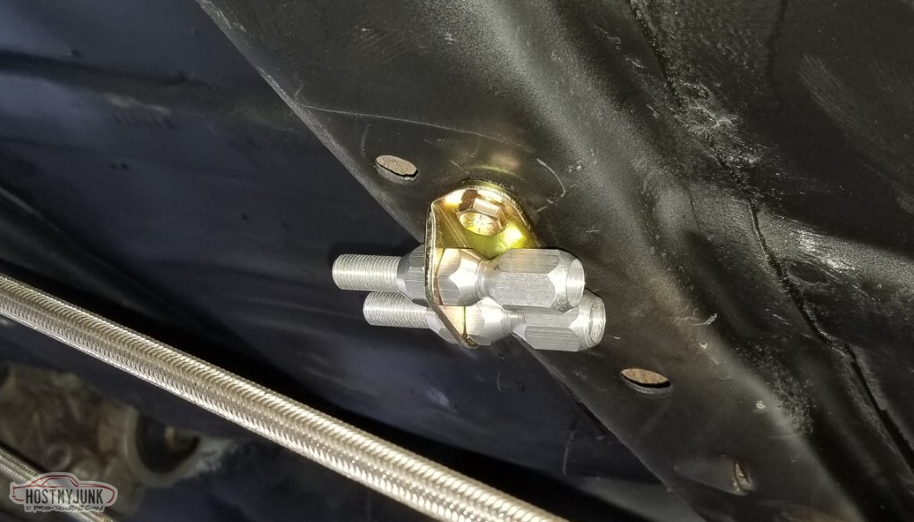
Ran the rear brake line.

Also the nutsert/rivnut tool arrived, so I was able to mount the emergency brake cables. This worked pretty well.
Finished cleaning up the inner fenderwells, epoxy primer time.
Think I'd mentioned that the shocks didn't want to fit in the lower control arm holes.
2021-05-14 edit: doesn't look like I had
The internet suggested opening up the holes a little, so I did. The J-nuts took up a lot of the space I just added...
... and didn't survive me trying to actually screw things into them.
Plan B: Pull the suspension apart again, weld 5/16" nuts to the LCAs at the holes.
Helpful hint: The round spacers are not so you can get an extra quarter inch of drop; they're so the bolt-heads don't bounce off the shock body. On the other side, I opened up the holes a little and offset the nuts outboard a little, that worked better.
No pic of the welds, because I'm still an abysmal welder.
With this, the front and rear suspensions are both complete.
I found the washer bottle bracket I mentioned repeatedly over the past few weeks! It's right where it should be.
Inconveniently, that's right in the way of one of the fuse boxes.
Went ahead and cut apart that old exhaust to make it work. No wonder it's so heavy - that's 1/8" thick tubing!
Routing of the parking brake cable things.
After putting the shorter transmission mount in, the tie rod end still hit the oil pan -- by a lot less, but it still hit.
I loosened the bolts for the driver's motor mount and jacked up the car by the back of the pan.
With .105 of a gap there at the engine mount, the tie rod clears by .070.. so I put some .070 washers under the motor mount, which should clear by .035. (please don't check my math)
Now I can get this sort of steering angle (less when I have, you know, tires).
Also just to be sure, I took a die grinder and cleaned up the top of the tie rods just a little bit.
I made some temporary mounts for the spare dashboard, just so when I applied power I'd have a thing for output.
Fun thing I hadn't noticed: this is a Canadian dashboard - it's in kilometers and liters and furlongs and such.
Painted the inner fenders inside and out with that Tractor Supply implement paint. Shiny!


And then I mounted them, because that's what you do.

The Chevette hoses arrived. I am not convinced that these aren't too long; a little worried about this position here, tight turn and maybe heavy bumps?
I got some radiator bushing things. They're "Nolathane", they're nice enough but when they ask if it's big block or small block in this case, there's an actual difference. These fit two of the four locations.
I also ordered an aluminum radiator because y'all told me to.

Next up is wiring.
I'm using mostly the 4th gen F-body harness, but I want to use the 60s headlight switch and AC controls.
Shared my notes on the headlight switch back in post #78, time to start trying to figure out the AC controls.
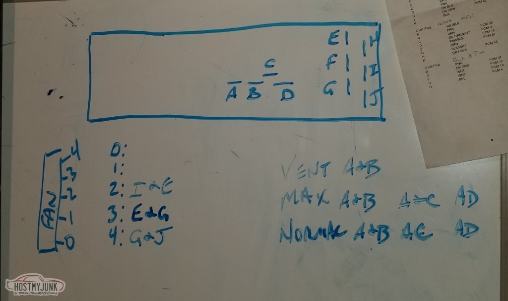
My switch is crusty, and probably original.
Initial testing only found the wiring used for med 1, med 2, and high.

With the aid of trial and error, and various places on the internet (no link because I didn't get enough info in one place to link it), here's the first pass of detail. There's a different style switch that I found information for (see the right side) but that's not what I have.
My switch - as mentioned - is crusty; the low and off positions were intermittent at best. Hopefully spraying it with electronics cleaner and cycling repeatedly will improve it.
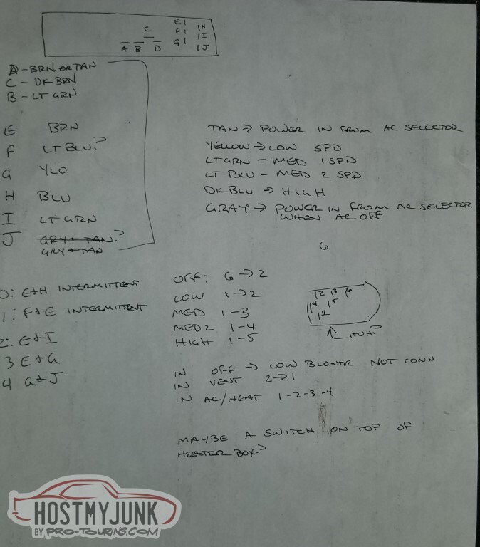
The way it does the AC compressor is strange. The top lever turns on the compressor in Max, Norm, and Heat. This switch - that doesn't actually work on mine - is only connected if the AC door is open (at least that's how it seems like it should work).
Here too, hopefully cleaning will help. I suspect the switch is hard to get and expensive. I suppose it doesn't have to be this kind of switch. I would like to have a better idea of how it's supposed to act though.
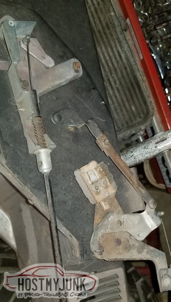
Another question that comes to mind is what goes where with the headlights.
High-beam is easy; there's only two prongs on the bulb, but there's three on the low beam.
Dug out the original harness from the car:
High beam is light green. From the back, that goes to the RIGHT side of the low beam bulb.
Low beam is tan. That's the top of the bulb.
Ground is black, go figure, and it's on the remaining pin on the LEFT side of the bulb.
(I'd actually expected the top to be the ground - and if you treat it as ground, you do get light out of the bulb)
Also grabbed the original AC harness so I have the connectors for the stuff above.
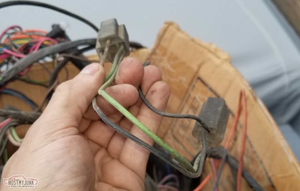
So with the inner fenders in place, I can mount the battery.
With the battery mounted, I can apply power to the harness and start trying to figure things out.
Yeah, that didn't go so well.
There were a lot of wires that I identified what they were (remember - I've got a bunch of cut wires, torn wires, crushed connectors, etc.).
With power applied and all the fuses in place, the seatbelt warning lit up on the dashboard (but nothing else). When I turned off the key, I got the "key in ignition with door open" chime.
Then I didn't and I don't know what changed. I could trigger it if I removed the "I/P 2" maxifuse or the IGN relay.
Think I've decided to go ahead and start removing unneeded wires. Also I've decided that the radio wiring - beyond the switched and constant power leads - can also go. When I remove things, I'm going to de-pin them from whereever they were rather than just going nuts with wire cutters. Hopefully I won't remove something I need, but I should be able to re-add if I do. It'll be a lot less daunting without all the fluff.
Most wires will need lengthened, or shortened, or both.

I'd get frustrated and move on to something else, and get frustrated there too.
Apparently when I was putting the brake lines together I was afraid to tighten ANYTHING. Everything leaked. Still does, a little, at the T-fitting up front. Not like this though.
Even after tightening, this one leaks right there at the banjo bolt. New washers, tighter, looser, doesn't matter.
Maybe the bolt is bad. Maybe the hose is bad, or maybe the caliper. At least I already have a spare bolt here, although that seems the least likely reason.
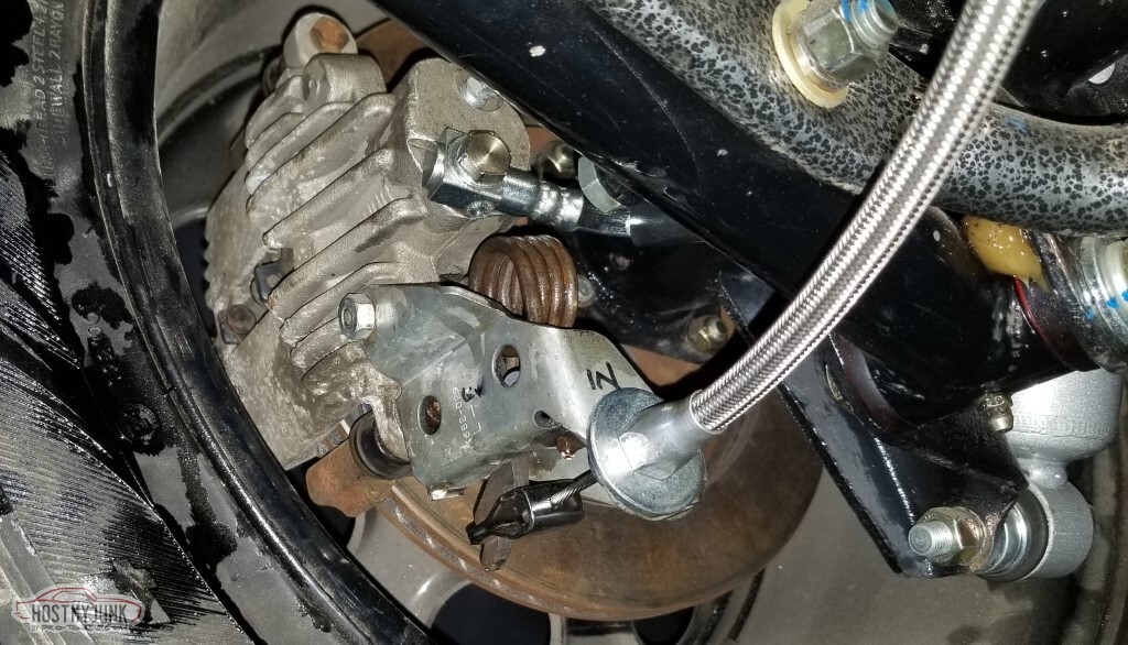
Worked a little on the exhaust - opened up the 2 1/2" side of one of the 2 1/2"-to-3" adapters so it can go on the collector. This will likely work out just fine. That really heavy tubing should weld pretty easy - not like I have to worry about burning through.
Also ran the rest of the fuel line. Hopefully it doesn't leak like the brake lines did.
It looks like I need a thin spacer up front to clear the Corvette calipers with the Soft 8 wheels.

 Reply With Quote


