

Results 81 to 100 of 119
Thread: derekf's 69 El Camino build
-
05-15-2021 #81

 -ɹoʇɐɹǝpoW-
- Join Date
- Jul 2002
- Location
- Mesquite, TX
- Posts
- 4,928

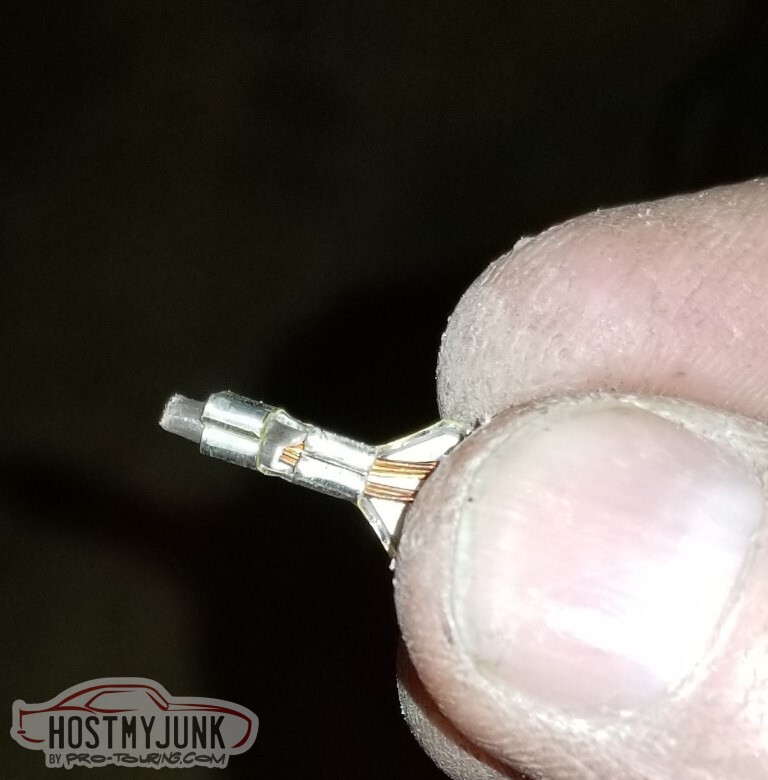
The stock F-body battery cables are too short, and I had no luck soldering them (I suppose I wasn't pumping enough heat in).
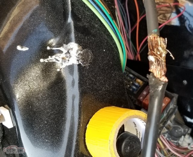
I do, however, have some convenient 3/8" NiCopp fuel line sitting around. That'd be a functional crimp connector.
And of course we finish with heat shrink.
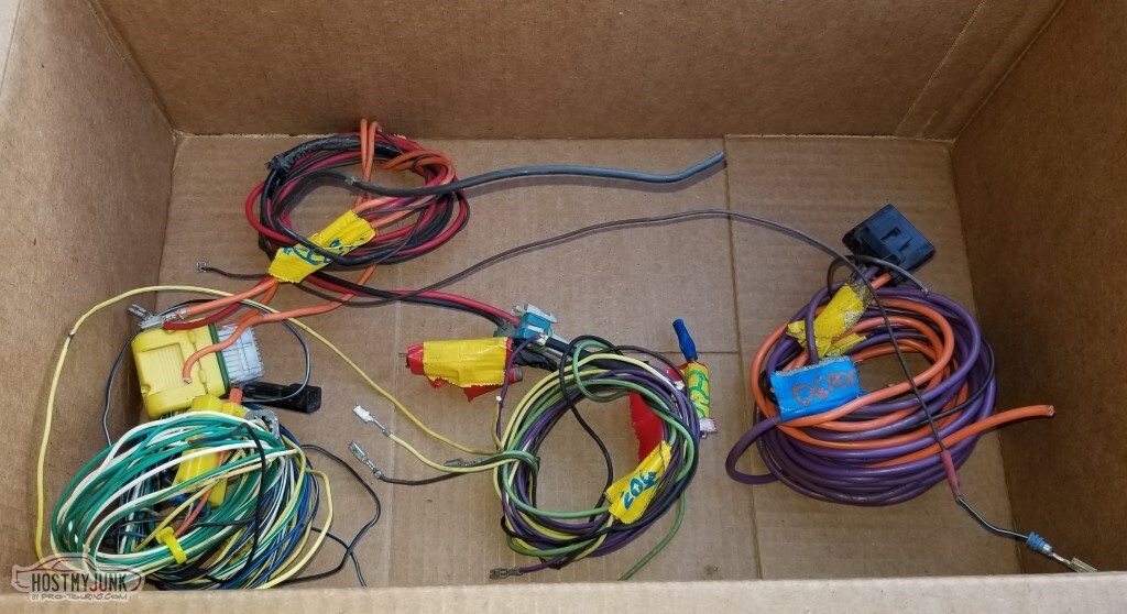
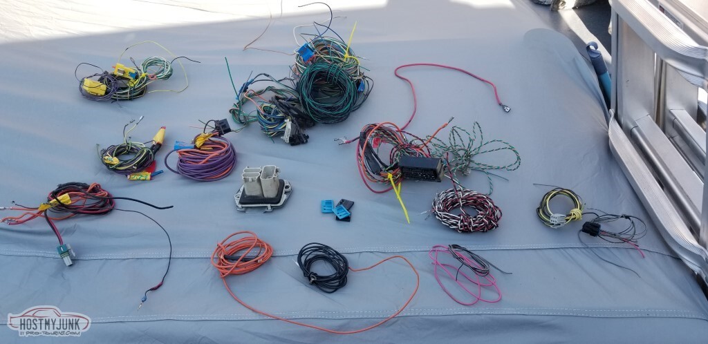
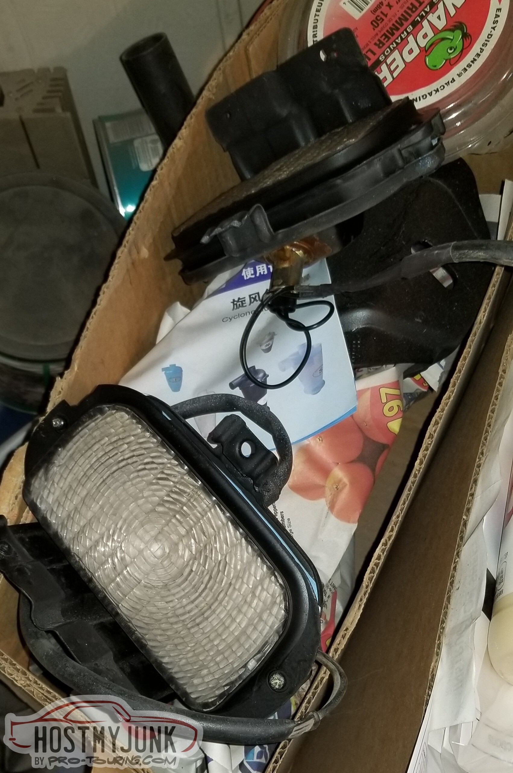
Started off small. Airbags, fog lights. De-pin if I can, cut at the bulkhead if not.
 2
2
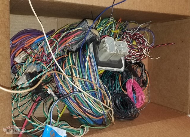
Won't need the ABS wiring.
And the pile grows. Won't need the emissions bits, the stock stereo connectors, amplifier, etc.
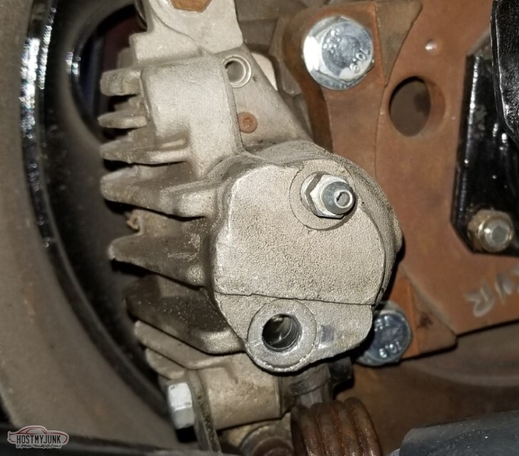
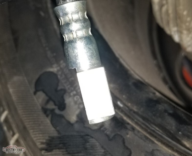
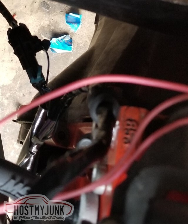
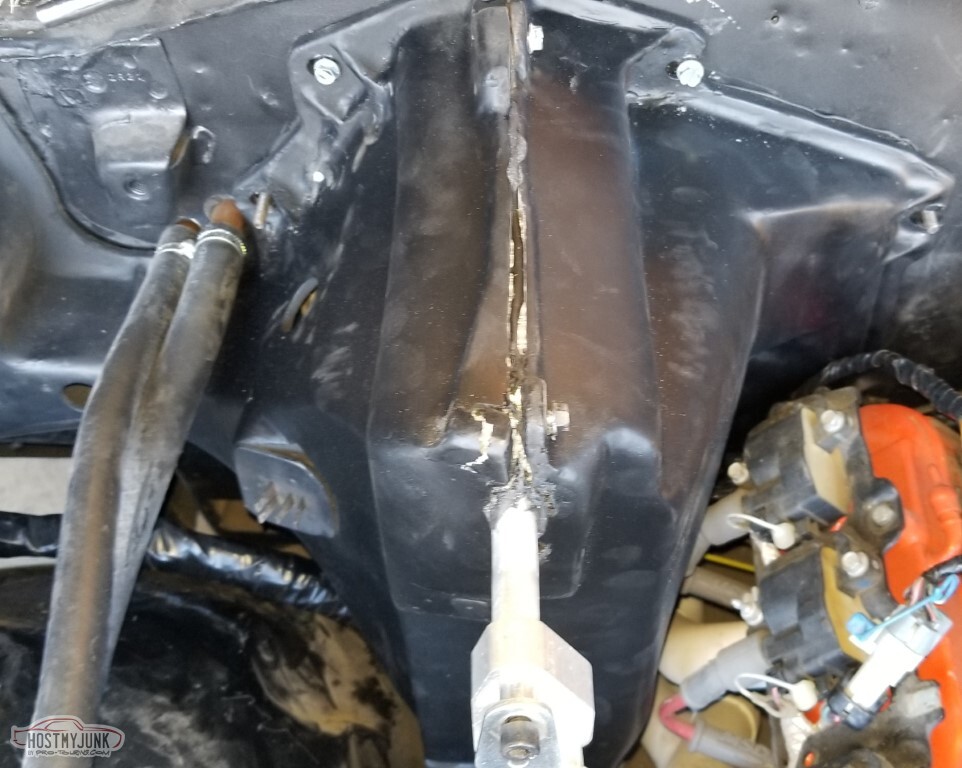
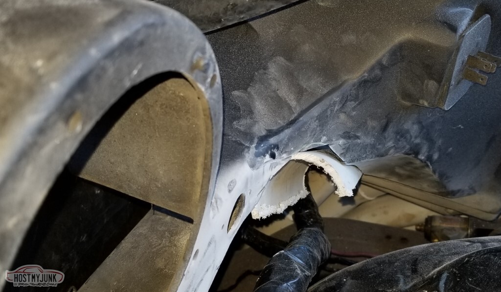
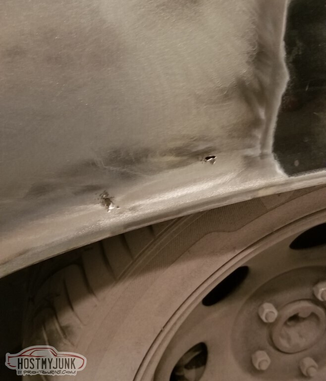
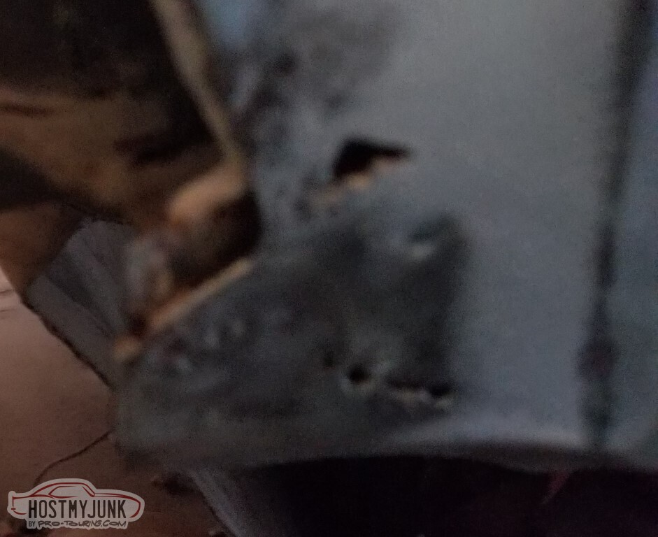
To hop to another issue - I may have neglected to mention, I have a leak at the rear calipers. This is the driver's side, it's fine.
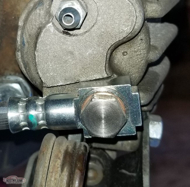
This is the pass side. There is DAMAGE near the banjo bolt, you might be able to see it.
The damage is from putting this hose on backward - it won't seal, and the edge dug into the caliper body.
I've asked the local FLAPS to order me a new one, they didn't even give me a price just said they've requested it and they'll give me a call. Not sure if that's a blowoff or not.
In this implementation, this pass side caliper is a 97 Camaro driver's side rear.
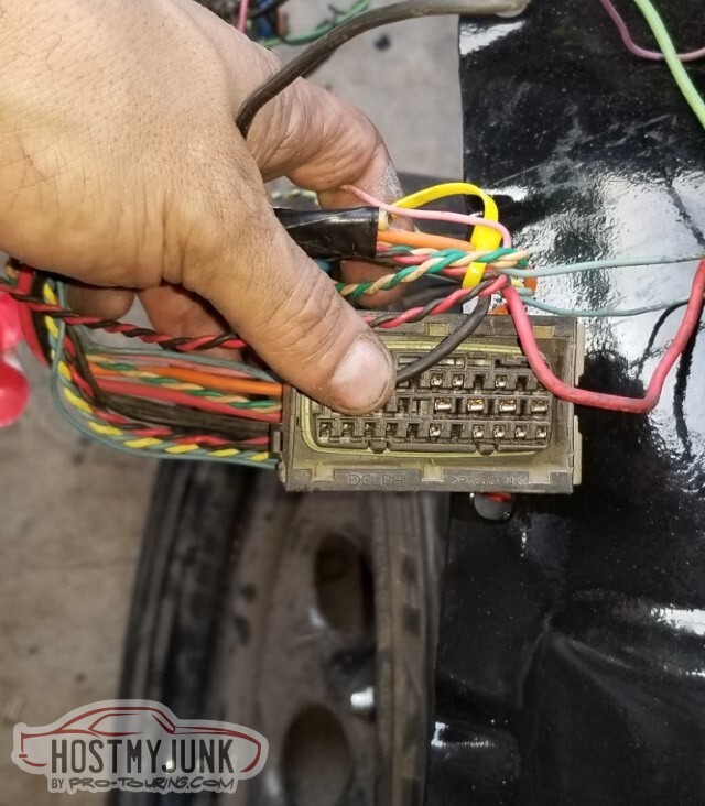
Pulled out more wires. This looks to be the same wires that were a few pictures back
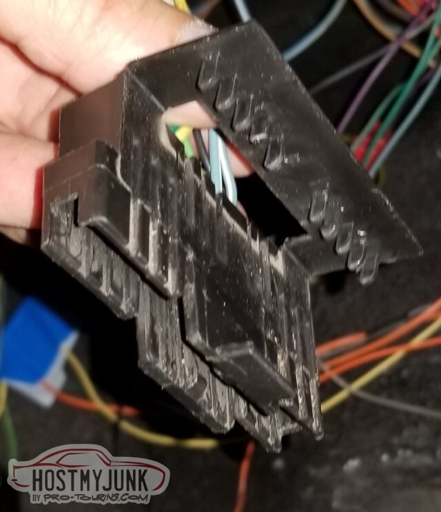
De-pinning the PCM is actually easy once you know the trick.
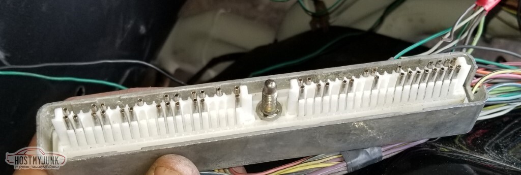
AIR pump, EGR, etc.
By this point I've got power to the car. Some things work, some do not. Right turn signal is a "no", and it looks to be because the pin in the column connector is bent over.
Tried to straighten it, no dice.
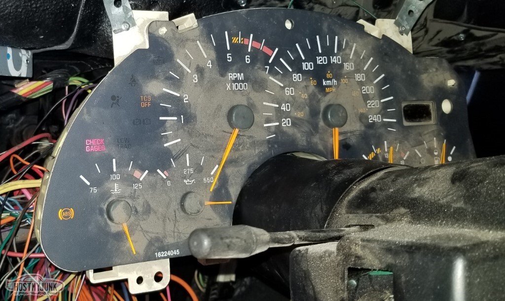
I am not convinced that this dashboard goes with this car (maybe an LT-era dash?). Not because of the metric calibration, but because nothing lights up correctly. High beam makes the oil pressure go sky-high (and then Check Gages comes on). Odometer never came on.
I don't need it.
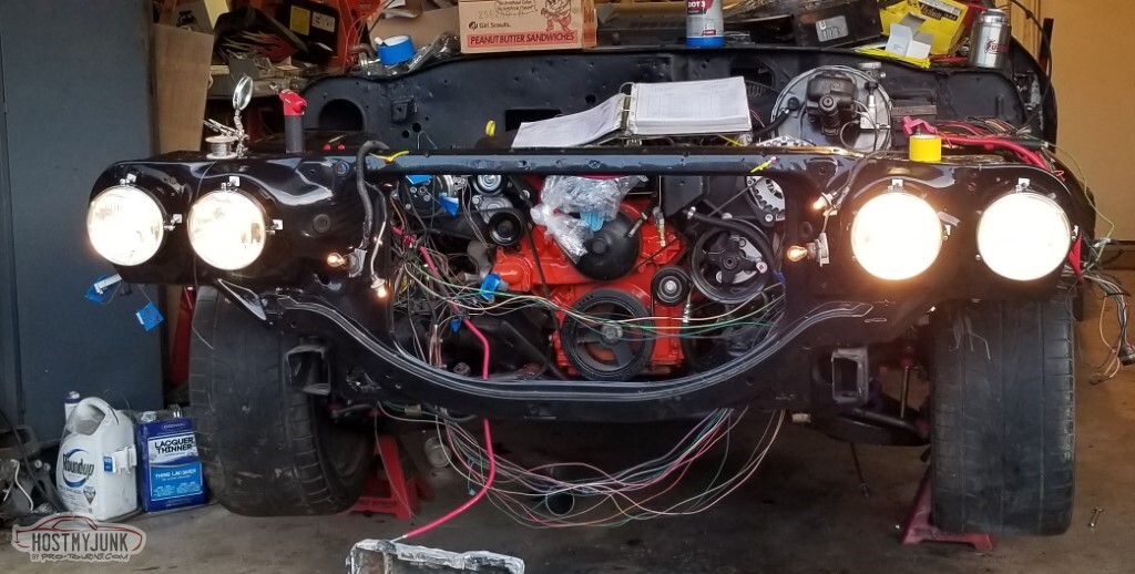
I have adapted the 60s headlight switch to the F-body harness. It works.
Conveniently enough, I had two damaged oxygen sensor connectors. Removed those, and put the other two as the "front" in the PCM.
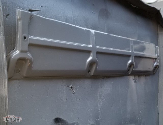
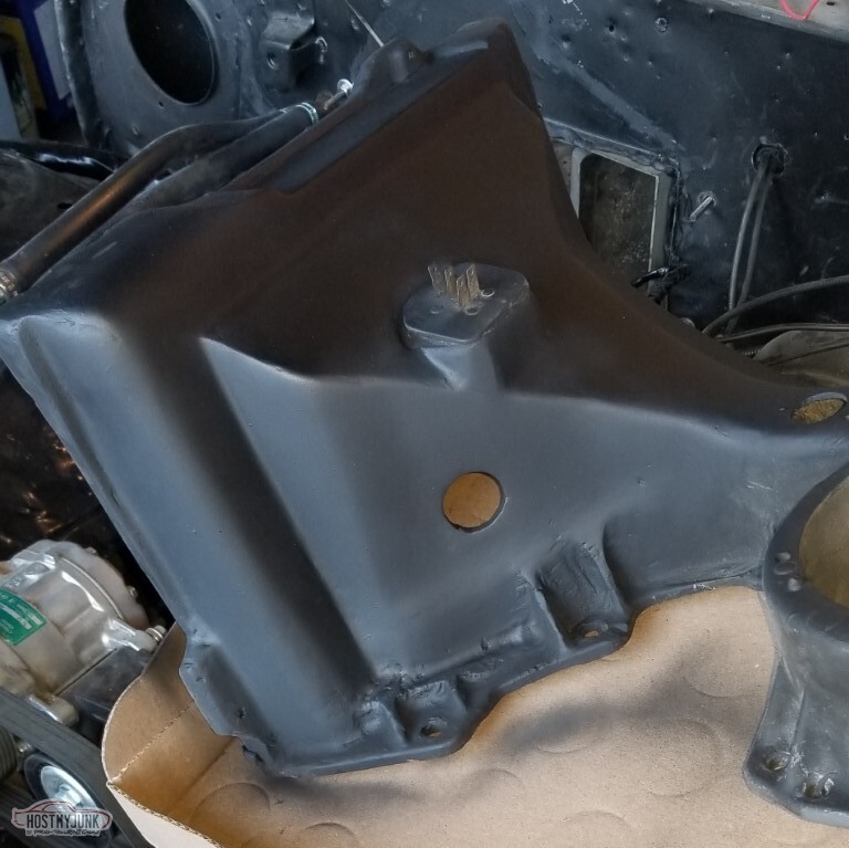
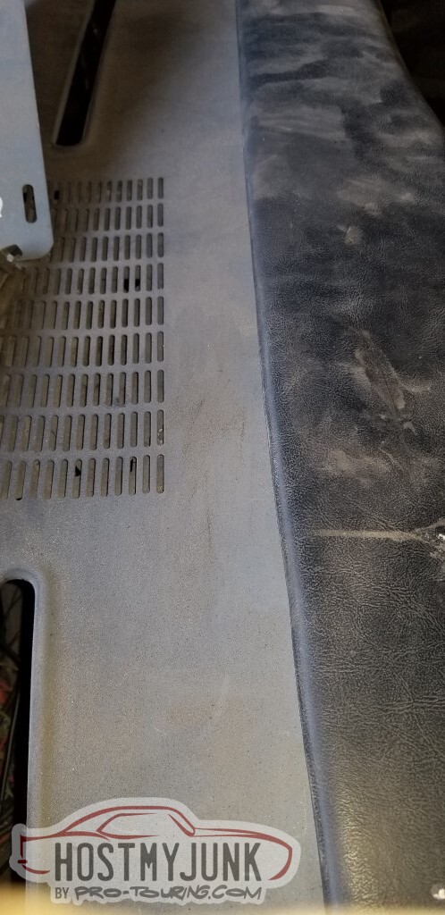
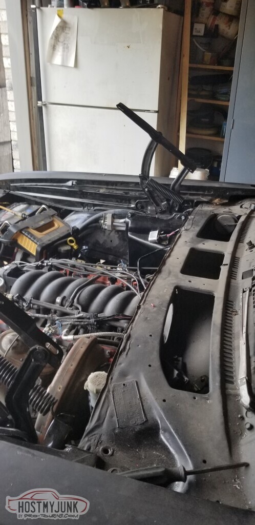
Radiator Support Cover (whatever the proper name is) cleaned up and primed.
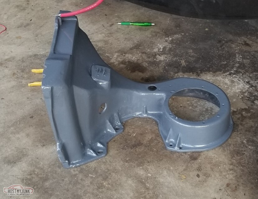
AC box also primed. It looked better in vaguely sanded bondo; I still have work to do here.
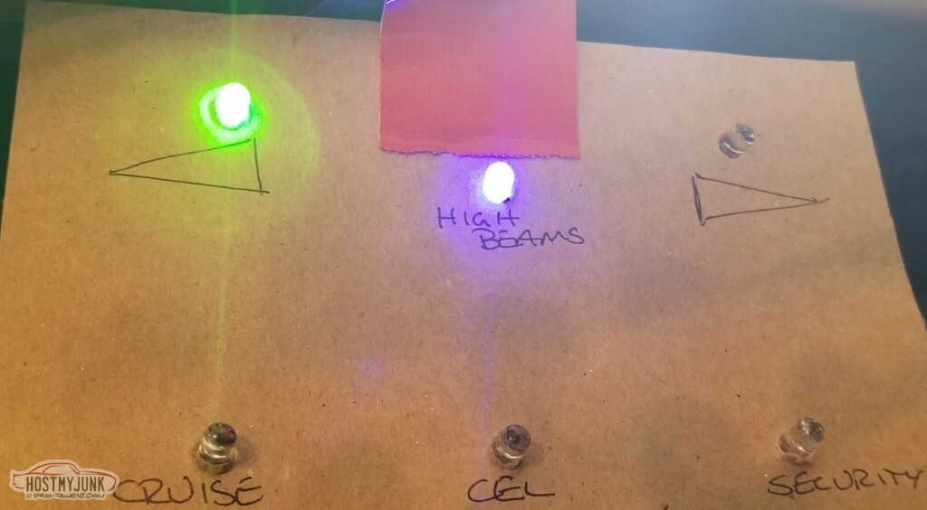
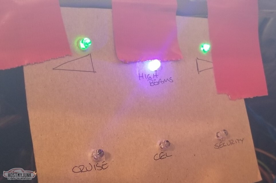
I made a fake dashboard out of cardboard. This is with the hazards on; note that (as mentioned), the right turn indicator isn't working.
 2005160020_tn.jpg"></a></td><td>
Added a clamp to hold wires away from the headers.
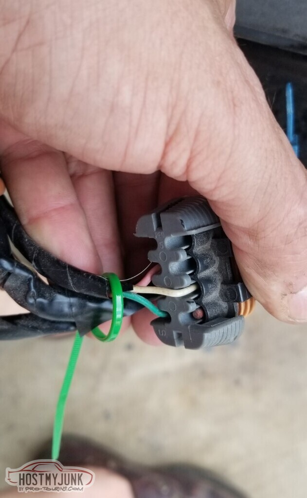
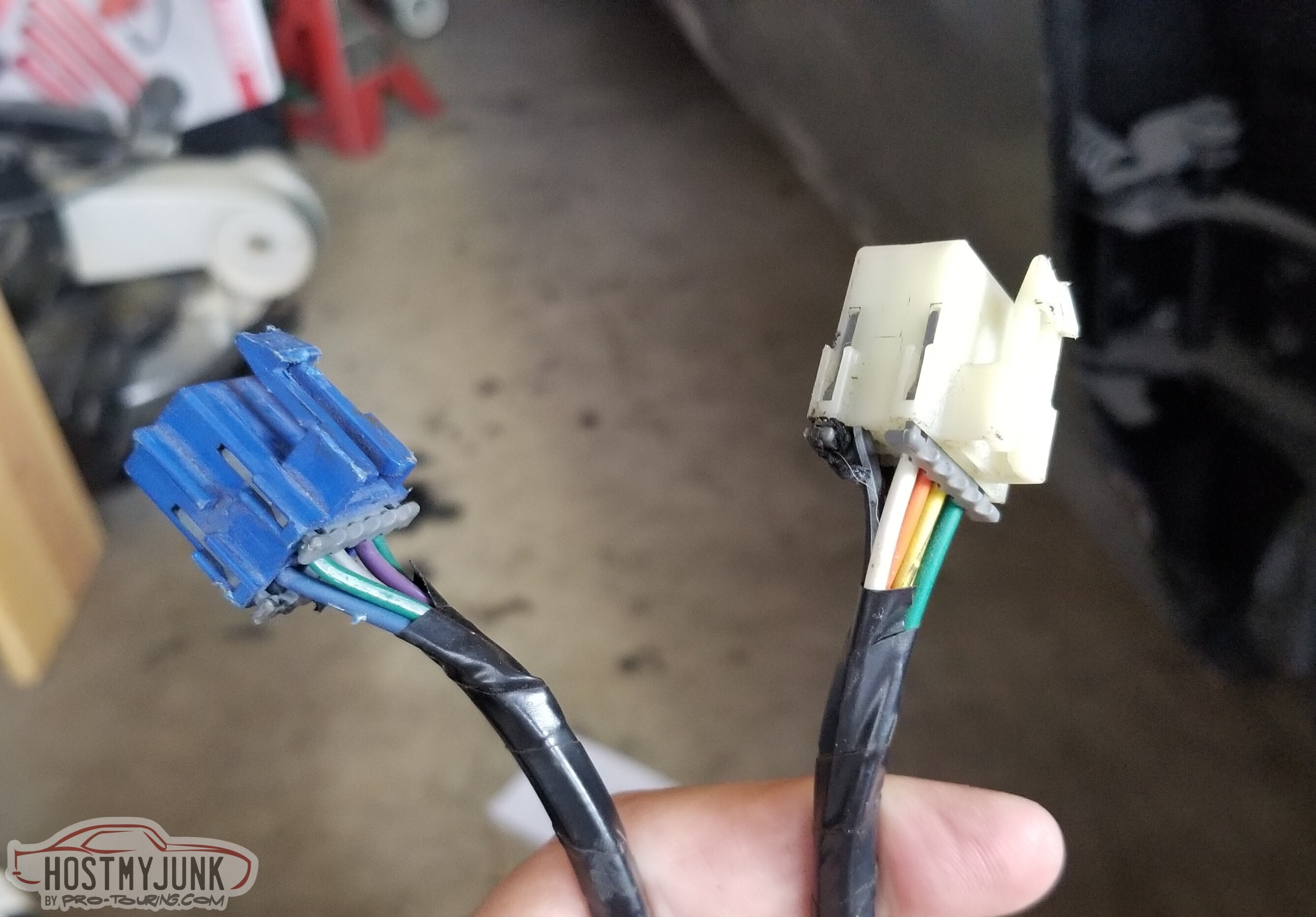
I got a new set of column connectors (well.. to be fair, I got three different ones).
Painless 30805 is a new connector with pigtails and was almost $50. That got returned.
American Autowire 510643 is a big kit with a bunch of connectors, one of which is this. I got it and haven't used it.
American Autowire 500428 is just the connectors here and was less than ten bucks.
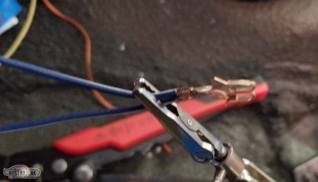
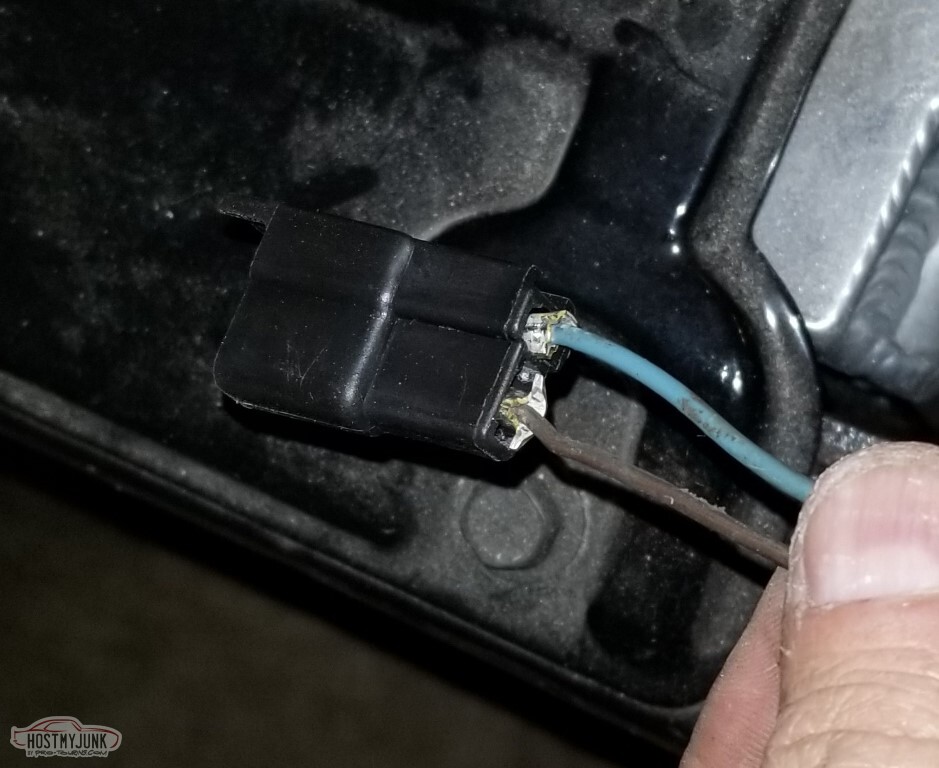
The connector opens up like this.
New connector crimped in place (also soldered, not seen here)
Also not seen here:
The Camaro F-body uses separate bulbs for brake and turn. That'd be.. unfortunate in this case, since my taillights only have one socket.
The Firebird, however, uses one filament for both stop and turn. The difference is a connection between C216 P and the brake light switch. ; Simple enough, since I have the connectors already.
And with that, my turn indicators work.
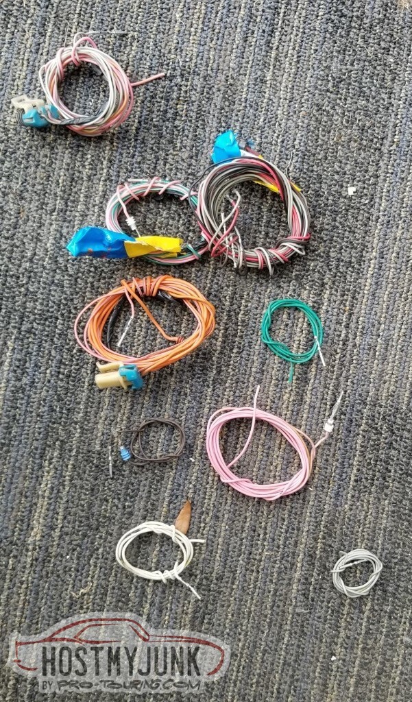
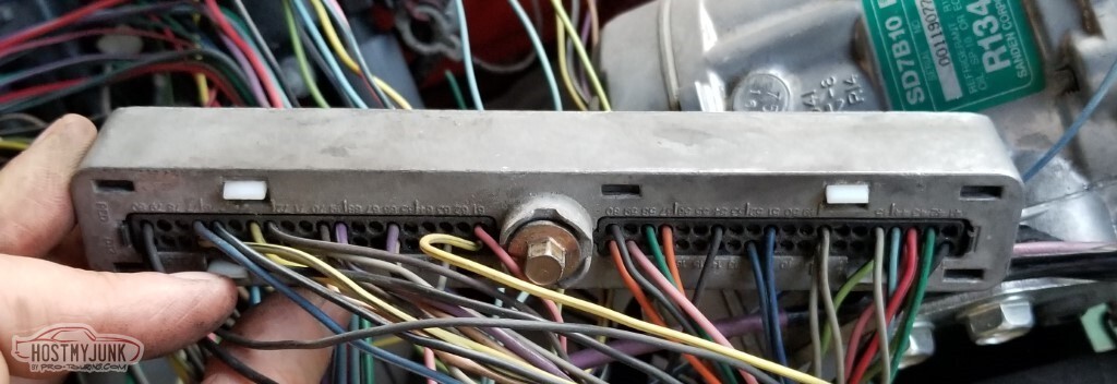
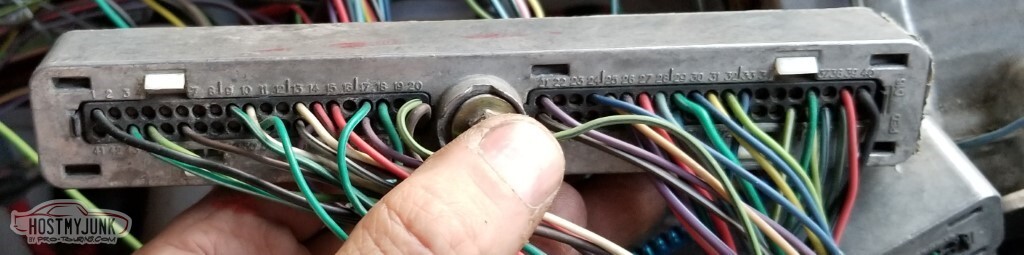
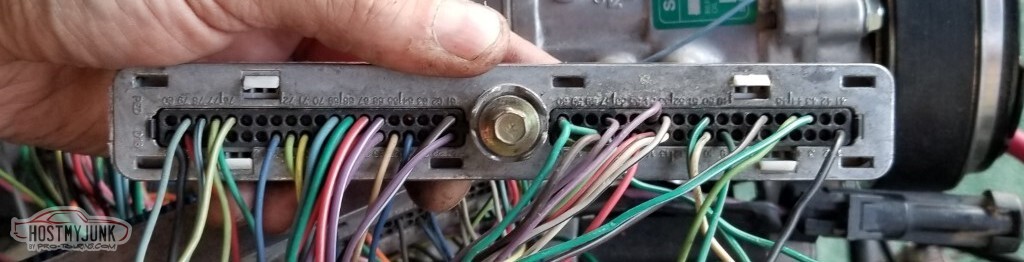
These pictures were mainly for me to keep track of what pins had and had not been removed.
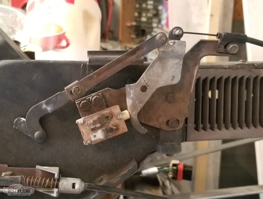
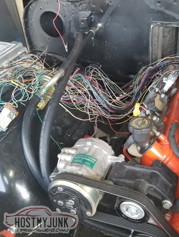
The stock 69 AC controls provide power to the compressor at all times when the mode switch isn't in "off", so long as this switch on the mixing box thing is happy.
My switch is not happy. At no point does it make contact.
So quite a bit of electronic contact cleaner later, and this switch conducts electricity when the lever is like this
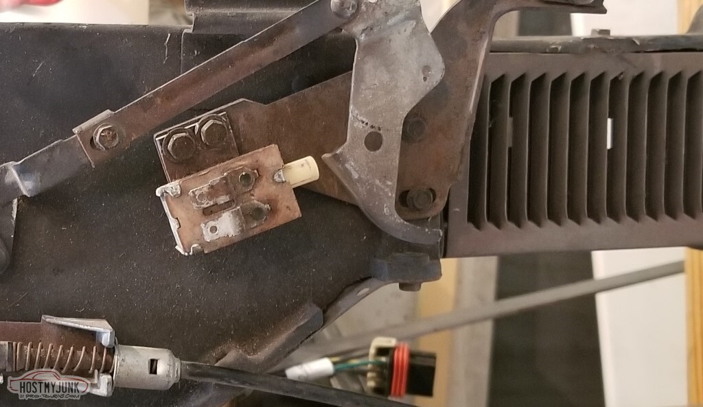
but shuts off when the lever is like this. That corresponds to the diverter door being closed - at this point, the incoming air is entirely what's come through the heater core.
Not pictured, because it wouldn't be easy to photograph and probably wouldn't make sense:
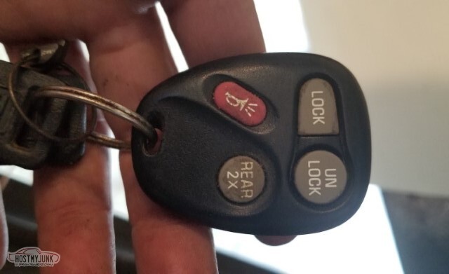
I bought some cheap (less than ten bucks for the set) power door lock solenoids from Amazon. With those, I was able to set up the key fob. It works.
Not pictured: Unlike the turn signals and the high beam indicator, the Security light is grounded via the BCM and gets power from the fuse box. With that configured, the security light on my cardboard dash turns on for a couple of seconds at key-on, then turns off.
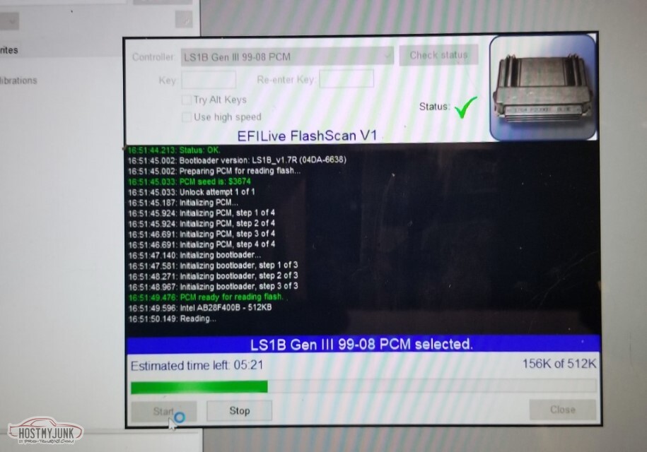
Time for the big test: Can I chat with the PCM?
Yes. Yes I can.
It's flaky, quite a bit of that is because of the really low output of this optima battery. With the charger cranked up, I can connect to it and pull the current data.
There's still some funkiness with key position and such but that may be power level, may be grounds... we'll see. This was a really good sign.
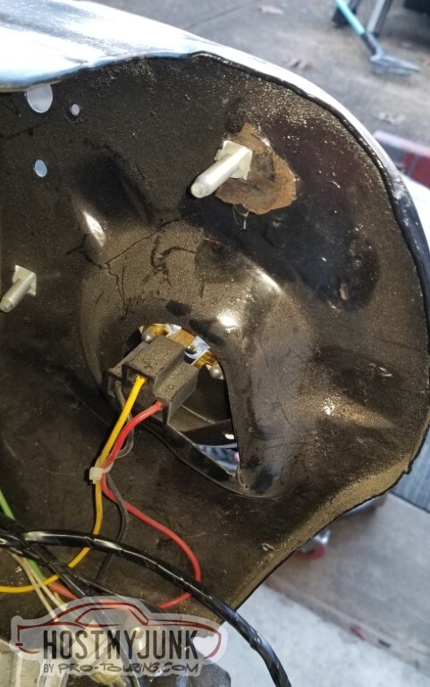
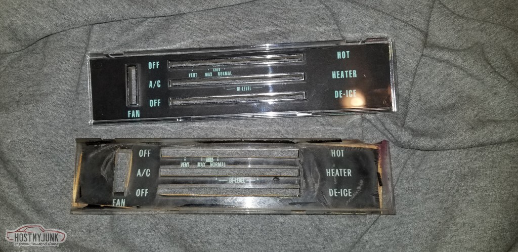
My stock controls have definitely seen better days. I got a new lens, but the lens is far from being the problem here.
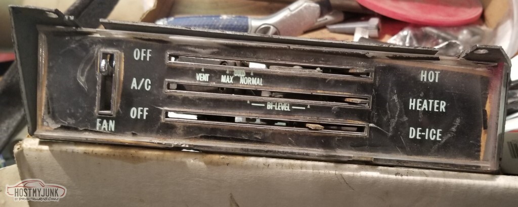
The backing is trashed and I haven't seen anyone talk about how one replaces this. I assume I'll mask off the chrome and paint it flat black?
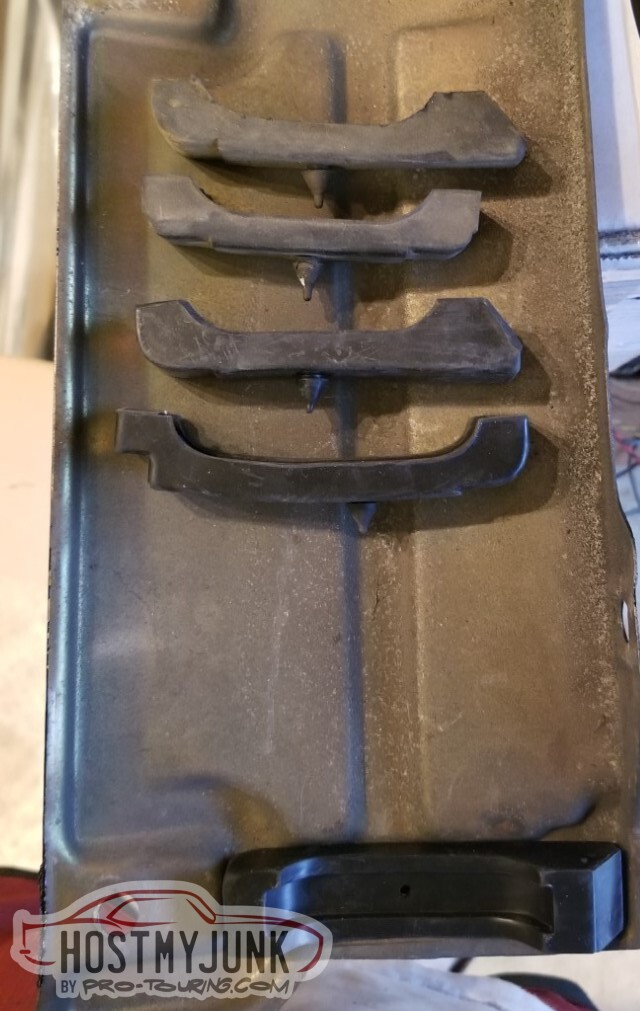
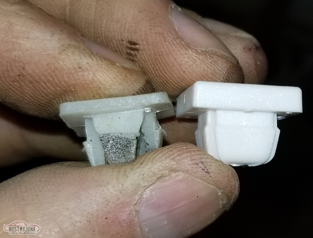
I have Had An Issue with the radiator cushions.
I bought a set of Nolathane for a 69 with a big block. They didn't fit (not pictured, I returned them). Not surprising, the BB wasn't original to the car.
So I bought a set of Nolathane for a 69 with a small block. They also didn't fit, and I returned those too.
The top two are old cushions from this radiator. The very top one is just like the third one down and the one I mounted. It fits. The second one down is my other original, and it's unlike the rest of these.
The Internet seems to think that the best route is to CUT THE CORE SUPPORT to fit the larger cushions. I am not to that point yet. I'll use my original small one in the other end of the upper here.
So what's next?
I have measured for the driveshaft.
I have ordered the hole saws I need to run the PCM wires through the firewall rather than through the windshield opening.
I will have to adjust the lengths of all these wires.
I - knowing that the fuel pump isn't hooked up yet - went ahead and tried turning the key to "Start". The engine did not spin over - but the starter did hum. Maybe that's a failed starter, maybe it's low power. Does tell me that the car is happy with the VATS I have.
Still need to run the wires to the rear lights, fuel pump, and fuel sender.
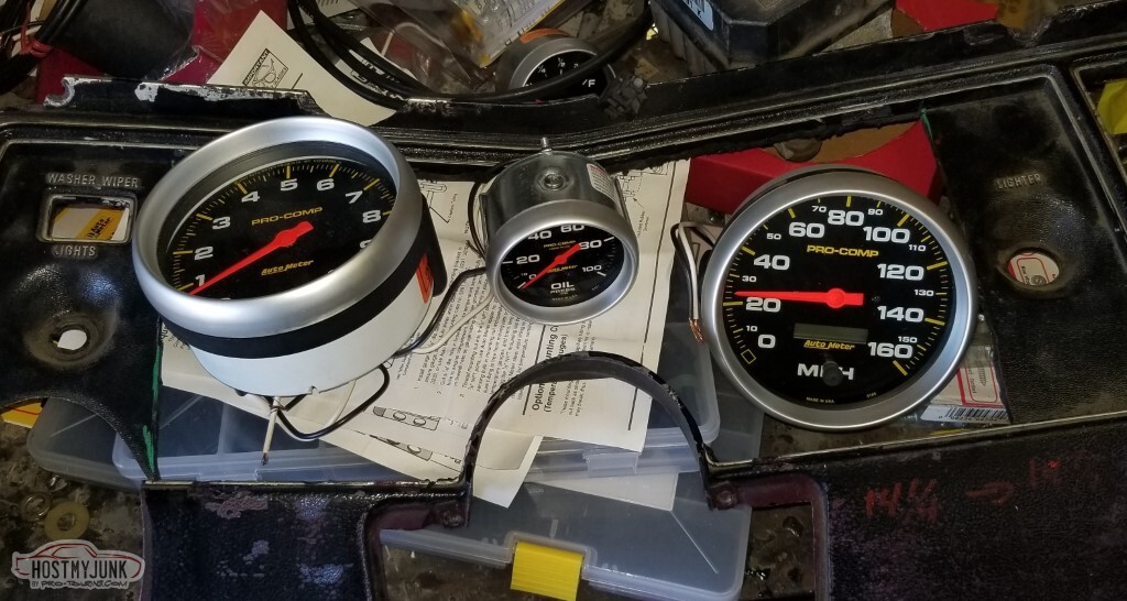
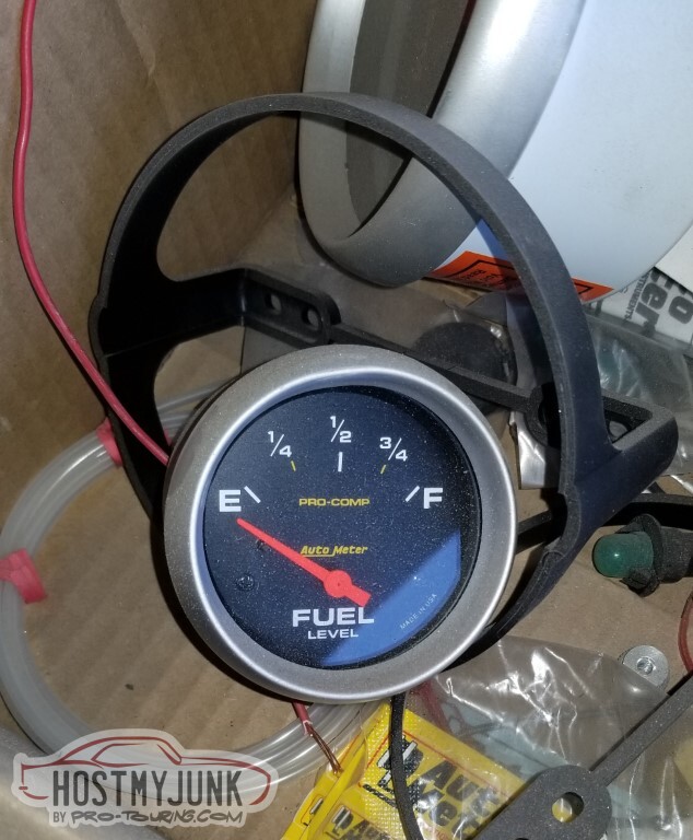
I have to do some planning on the dashboard layout; what I thought I was doing wasn't (apparently) correct. I don't want to drop $350 on a plastic custom dash to mount these autometer gauges and I certainly don't want to have that stamped steel gauge-holder under the dash this time. I've got two 5" and 3 2 5/8" to mount (Oil pressure, water temp, fuel level... maybe I should get a voltmeter too?).
-
05-15-2021 #82
-ɹoʇɐɹǝpoW-
- Join Date
- Jul 2002
- Location
- Mesquite, TX
- Posts
- 4,928
This is not such a documented-progress-post. Some doesn't need photos, some I just didn't think to take any. Electrical is hard to document forward progress.
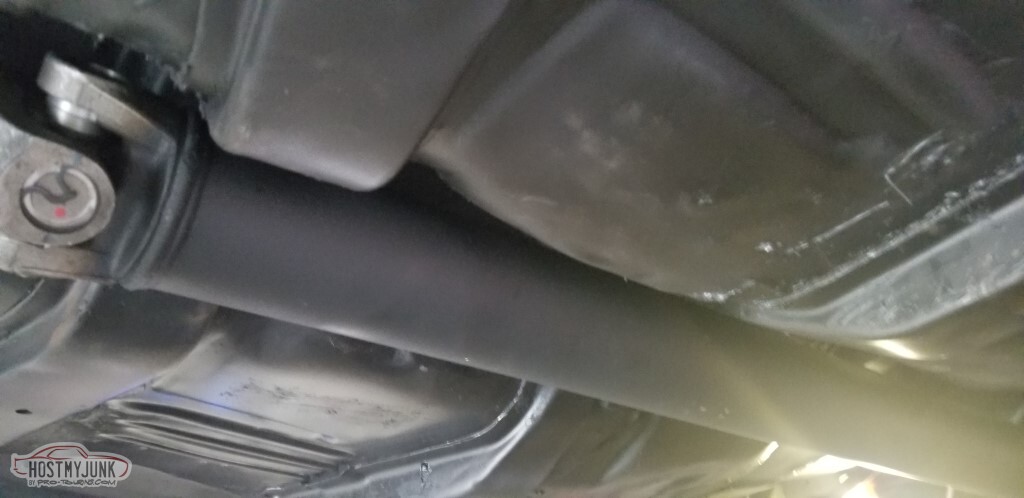
I got the driveshaft (3.5" with 1350 series u-joints front and rear) from a local shop.
Wires from ECU to interior (C220 and C230 plugs) have been run but the length may need attention and they definitely need wrapping.
The side mirrors - when I pick them from a junkyard - have about a 45 degree angle on the mounts (both sides).
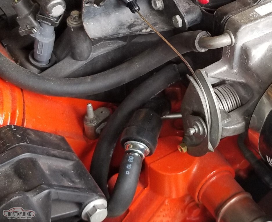
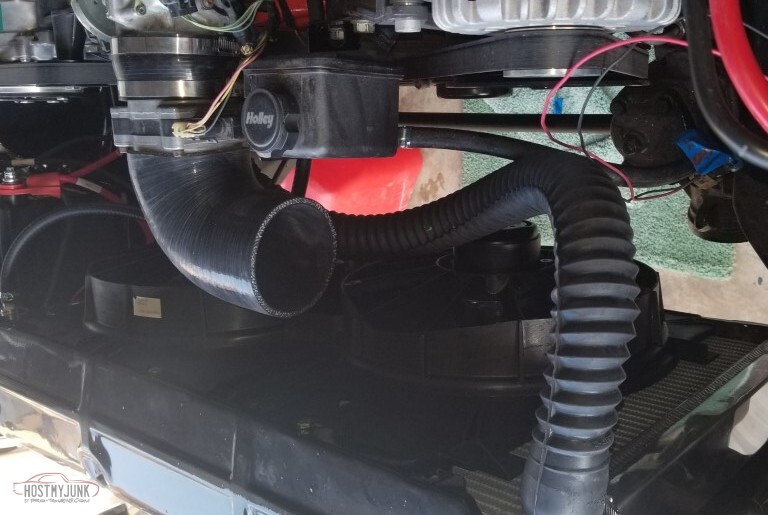
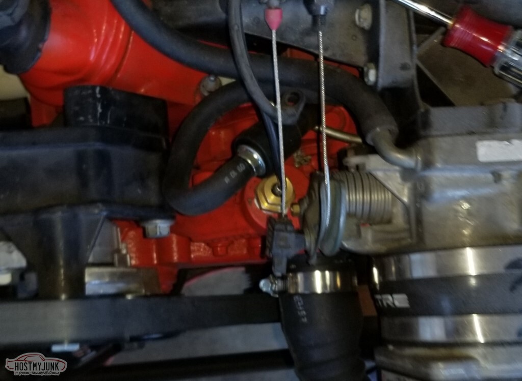
PCV hookup was a concern. I'd found suggestions on the web about converting to the LS6 valley pan that required cutting up the existing hose, etc. Good idea but only if you actually have the old hose.
This is Dorman 46036 for a 2000 Ford Expedition. It fits great.
Inside part of the AC box has been mounted.
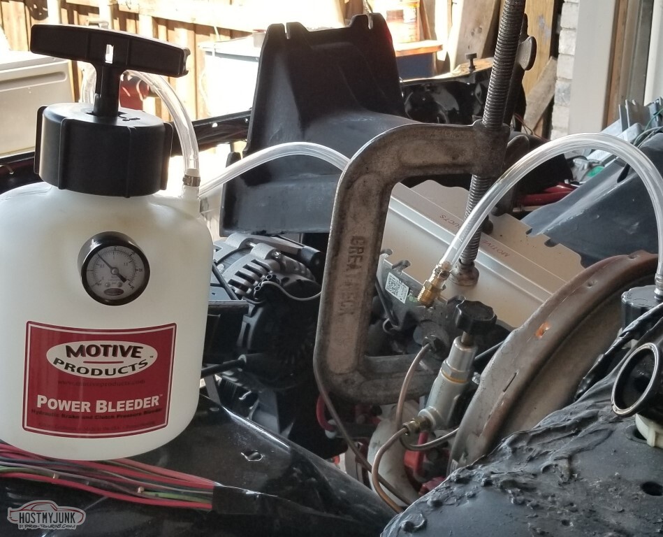
One-man bleeding of brakes and clutch.
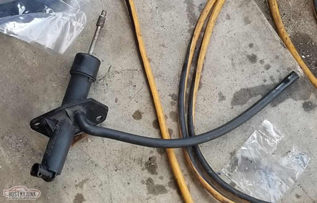
I am not convinced that the clutch is properly bled though; with that dual-disk McLeod clutch I had expected a much firmer pedal out of it.
Have confirmed that my brake leak has been corrected by replacing the caliper.
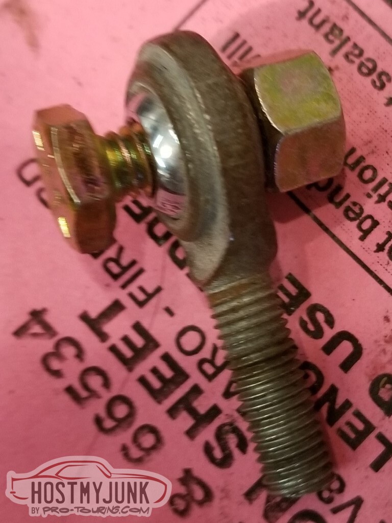
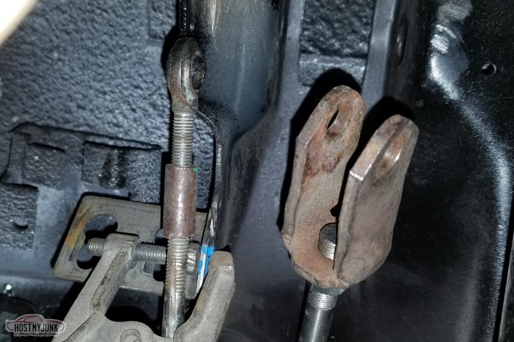
The clutch pedal sits (sat) far lower than the brake pedal. Also the through-hole was 1/4"; but the existing holes in the clutch pedal were 5/16".
I'd thought to try to find a rod end with a larger through-hole and longer threaded shaft. I failed.
Instead, I found directions that specified making my own 1/4 hole in the pedal arm, so I did that. I also adjusted the brake pedal to be much lower.
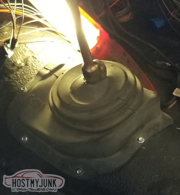
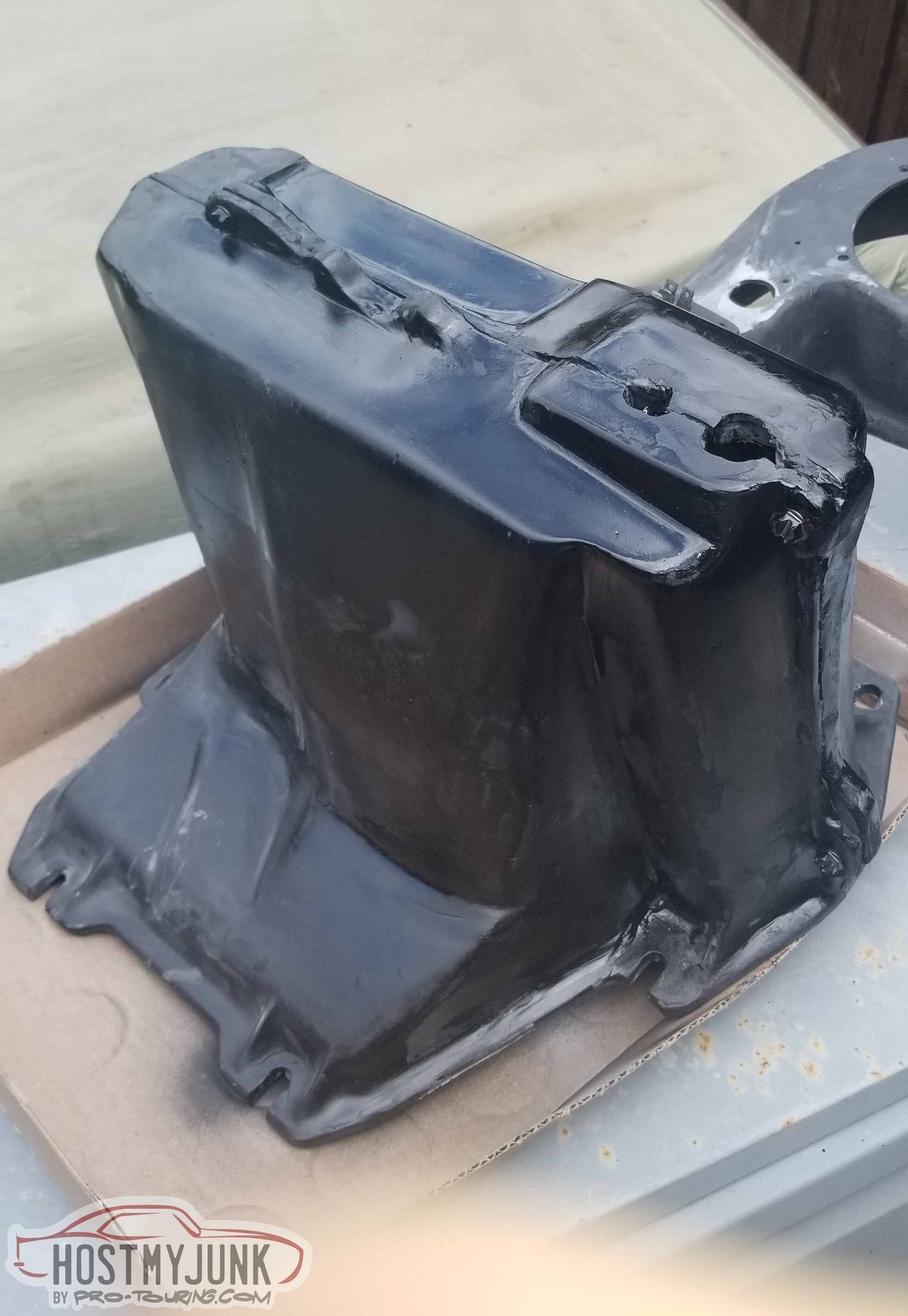
With the driveshaft in, no reason to not fill the transmission and put the cover on.
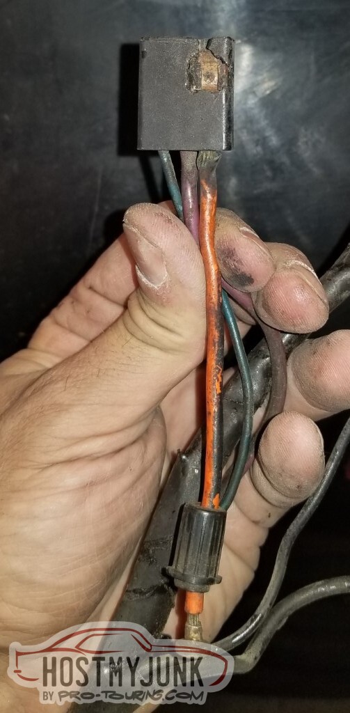
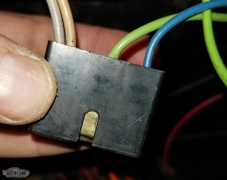
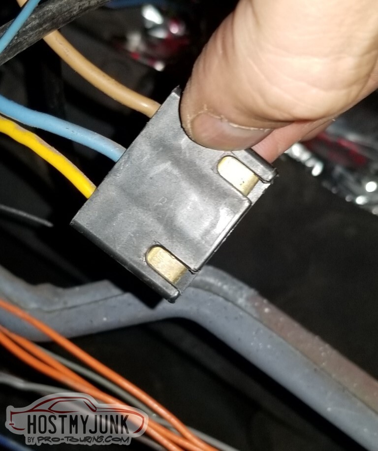
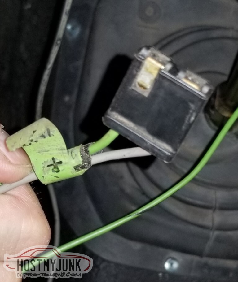
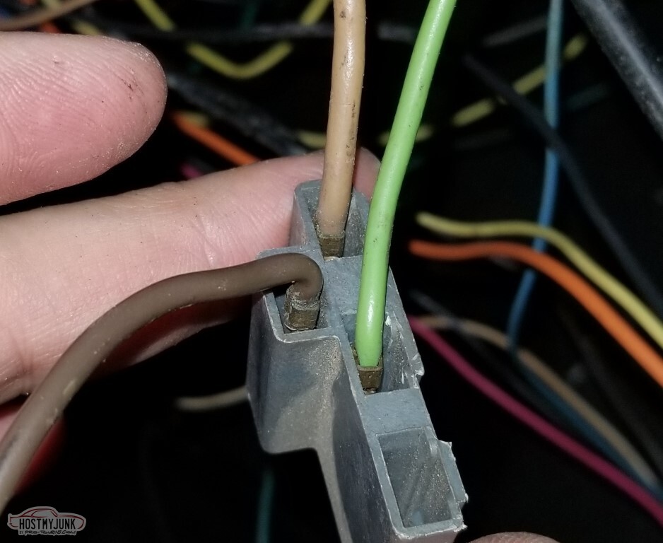
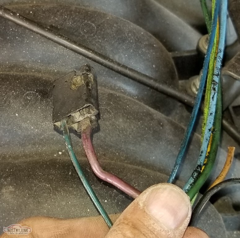
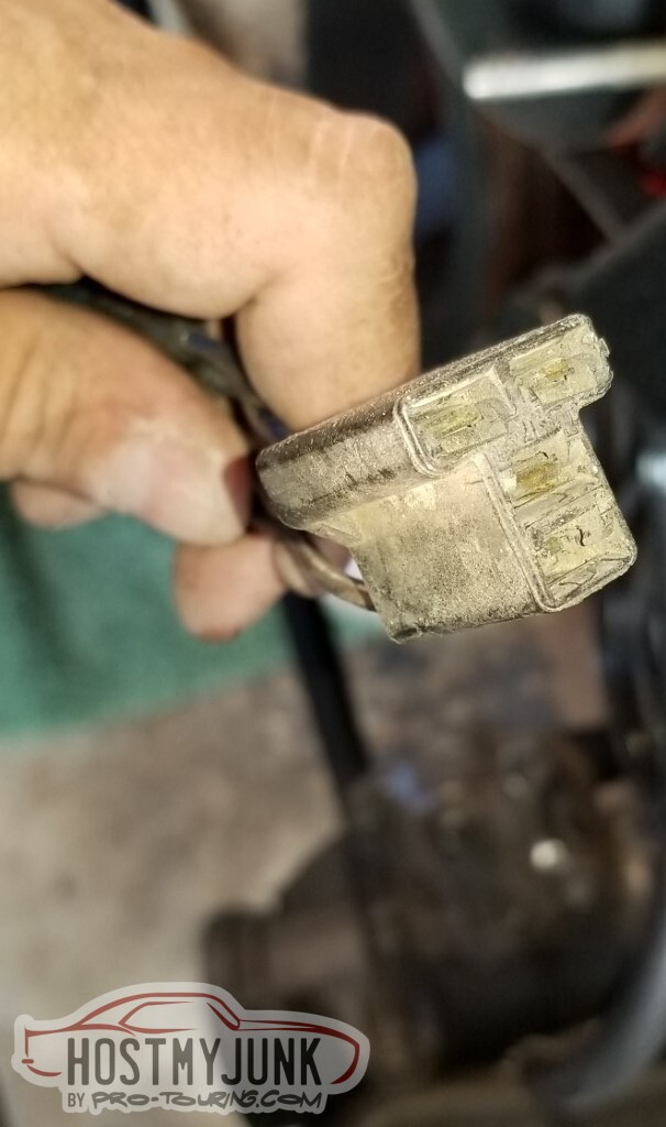
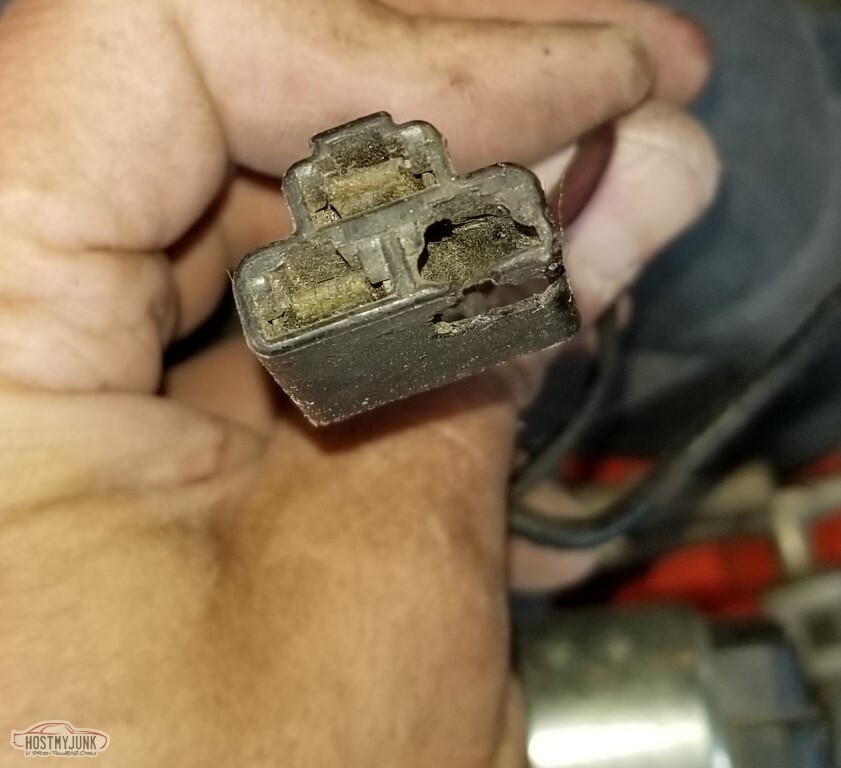
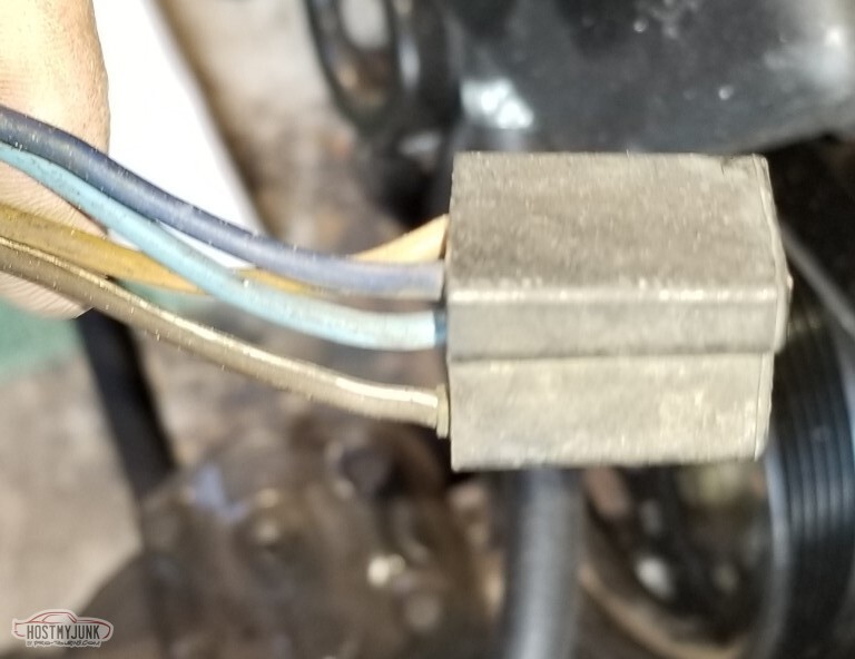
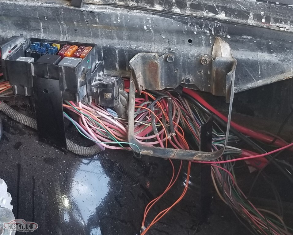
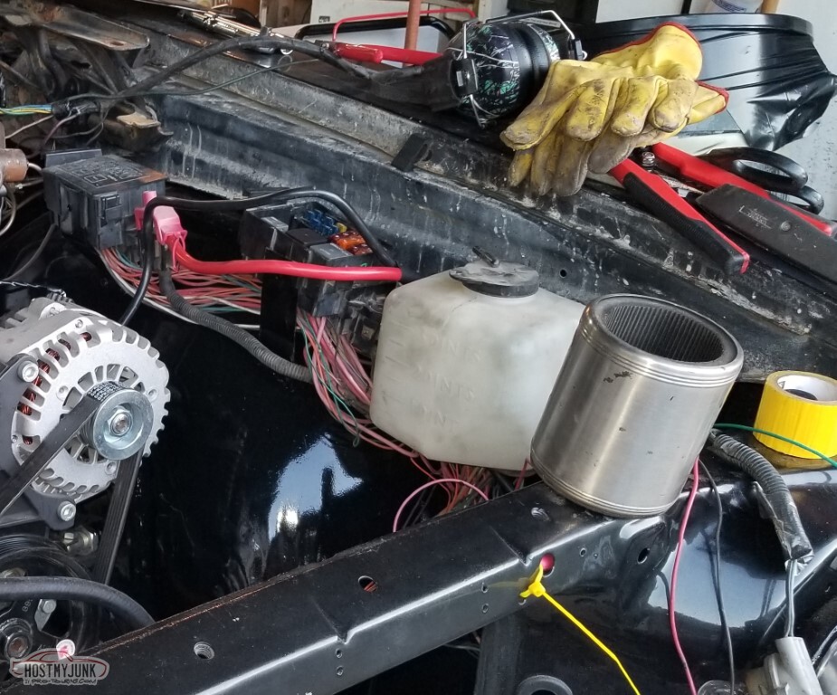
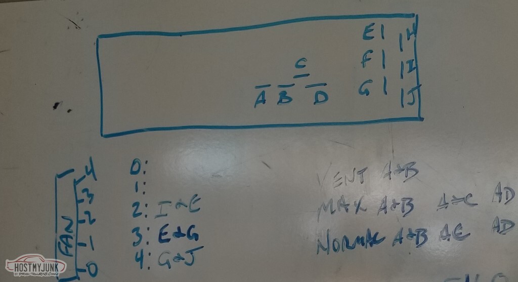
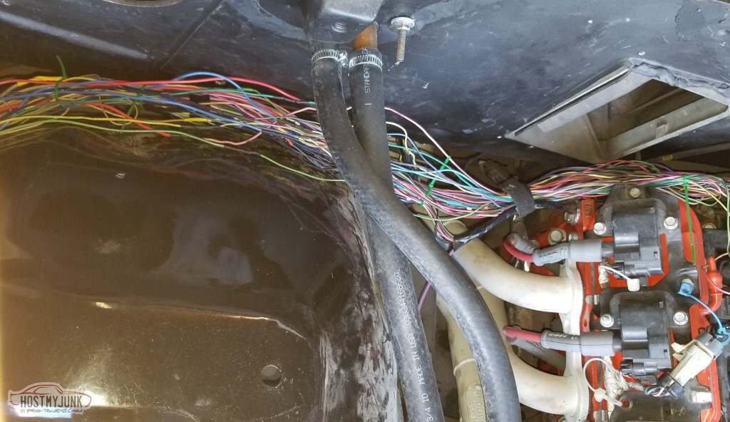
I'm using most of the 50 year old AC/Heater controls. I need to update my wiring diagrams to match.
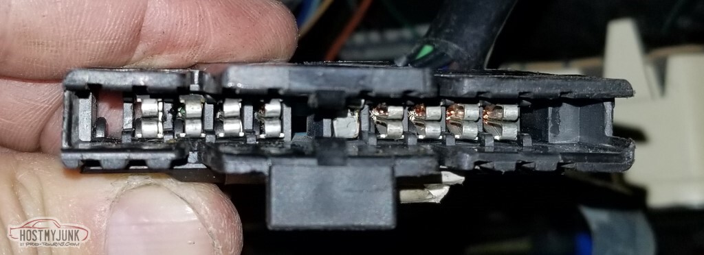
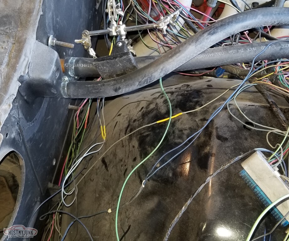
The orange relay feed wire in the first pic is replaced by the red wire from the Camaro blower relay. The brown wire in the sixth pic (four pin connector with only three pins) is the power feed for the whole assembly; it connects to the equivalent Camaro brown wire.
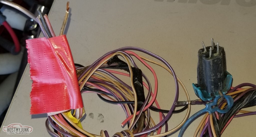
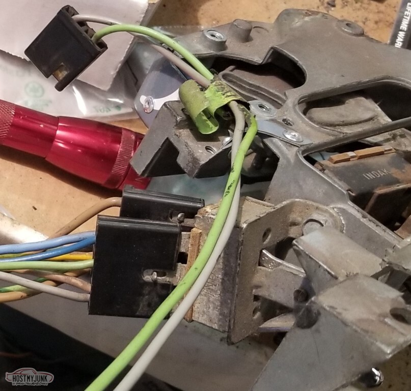
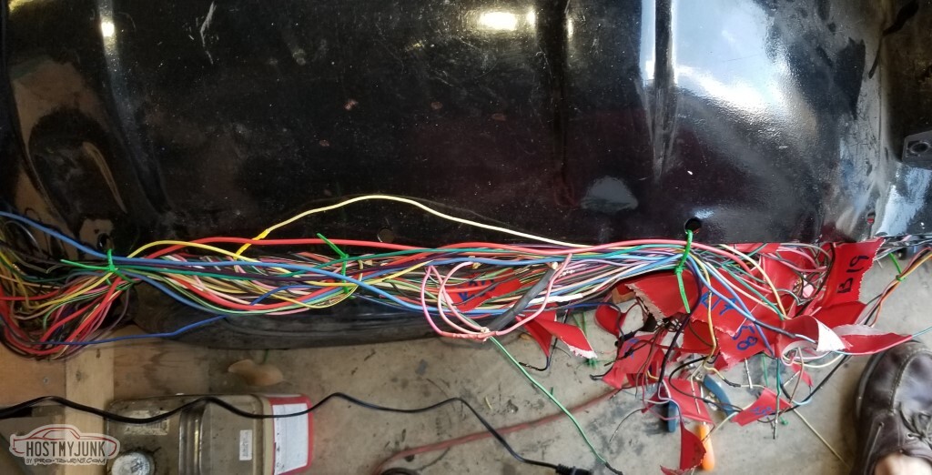
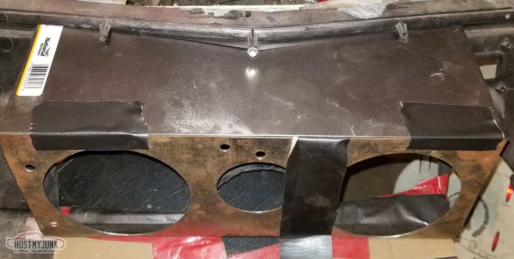
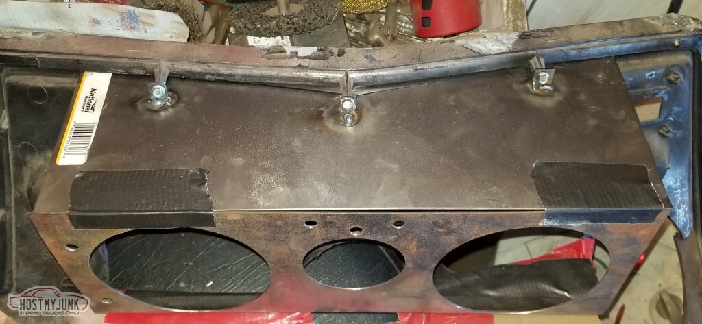
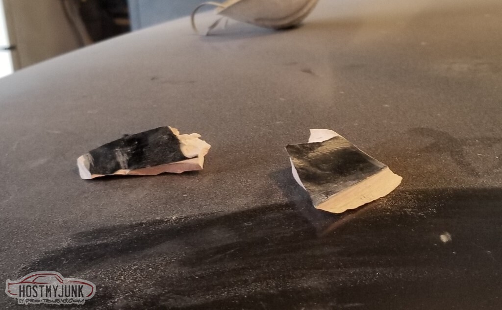
When I wire up a quick-disconnect for the dashboard, these are the inputs I need.
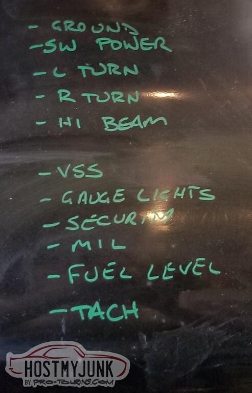
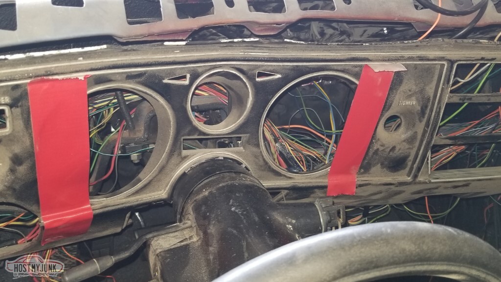
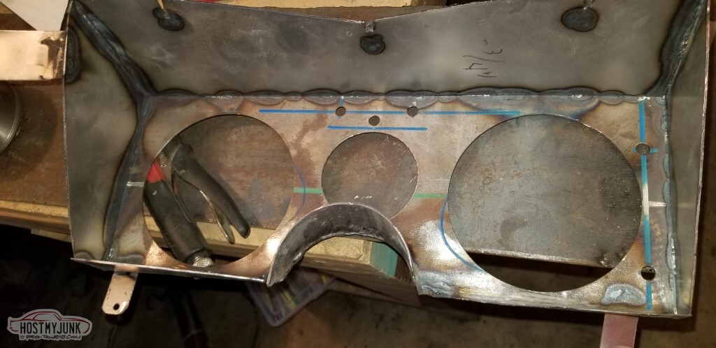
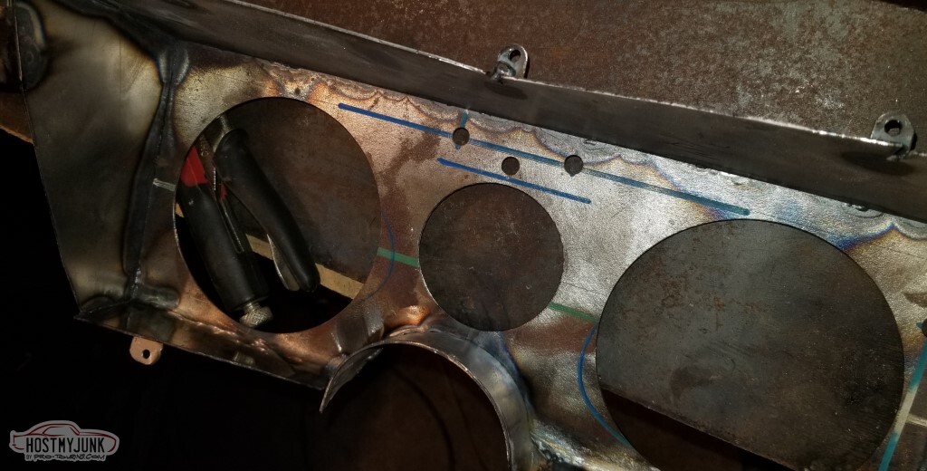
I will be cutting up my existing dashboard and creating a metal insert. Cuts go at the outboard edges of the red tape. Hopefully I won't end up regretting this.
I did go ahead and pick up a volt gauge.
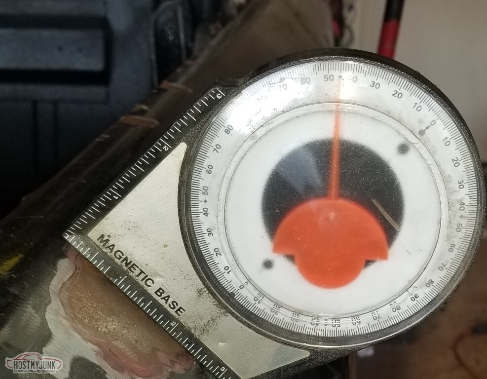
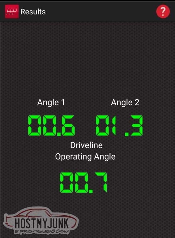
The Tremec app seems to be OK with my driveline angles.
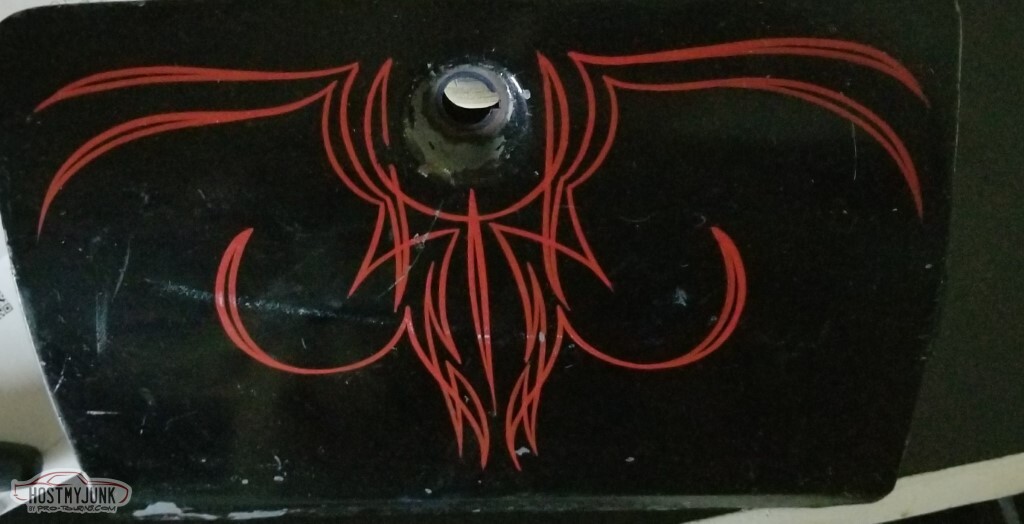
Finally got the broken glove box lock out. It's a shame to have to sand this down with that fancy pinstriping (from the 80s!) but it's not in good shape.
Also need to replace one of the mounting studs (#10-24, it appears).
(no pic): I bought a battery, and then had to go buy some extended-length side mount battery bolts.
All this, however, pales in comparison to the big news:
With the new battery the car cranks over just fine with the key, and also I can very quickly connect to the PCM with EFILive.
The fuel pump relay doesn't energize, which requires troubleshooting still.
If I manually trigger the relay I get up to the appropriate 58psi of pressure (and get a fuel leak, which I have corrected)
With fuel pressure and this new battery, it still spun with the key but did not try to fire.
One Crank Relearn later, it tried to fire.
And then succeeded.
It did not run well - open headers and I suspect one or more of the injectors has gummed up over the past fifteen years, and it's relearning everything - but it did run.
I tried to get a pic last time but couldn't get it to come out during the previous update - I'd wondered if I'd punched through the boss above the oil filter to mount the oil pressure line. The pic showed that apparently I had, the
fitting was threaded into it. Was it punched through though? Did not know.
Unrelated: I do have oil pressure. I know this because I did not put an oil pressure line on, and sprayed a lot of oil around. I need to add oil to the engine now, I bet I lost a quart.
Next up:- Hook up an oil pressure gauge
- Figure out the fuel pump issue
- Install cooling system
- Maybe build exhaust
- Maybe let it run a bit
- Finalize pedal positions and mount the various switches
-
05-15-2021 #83
-ɹoʇɐɹǝpoW-
- Join Date
- Jul 2002
- Location
- Mesquite, TX
- Posts
- 4,928
A lot of the progress isn't really "stuff that photographs well".
I put the driver's side fender on. I had previously mounted the cruise control box on the inner fender (you'd think I'd have taken a pic; I used rivnuts and everything, that's a thing that would have actually photographed well!). It interfered with the fender, so it had to get moved.
Also - probably more importantly - the mount for the forward fuse box interfered with the washer bottle mount (and, in theory, the washer bottle).
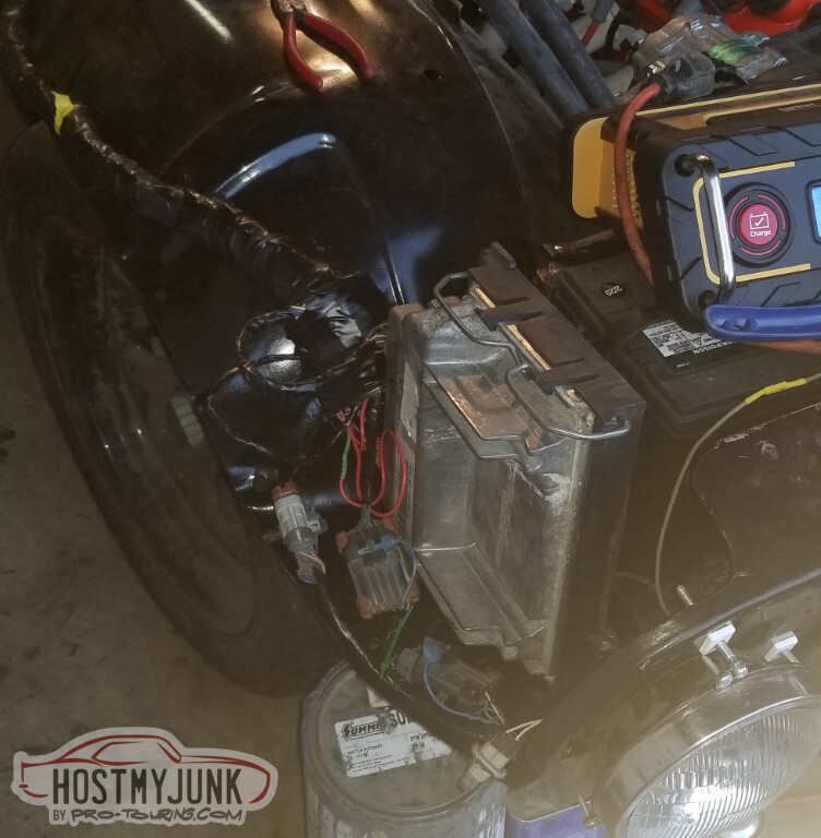
Pass side went on easier, and it looks like I can tuck the ECU up on the outer side of the battery (not quite sure if it's to be vertical or angled yet)
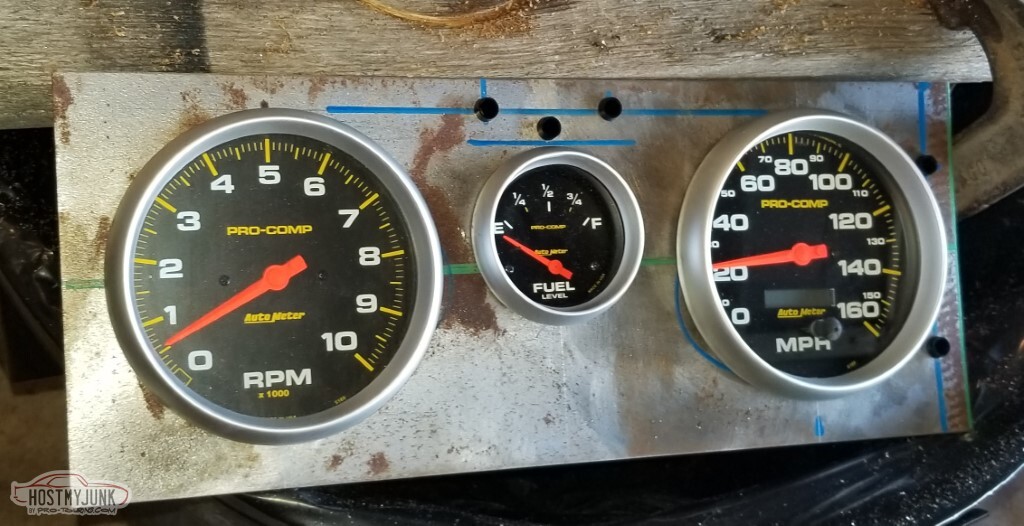
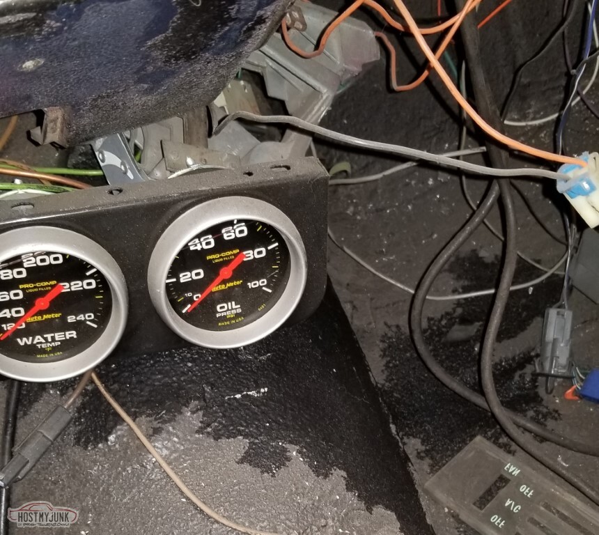
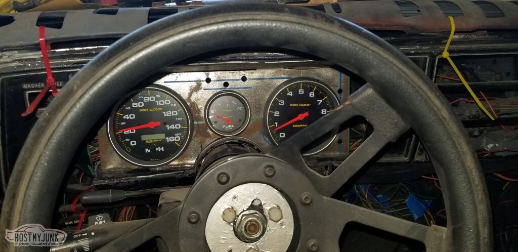
I had *thought* that I was going to be able to put the two large gauges plus the four smaller ones in the dash. I don't know why I thought that, there's just room for two large and maybe two small at most.
So I'm going to run the crappy three-gauge panel for oil pressure, water temp, and voltage; the main dash will have the two large gauges plus fuel level and the indicator lights from the cardboard panel.
Moved both fuse boxes towards the firewall (moved the forward one to the back). Now the washer bottle clears.
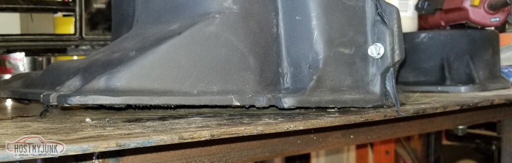
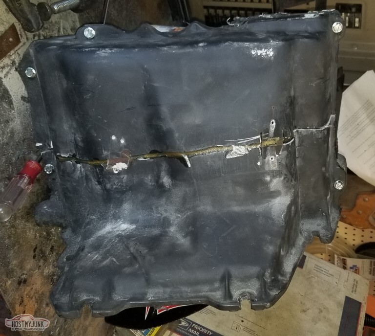
So I bolted the AC box together with the new coil and it promptly broke when I bolted it to the firewall.
I suppose that would explain it - the short side is about half an inch too
short.
Adjustment in progress.
Exhaust in progress too.
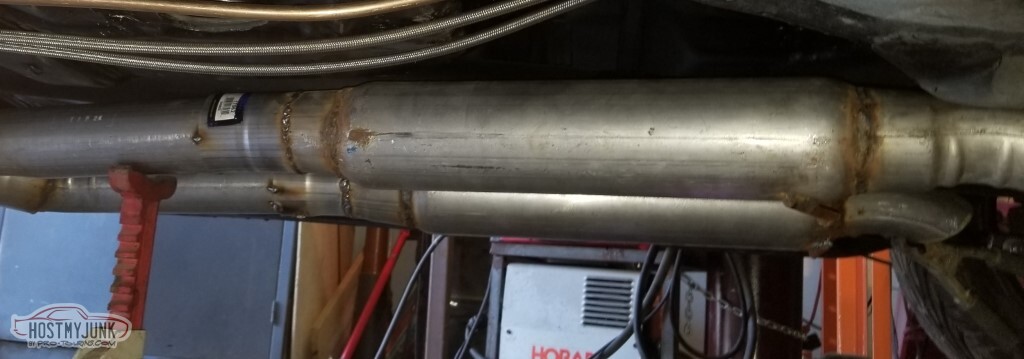
The exhaust is welded up.
As referenced in post #79 - this exhaust has got a reputation, so yes, this is really bad welds all around... but I didn't blow through so it *should* be leak-free.
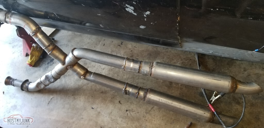
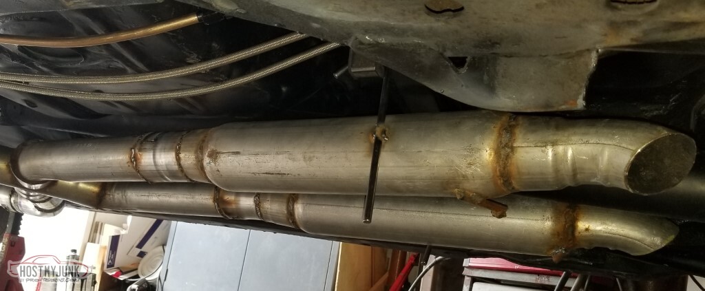
Mounted. Used the rivnut tool to mount the hangers.
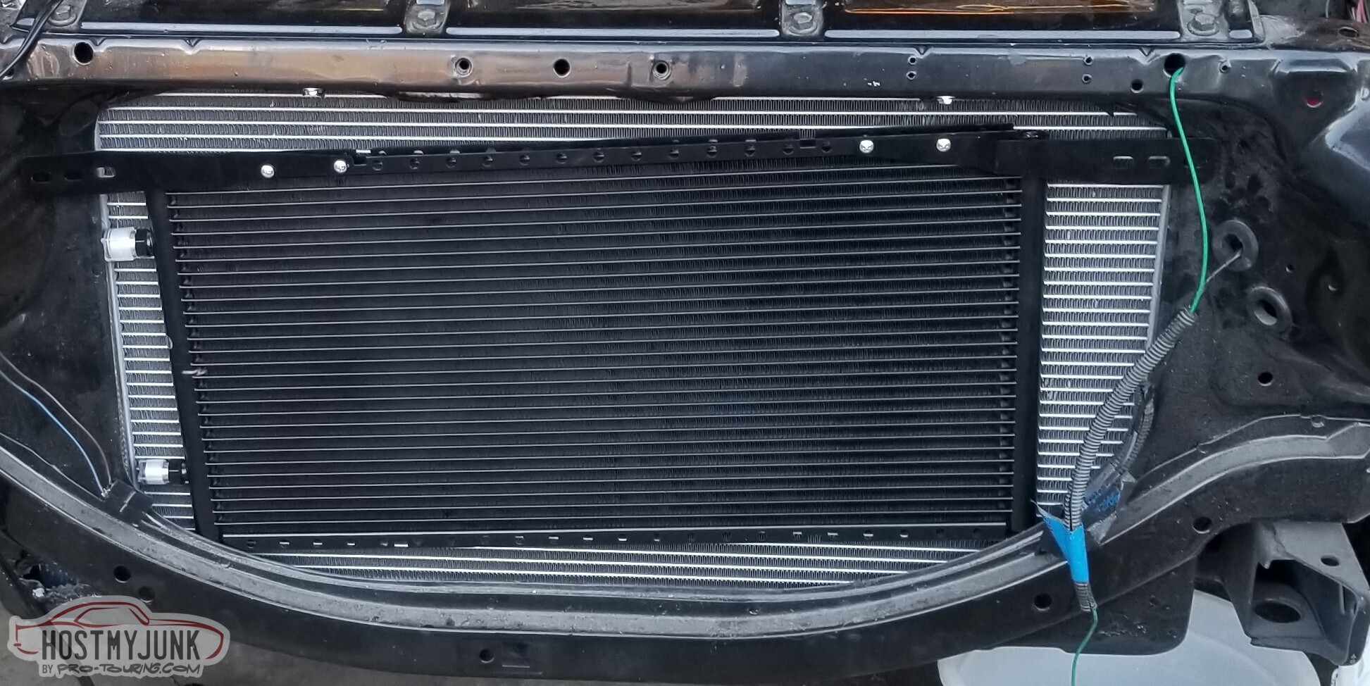
Tried a half-dozen different radiator hoses without finding one that really worked (O'Reillys will let you keep returning and ordering different ones but they get sick of it too) so instead I've just got the flexible universal ones. Suboptimal but it is what it is.
Also - not previously discussed - I had, a long time ago, bought a Lincoln Mark VIII fan as part of a group purchase on P-T. It was too large, and didn't really clear the water pump. Also the wiring for the Mk8 fan would be
a pain; I'd have to figure out how to turn the two fan inputs into high/low speeds here.
Easier option: bought an LS-era Camaro radiator fan setup. Maybe doesn't flow as much, but a lot easier to wire up and the size works pretty well. Rivnuts to mount, because when the only tool you have is a hammer....
Also added the correct heater hose, and filled the system with water.
So with the cooling system sorted, it's time to fire it up and validate the clutch works.
It doesn't.
It doesn't disengage, which means that when the car's running I can't put it in gear.
Replaced the clutch master (the old one was used?) and re-bled... and now the clutch works.
Still a lot softer than I expected but maybe that's correct?
The steam vent is hooked up, I drilled and tapped the water pump housing for the water temp sensor, and got a 3.5" bend for the intake tubing.
Oh - and not pictured at all - rear lights are wired up. The Type 56 connectors I'd used actually kinda suck - had to disconnect and reconnect a couple of times to get good conductivity; maybe that's me and maybe it's the connectors.
So: Clutch is up, cooling is up. Still need to lengthen the wires to the ECU and finish wrapping the wires with electrical tape. Need to replace the front tires, and then I will be able to take the car off the jackstands (which will make getting to the wires to wrap a bit easier).
-
05-15-2021 #84
-ɹoʇɐɹǝpoW-
- Join Date
- Jul 2002
- Location
- Mesquite, TX
- Posts
- 4,928
I bit the bullet and did the cuts for the main dash panel. I think I got a little in a hurry and the high beam indicator (top center) may not be perfect. If that's the case, I'm sure it'll drive me nuts for the next decade.
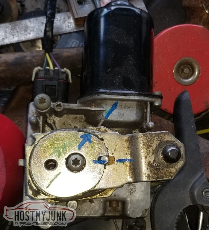
The 4th-gen Camaro wiper motor works, because why wouldn't it?
Marked where it "parks", then realized the whole thing was hitting the bolt at top left, and marked again.
I need to find out how long the stock EC wiper arm was so I can make this one pretend to be that long. If I could find the old arm, that'd be easier.
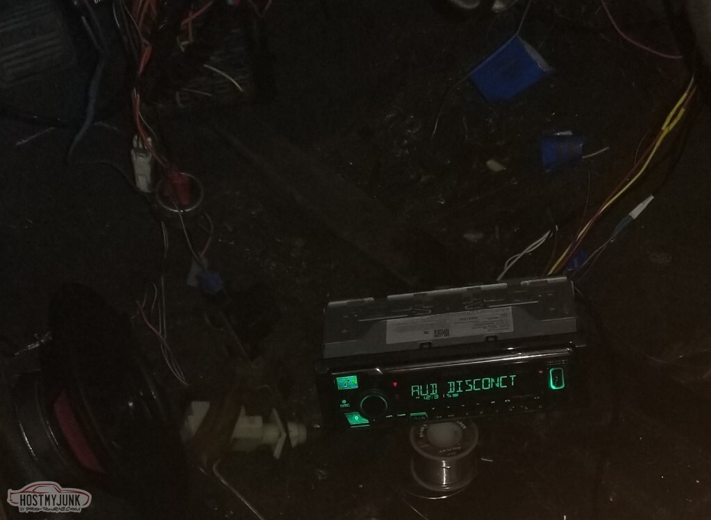
Got the radio and front speakers. I have a speaker box that I'm going to cut up to fit better, and in theory I have an amp for it but I don't know where it went when I tore the car down back in 2006! Where does the time go?
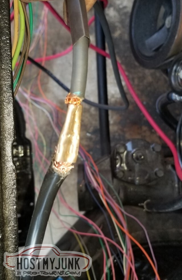
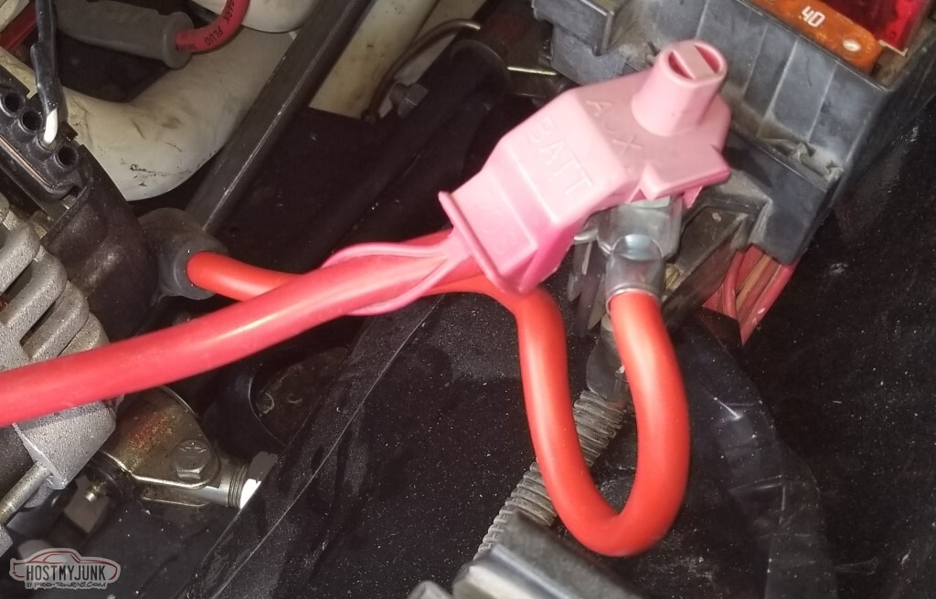
I did not understand why there were two large bore wires from the battery - one to the fuse box and one to the alternator... so I made it one large bore wire and a connector. This one is 12" and is really too long.
(Reference pic for the AC controls)
Current to-do list. At least the items get simpler.
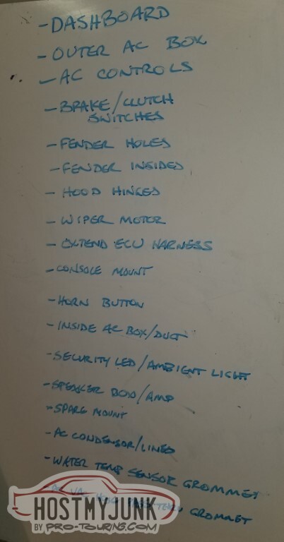
I bought a better sandblaster, or at least a bigger one.
I'd done my reading before purchase so expected to have to make some modifications, such as this one talking about updates to the pickup tube.</td></tr>
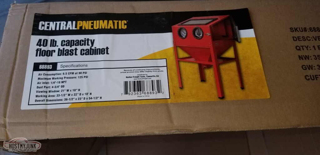
Yeah, that's not the pickup they supply anymore.
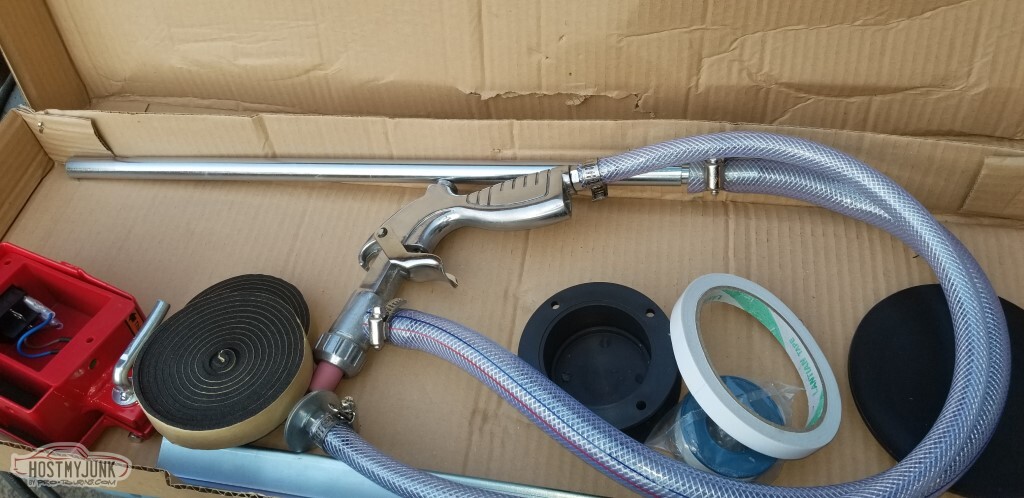
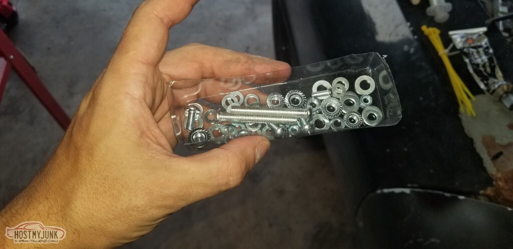
Also I'm short one M4x20 screw.
I have lots of spares though, just not an M4.
(not pictured) I went ahead and ordered the Skat pickup from TP Tools and yeah - this still sucks. I've apparently done something wrong as there's no sand flowing through, just air.
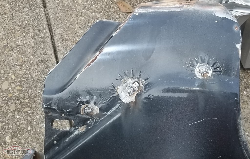
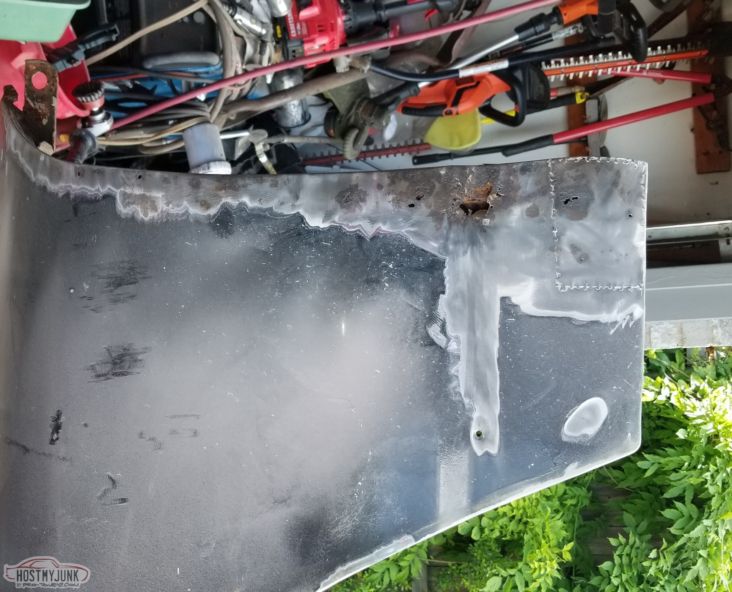
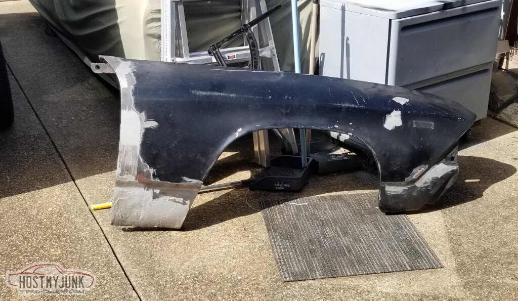
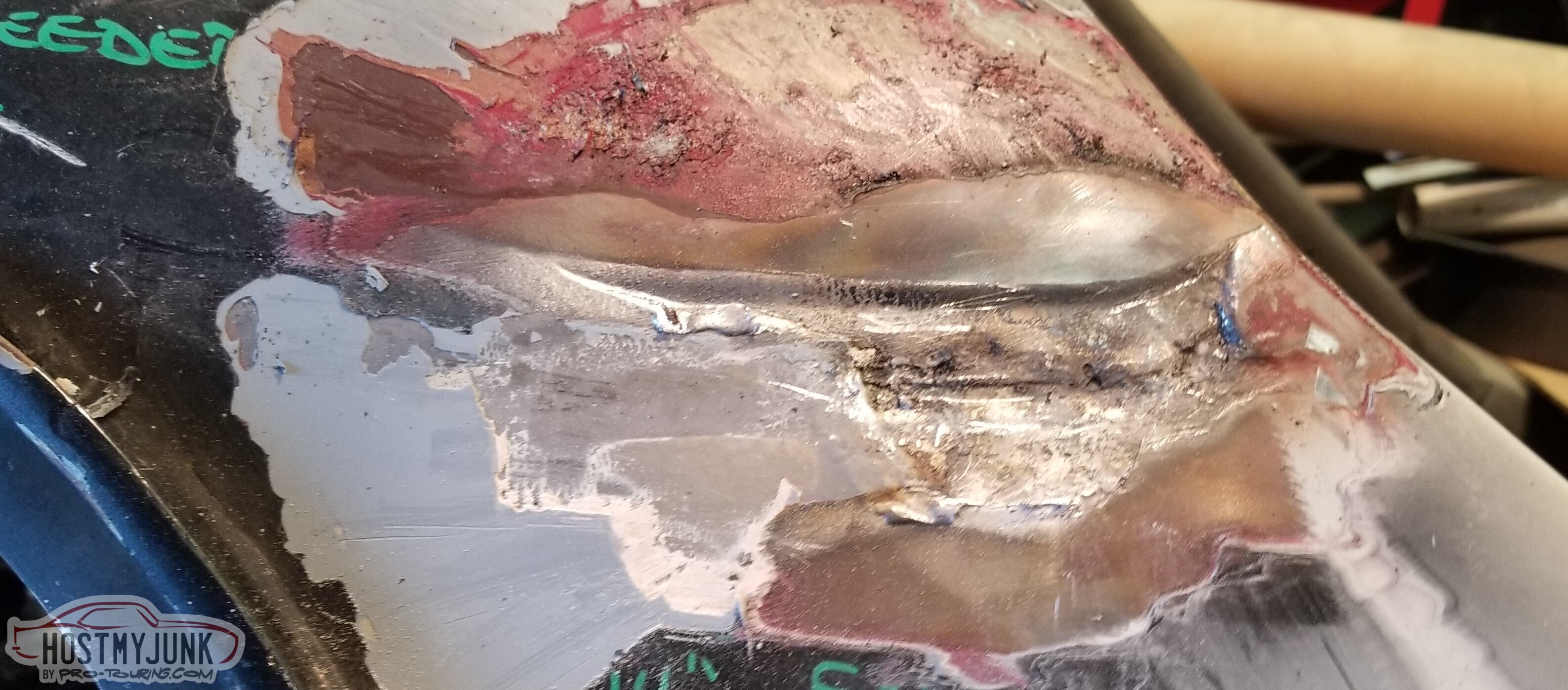
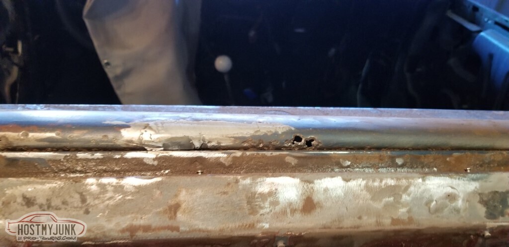
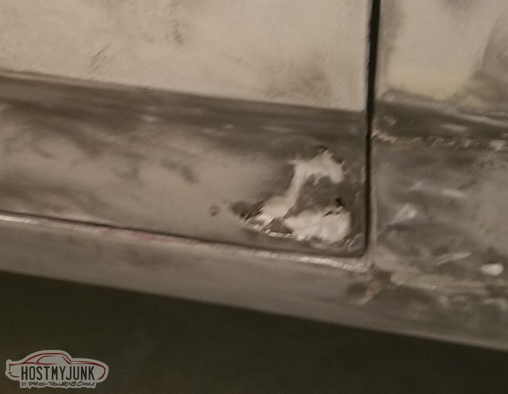
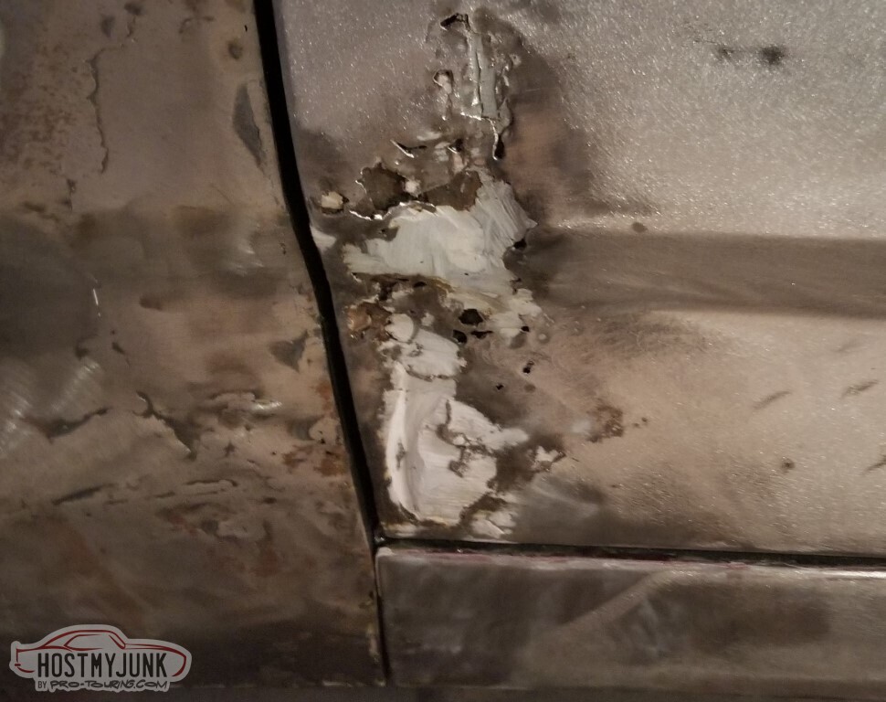
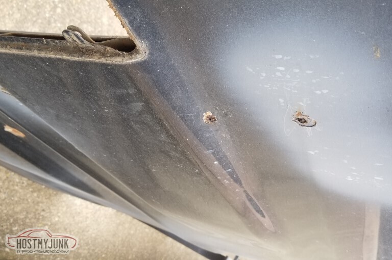
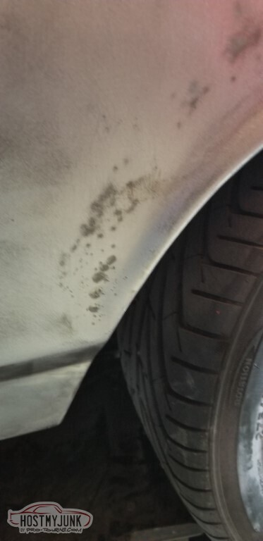
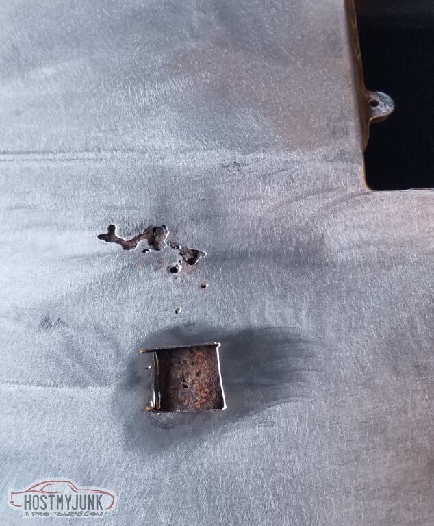
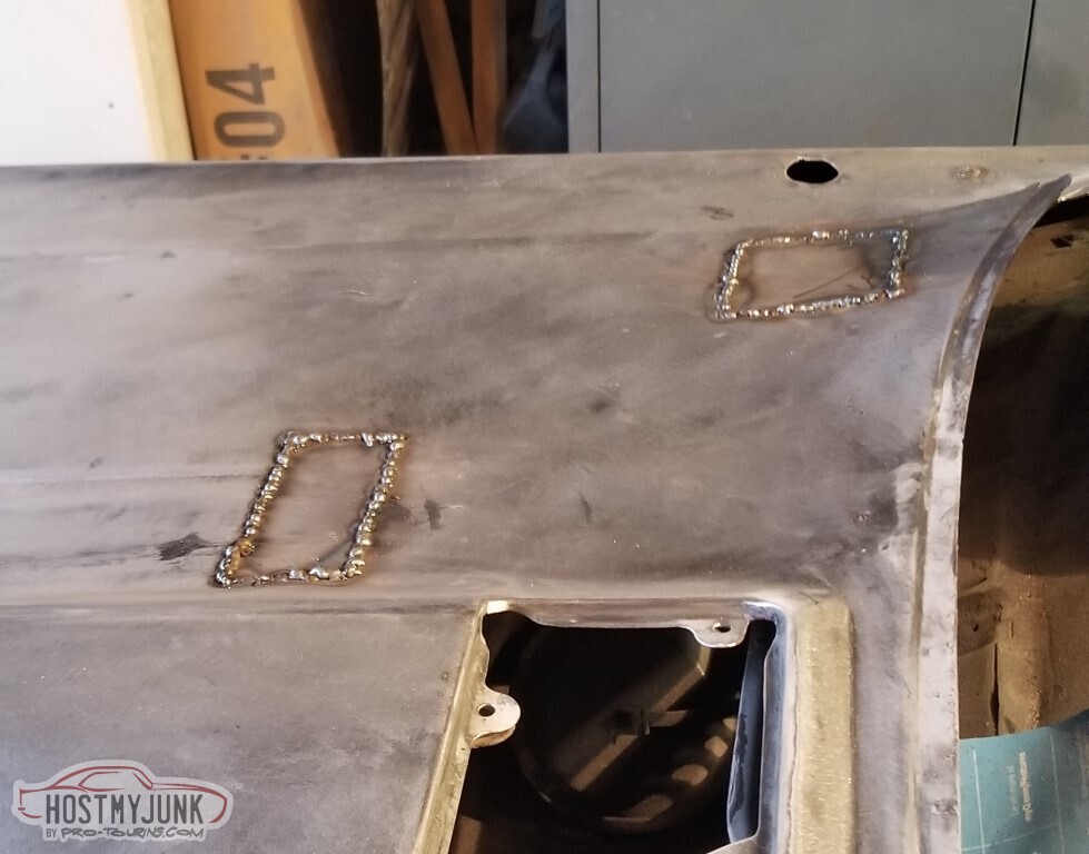
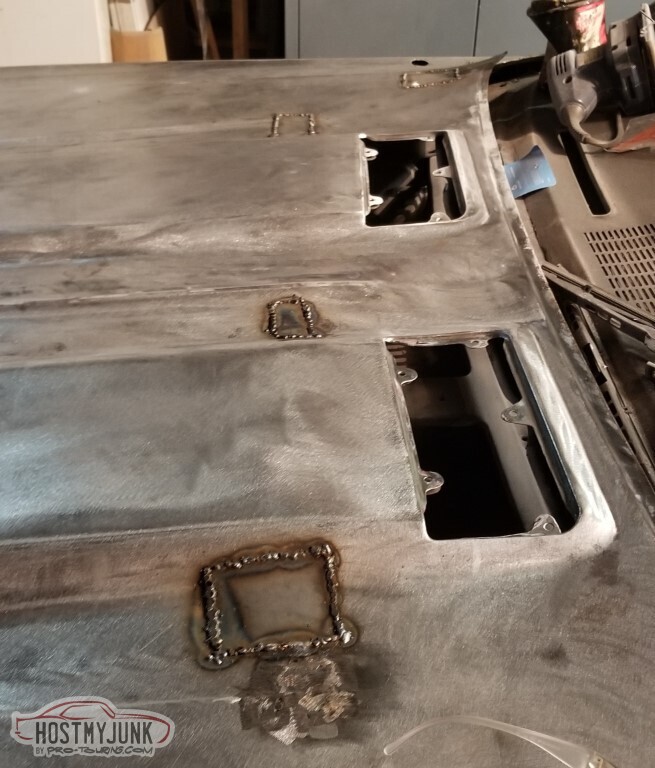
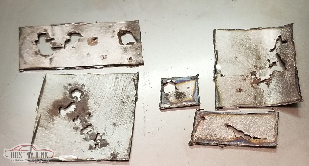
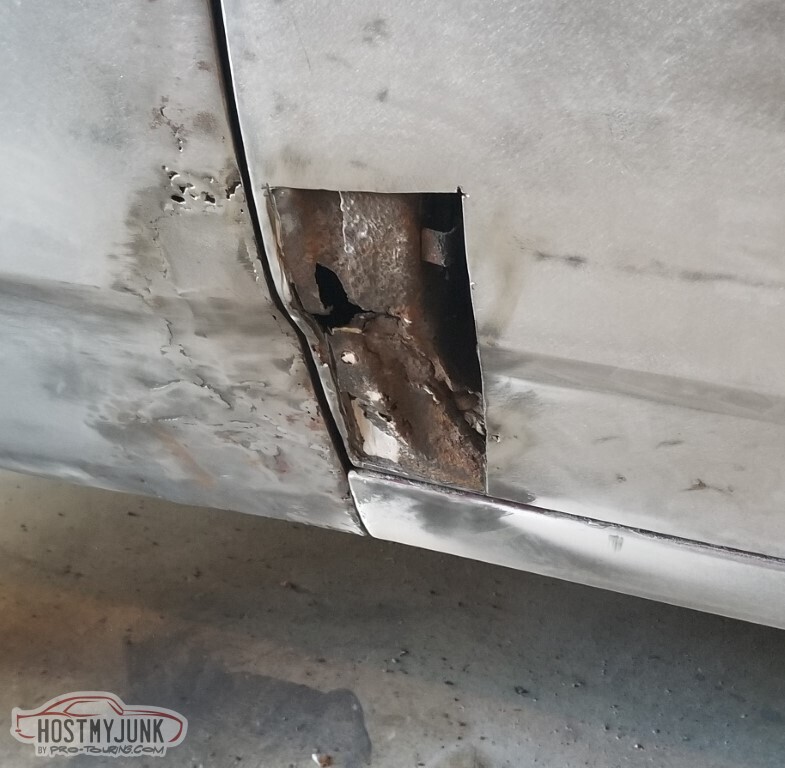
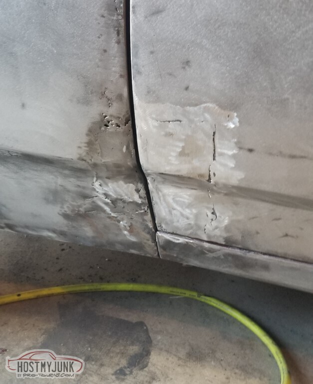
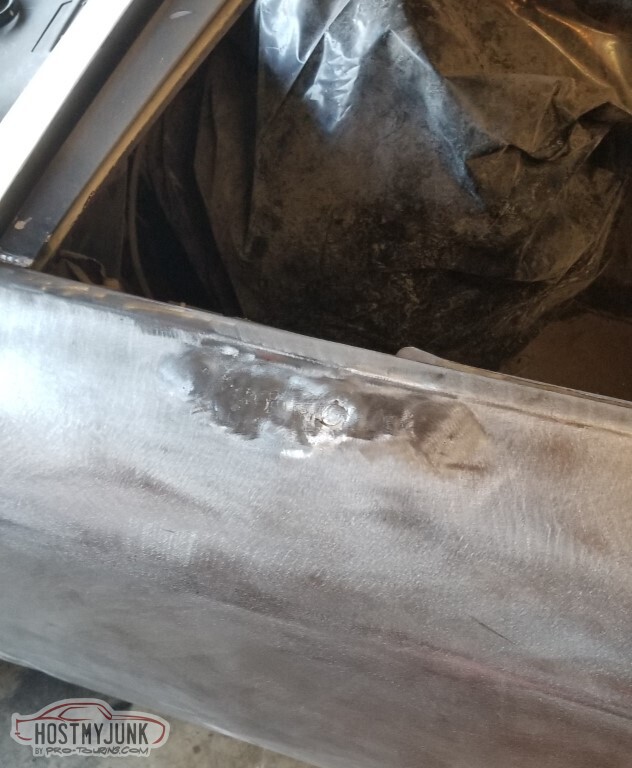
Decided to do something easier - the little rust damage on the pass side fender, and close up the trim holes.
Yes, it's true; in my absence my ability to weld didn't improve at all!
Trim holes went well enough, at least.
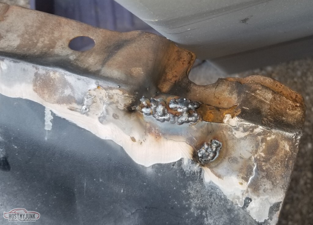
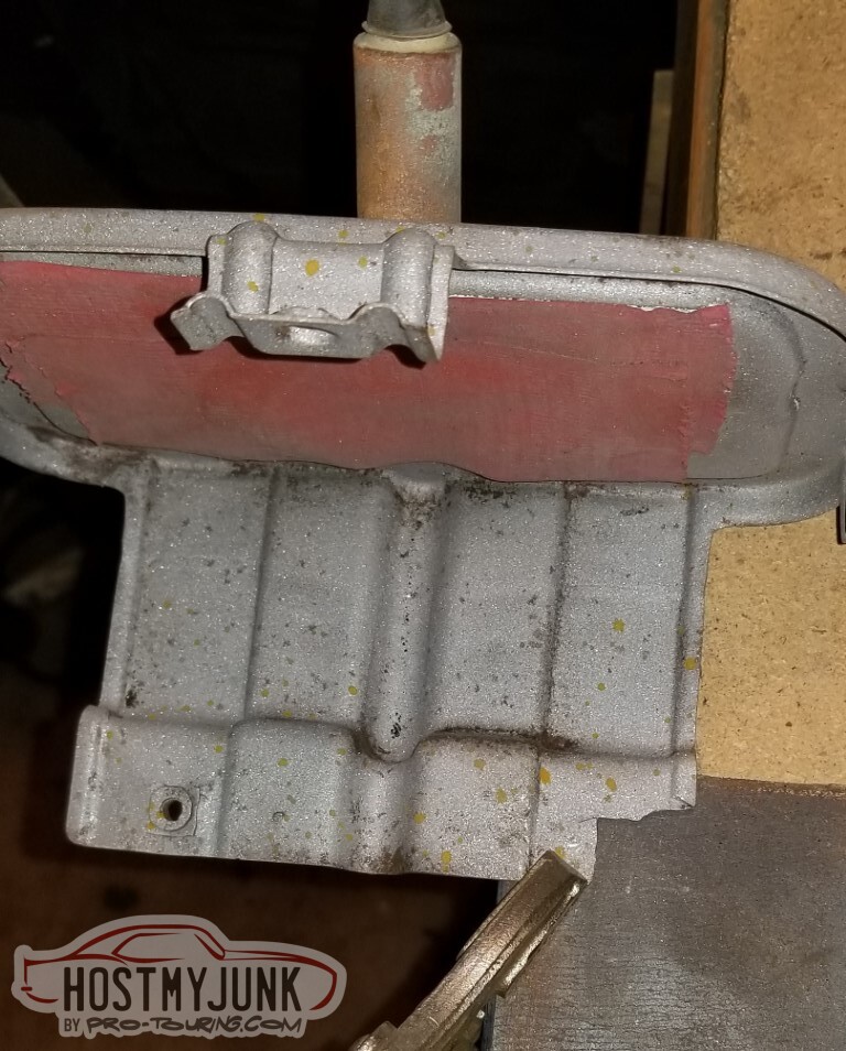
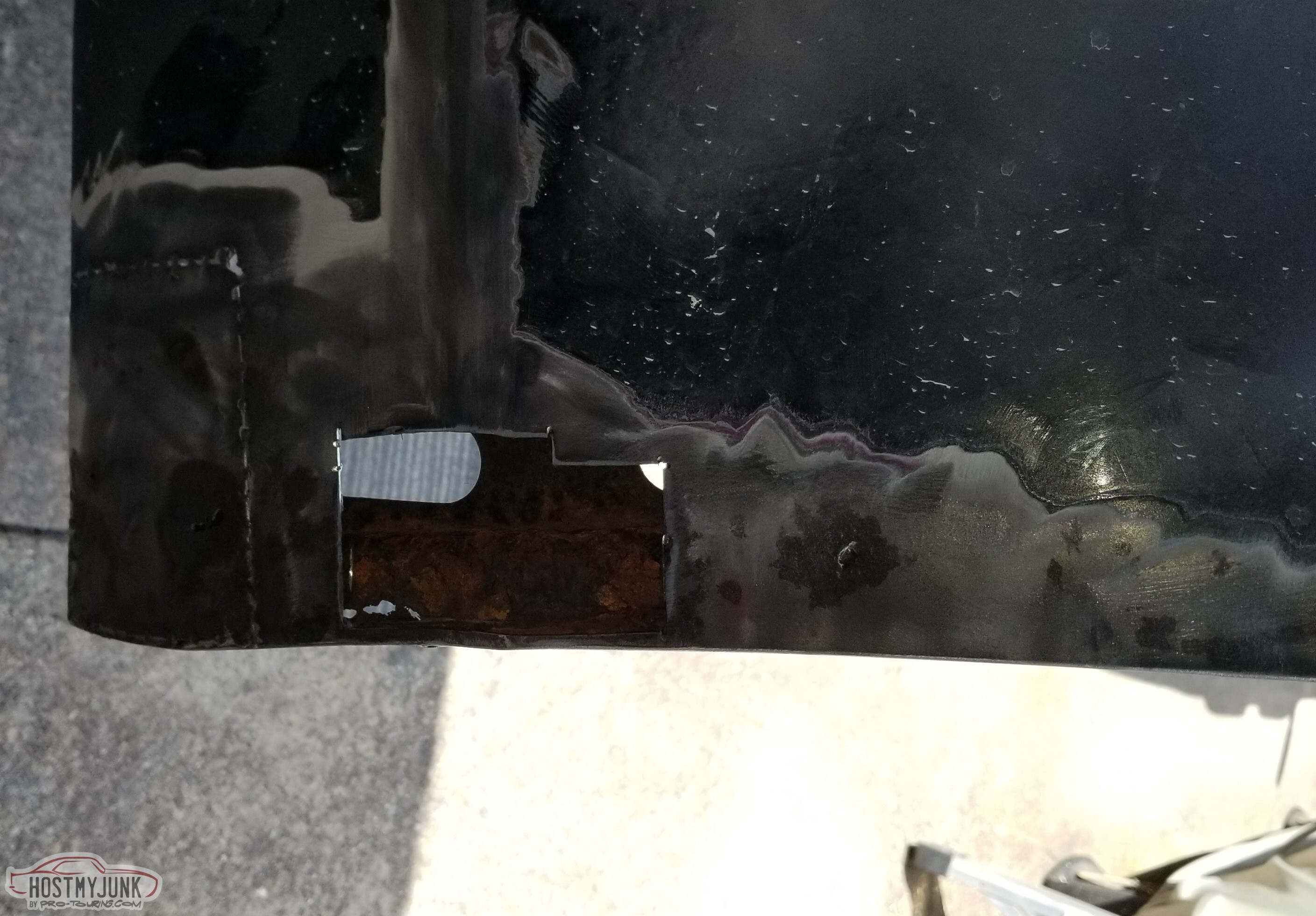
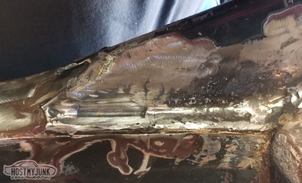
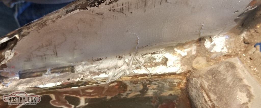
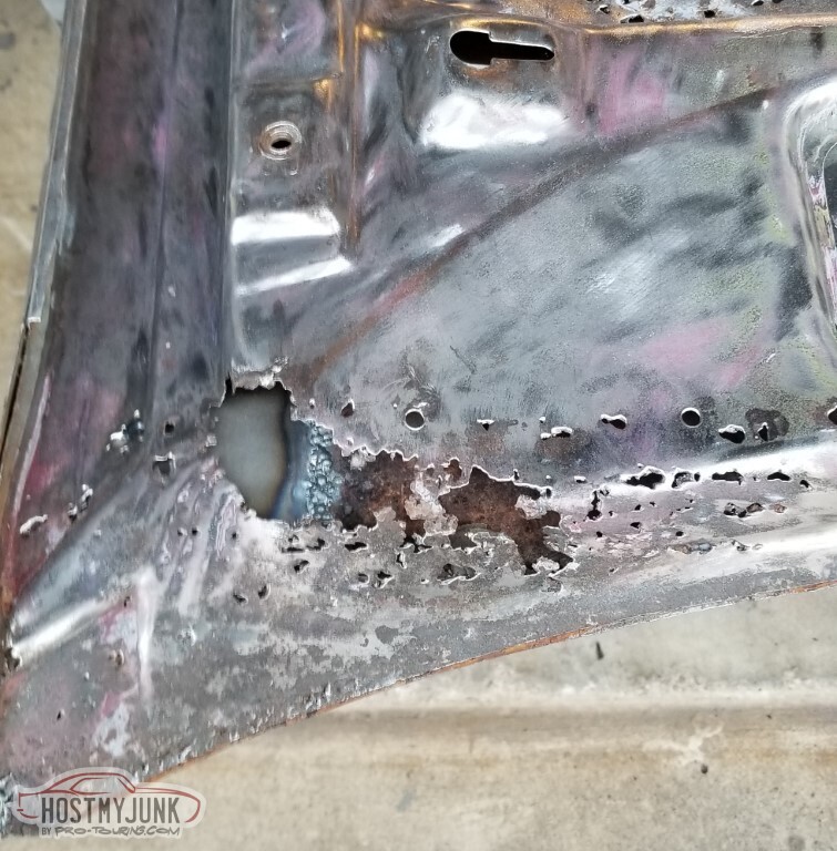
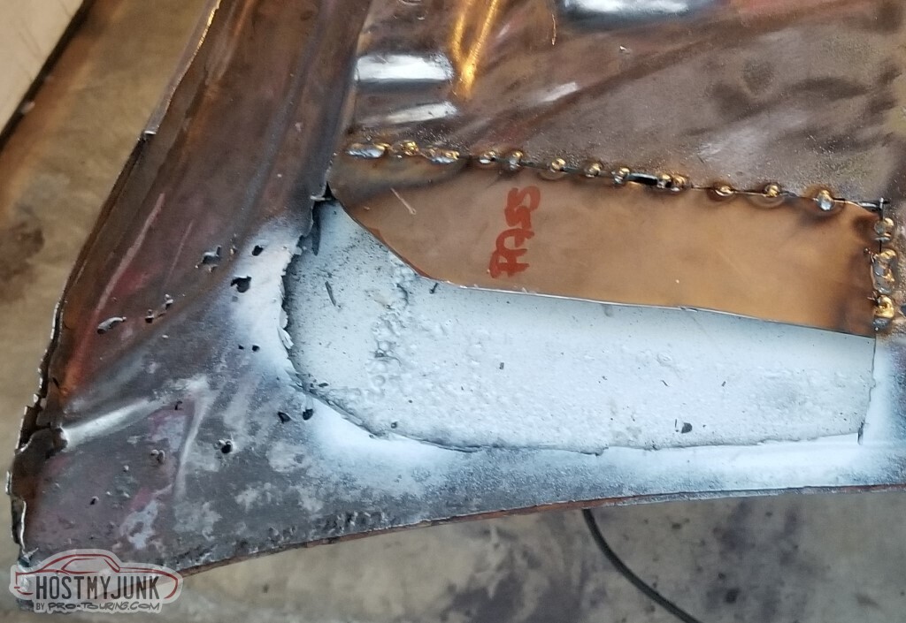
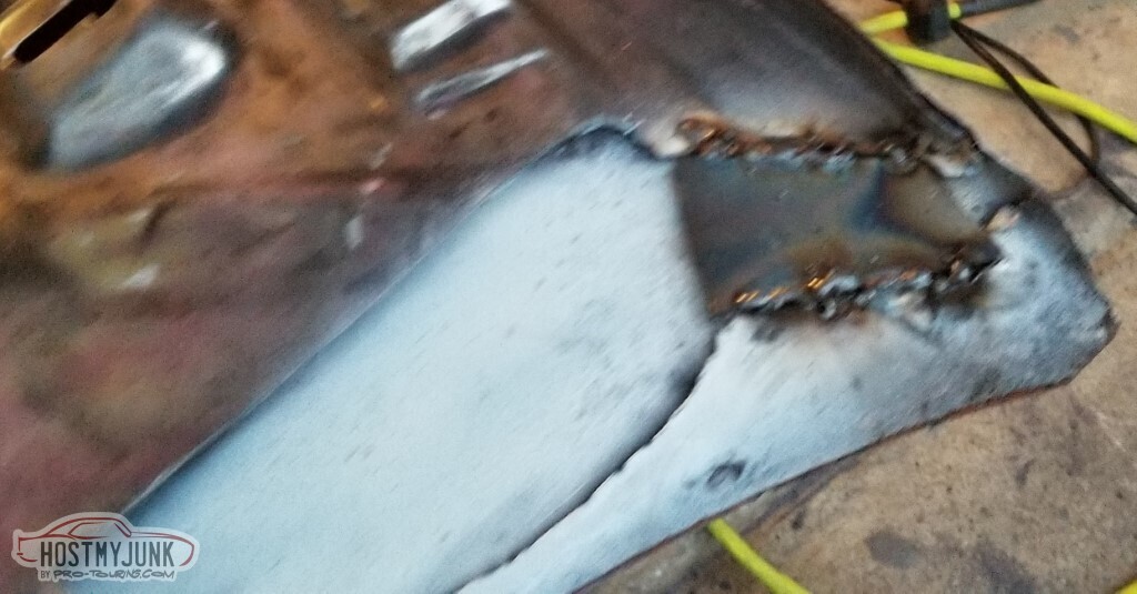
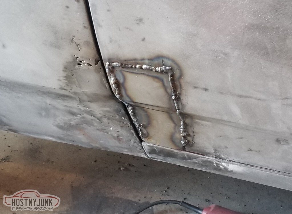
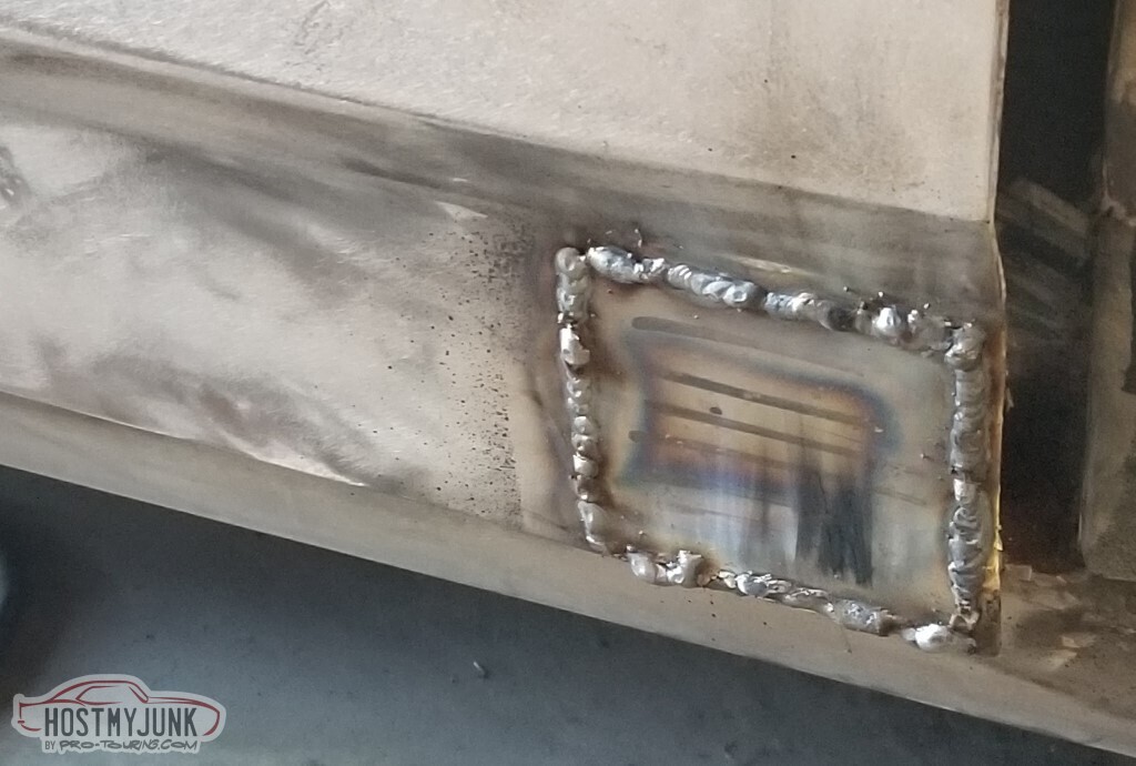
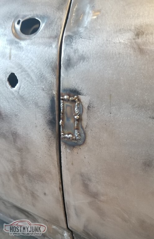
Cleaning up the back edge unearthed a rarity: a half-ass repair on this car that cannot be blamed on me!
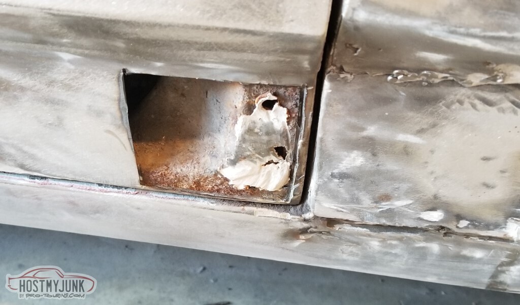
And the more I cleaned the worse it got...
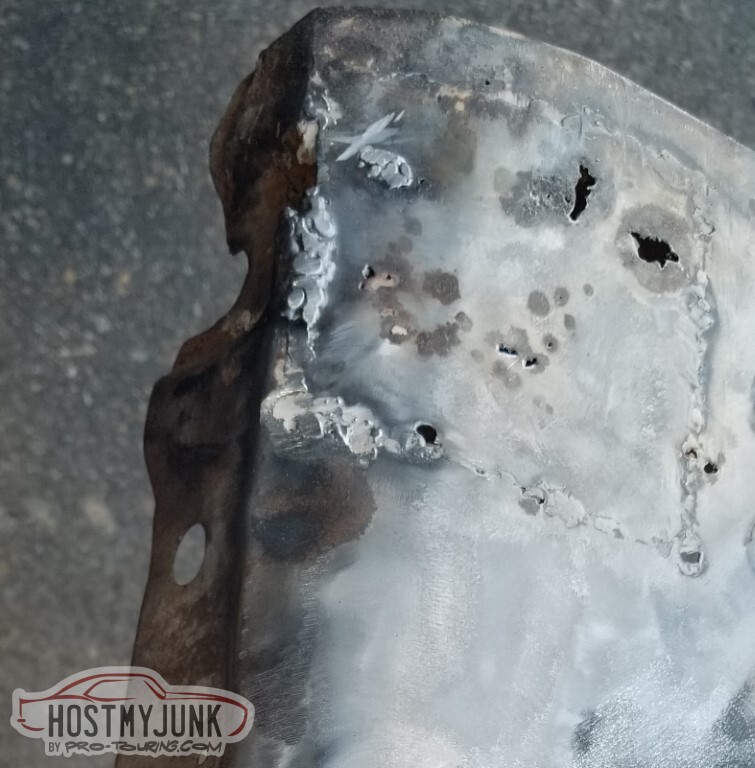
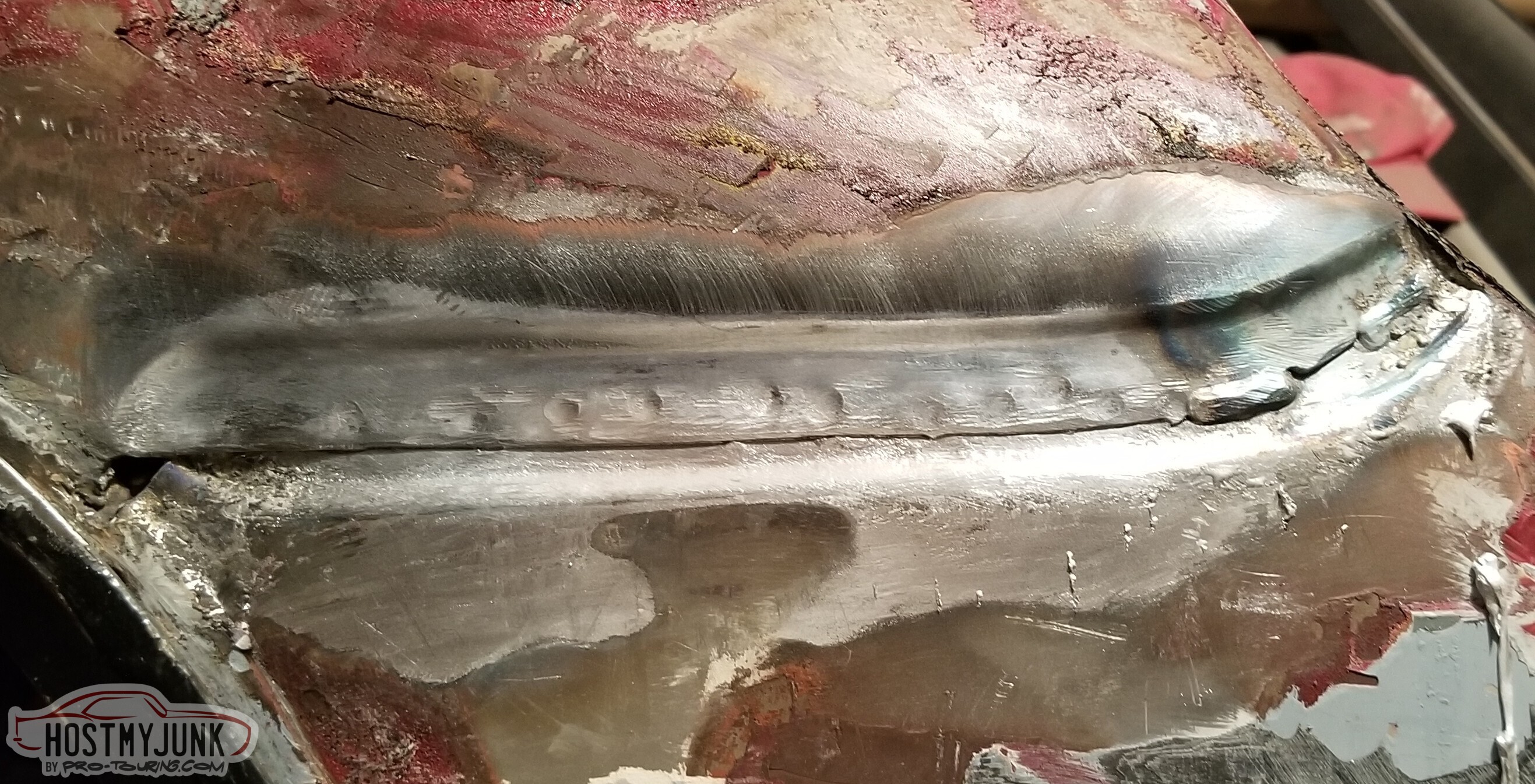
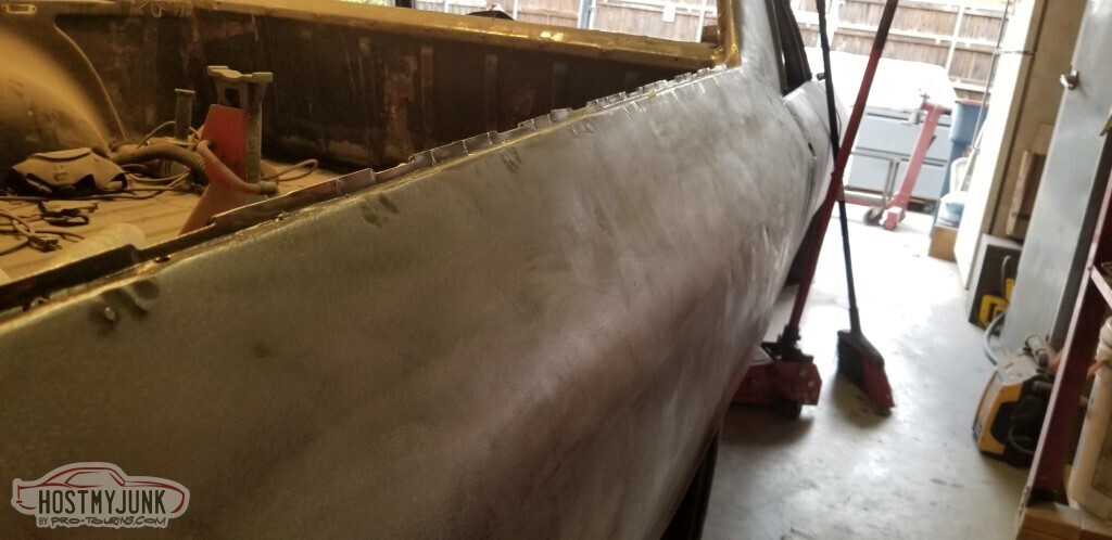
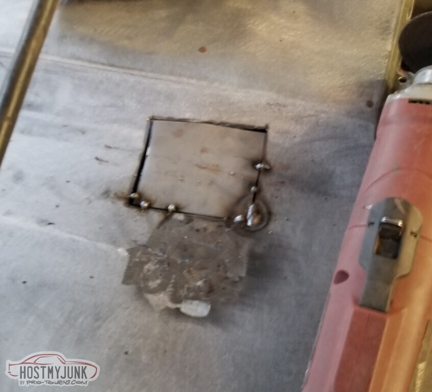
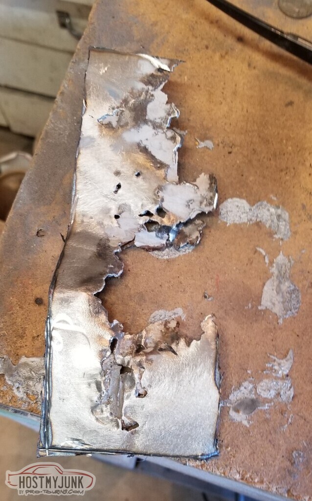
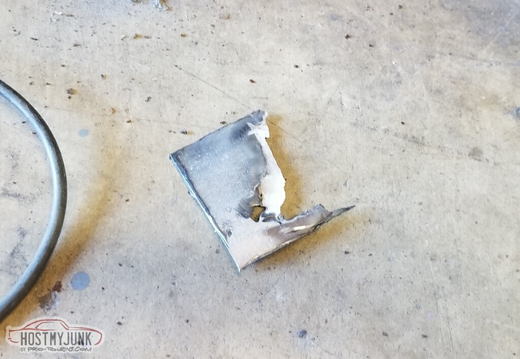
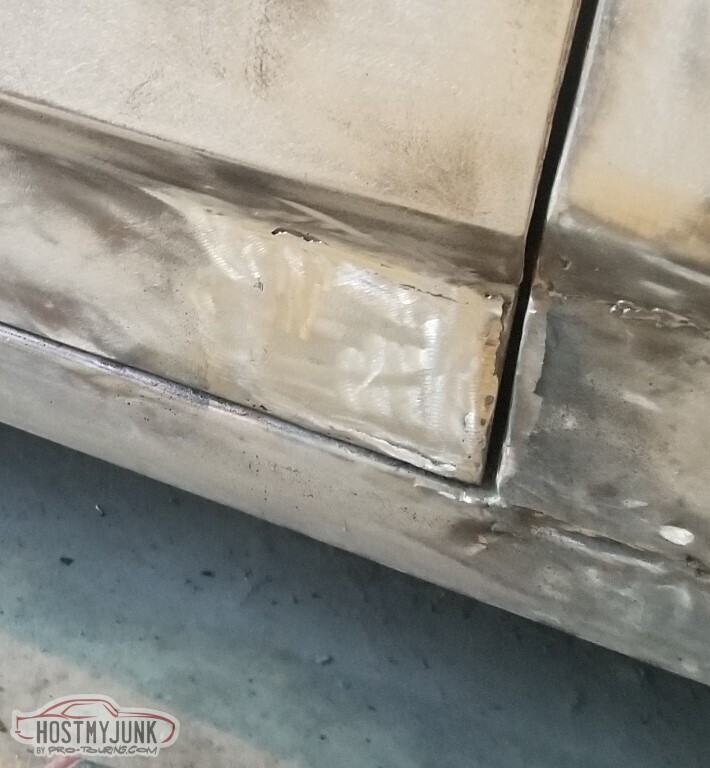
Part needed to just be cut out and replaced (okay, probably more needed that than I did)
Yep, still suck at welding. Especially in the driveway on a windy day.
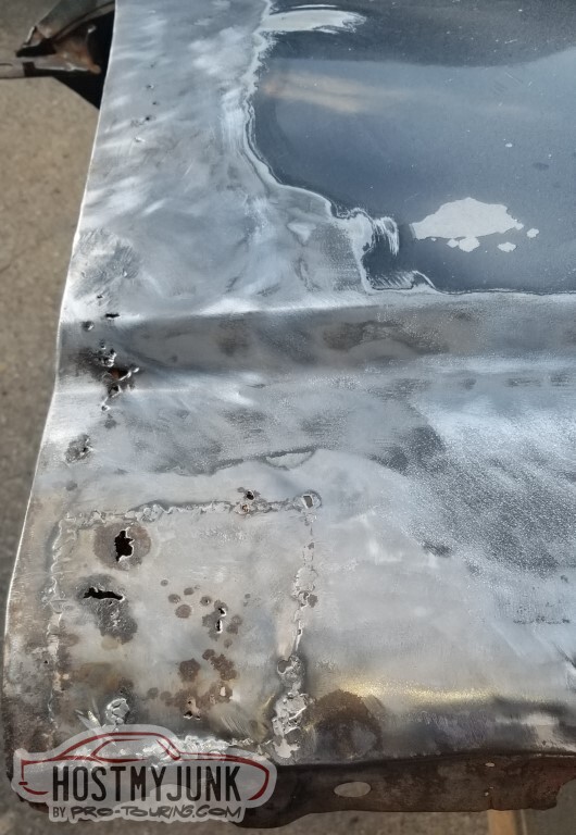
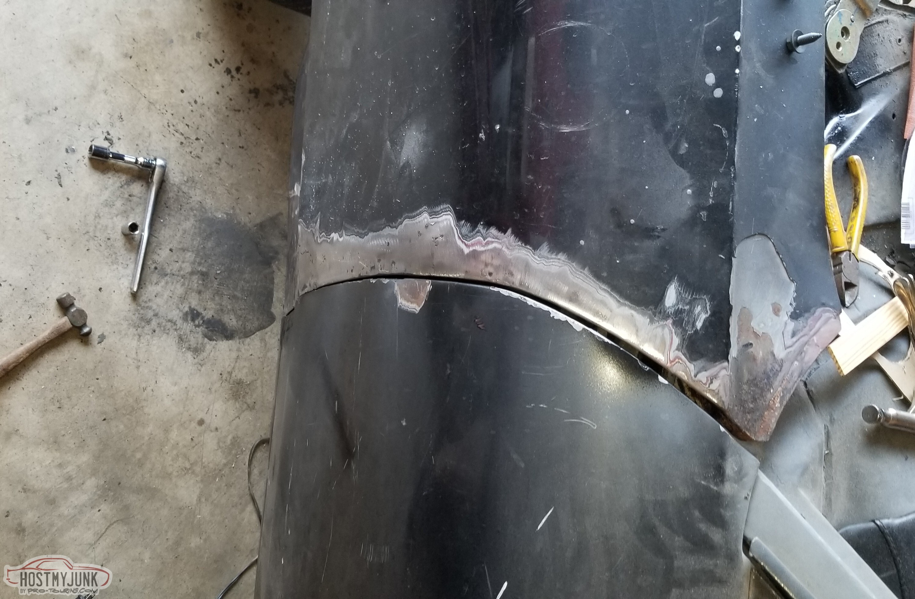
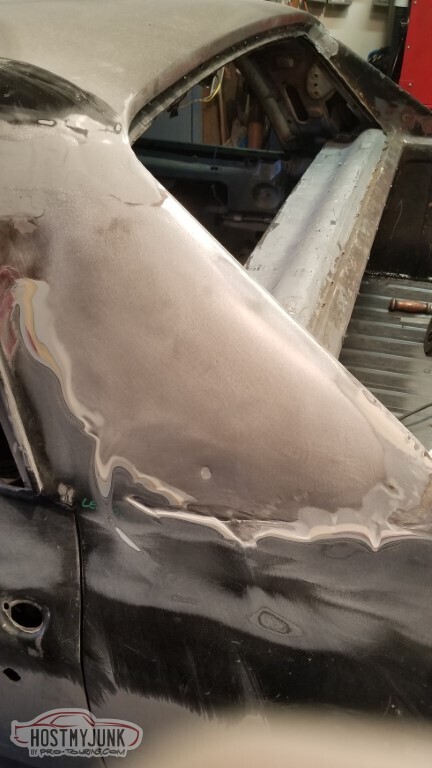
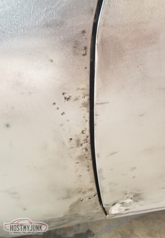
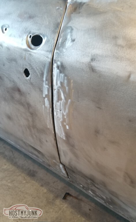
I don't know how well you'll be able to see it but there's a high spot at about dead center of this pic.
Also the bottom edge is not straight at all - did it get jacked up wrong? High-center a curb? No idea, but the other side was straight.
I am not a hammer and dolly expert but it's at least much closer now.
Still need to finish cleaning up the backside and put paint on it so I can mount this fender and call it good until I start on external bodywork.
Did some more cleanup on the husk of the old dash and started trying to figure out the mounting of the new panel. This is my view from sitting on the floor - I think the indicators will end up far too high and I won't be able to see them when I'm sitting in an actual seat, so this panel needs to be shorter. Since I wouldn't be able to do a good straight cut, I think I'm going to break out the bender and bend about half an inch to make a flange... which means I'll have to mount the bender and hopefully not screw this up when I do it.
-
05-15-2021 #85
-ɹoʇɐɹǝpoW-
- Join Date
- Jul 2002
- Location
- Mesquite, TX
- Posts
- 4,928
So, of course, once the weldery is done, need to get back to the initial plan: prime and paint the inside/where the hinge mounts. Priming is done.
Not my best work, but... it's the inside of a fender. It doesn't matter. In fact, it matters so little that I failed to take a picture once I had the paint on it.
I need two of these screws (they're for the parking lights, which are different from the Chevelle equivalent. Did not find at my local specialty hardware store. Have not investigated.
Finally got around to drilling-tapping the weld table for the bender so I could get a nice crisp edge on the dash panel.
I did not get a crisp edge.
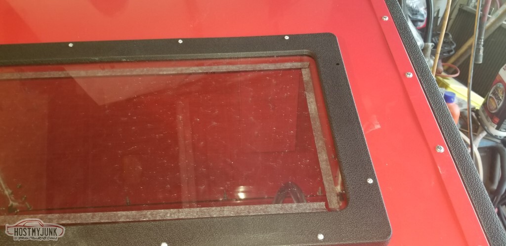
So the sandblaster is its own little story.
I like the cabinet very much, but the gun is abysmal.
I'm going to call this the "blow test": disconnect the pickup hose from the gun, and try to blow through the port into the gun. The gun that came with the cabinet flowed very little with the larger nozzle, and not at all with the smaller. Neither one worked for sandblasting.
So I went to Northern and got this gun. It worked pretty well, but the aluminum nozzles are absolutely a consumable - I wore out both of them from this kit!
Instead of rushing back up to Northern to get new nozzles, I tried the smaller gun from the old cabinet I threw away... and it worked better than any of the others.
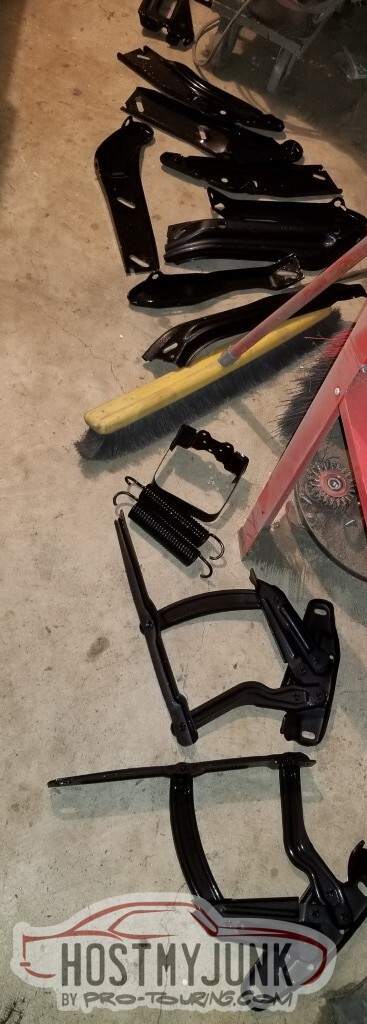
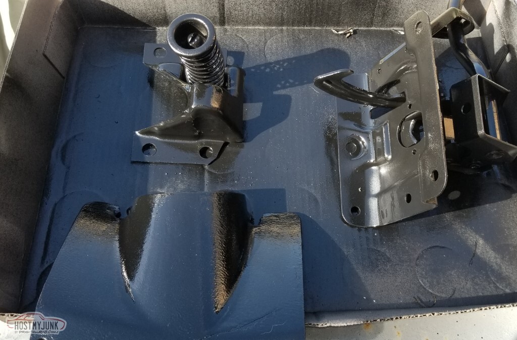
I made a pile of blasted parts. I really only *needed* the hinges and springs (and I suppose the washer bottle bracket) but as long as I'm at it....
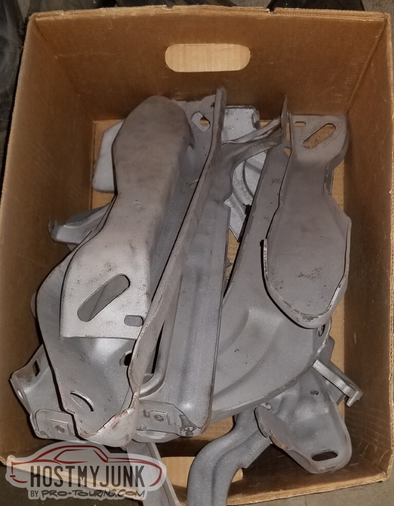
...and primed, because that's the next step, and it was warm enough to do so.
While waiting on the primer to dry, spent more time on the harness - need to extend the harness to the ECU by about three feet to mount up by the battery. It's very slow.
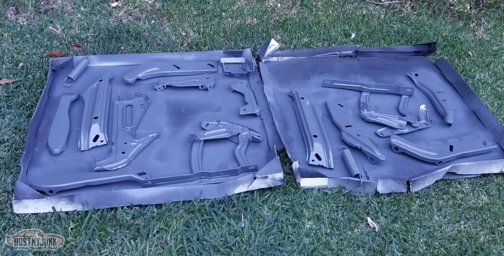
Warm enough to put paint on these parts. They came out really nice. I need to wrap the bumper brackets up in newspaper and put them in a box to protect them, since I won't need them for a while.
and then, of course, the pass fender fell over and got a nice dent. Don't know if that's really visible here or not.
Suppose next up is more extending-of-wiring, the driver's fender, and the dash. Need it to be warm enough to shoot primer and paint on the fender though so maybe I should hurry there.
-
05-15-2021 #86
-ɹoʇɐɹǝpoW-
- Join Date
- Jul 2002
- Location
- Mesquite, TX
- Posts
- 4,928
Yeah... the goal here was not to spend weeks doing this. That goal was not met.
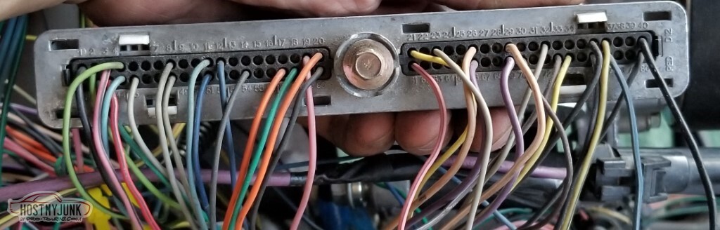
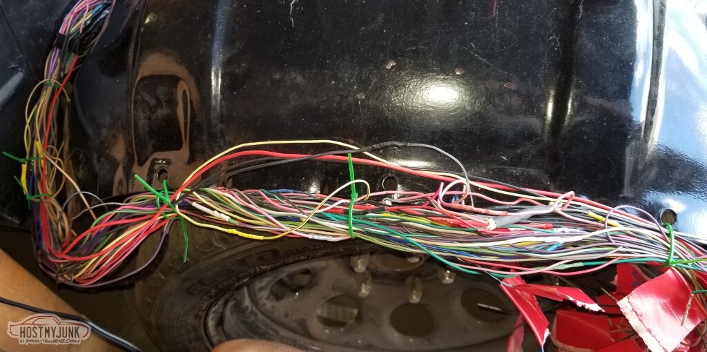
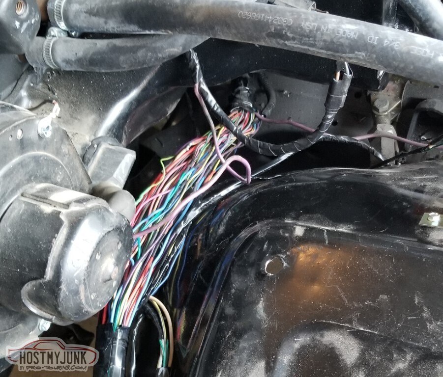
I ended up removing every pin from the connectors and marking them (R46 for Red 46, etc.), shown here in progress.
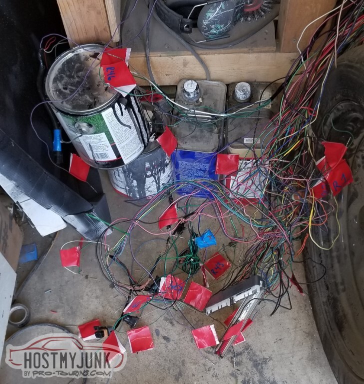
The plan was to separate the red and the blue connector wires. Made a little tougher since some wires essentially connect the two.
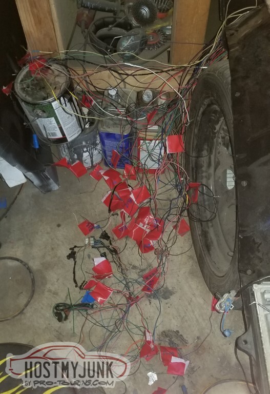
Bundled.
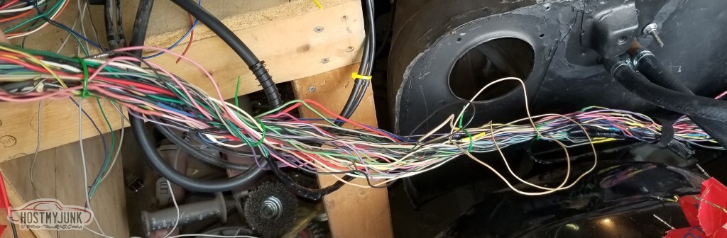
Also needed to extend the coil/injector wires.
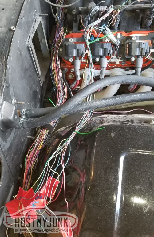
For validation - run along the outer edge of the inner fender
More lengthening and bundling.
Put it all back together after lengthening everything and it was still a horrible rats nest.
Back apart. Problem - in part - was because I just plugged all the red pins in and they ended up routed around each other, and same for the blue.
New plan: Plug in red 1-10, 41-50, 11-20, 51-60, etc. Wrap the quadrants separately. It's still a rat's nest but not nearly as bad.
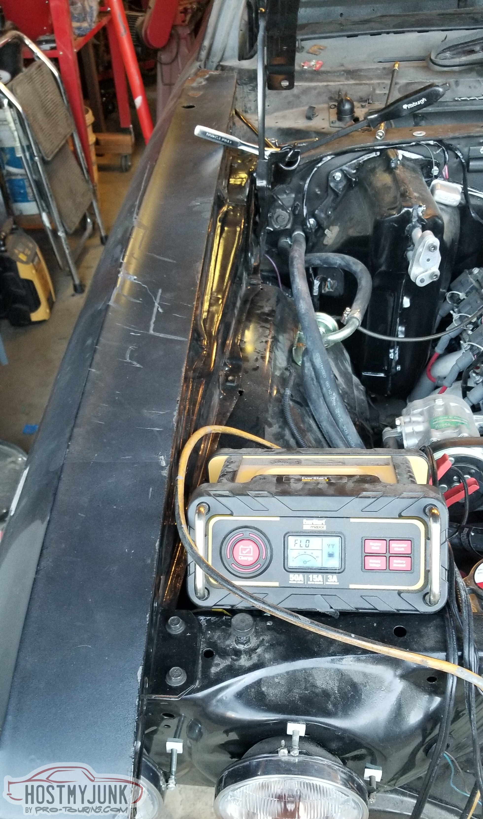
Plug everything in, try to start the car: dead battery. Tries to spin the starter, no luck.
Bought a replacement battery charger.
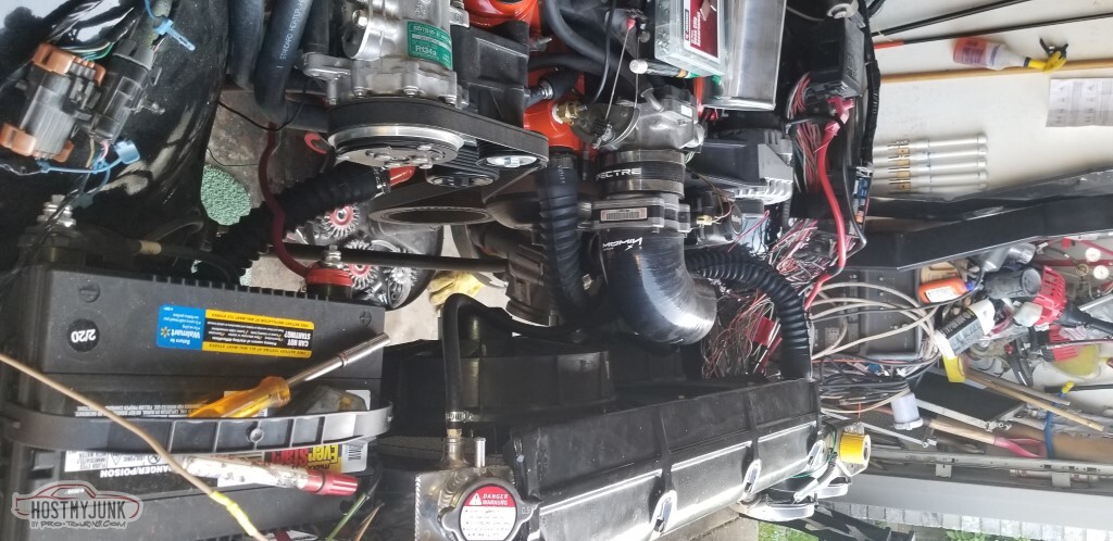
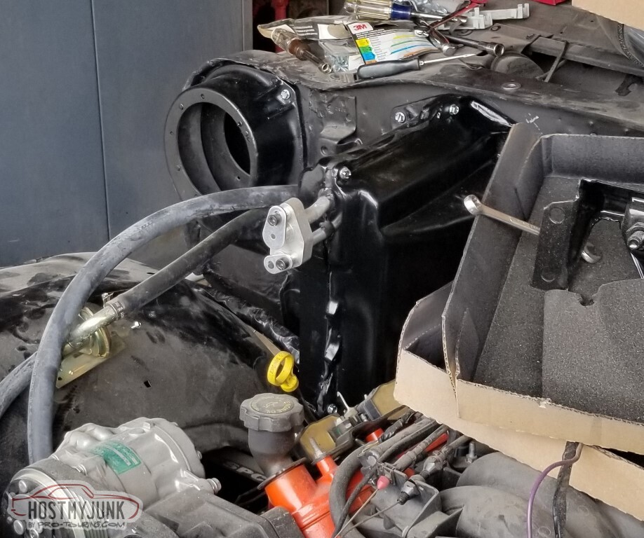
Moving on to the next task: the AC box. I don't know what I'm trying to validate here beyond that it clears the engine, which I already knew.
<tr><td>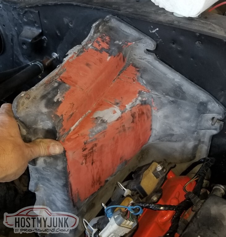
Started wrapping the wires as the battery charged.
After a couple of days (trickle charge), the engine spun over, would start and then die pretty much immediately.
Did I miss a pin? There's no codes reported (beyond "MIL indicator not found", which I knew). The sensors all seem to be working per EFILive.
Maybe the battery still needs more charge.
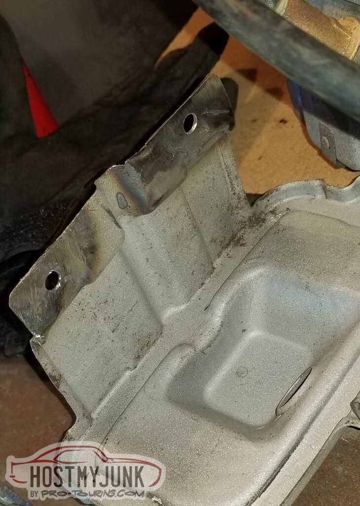
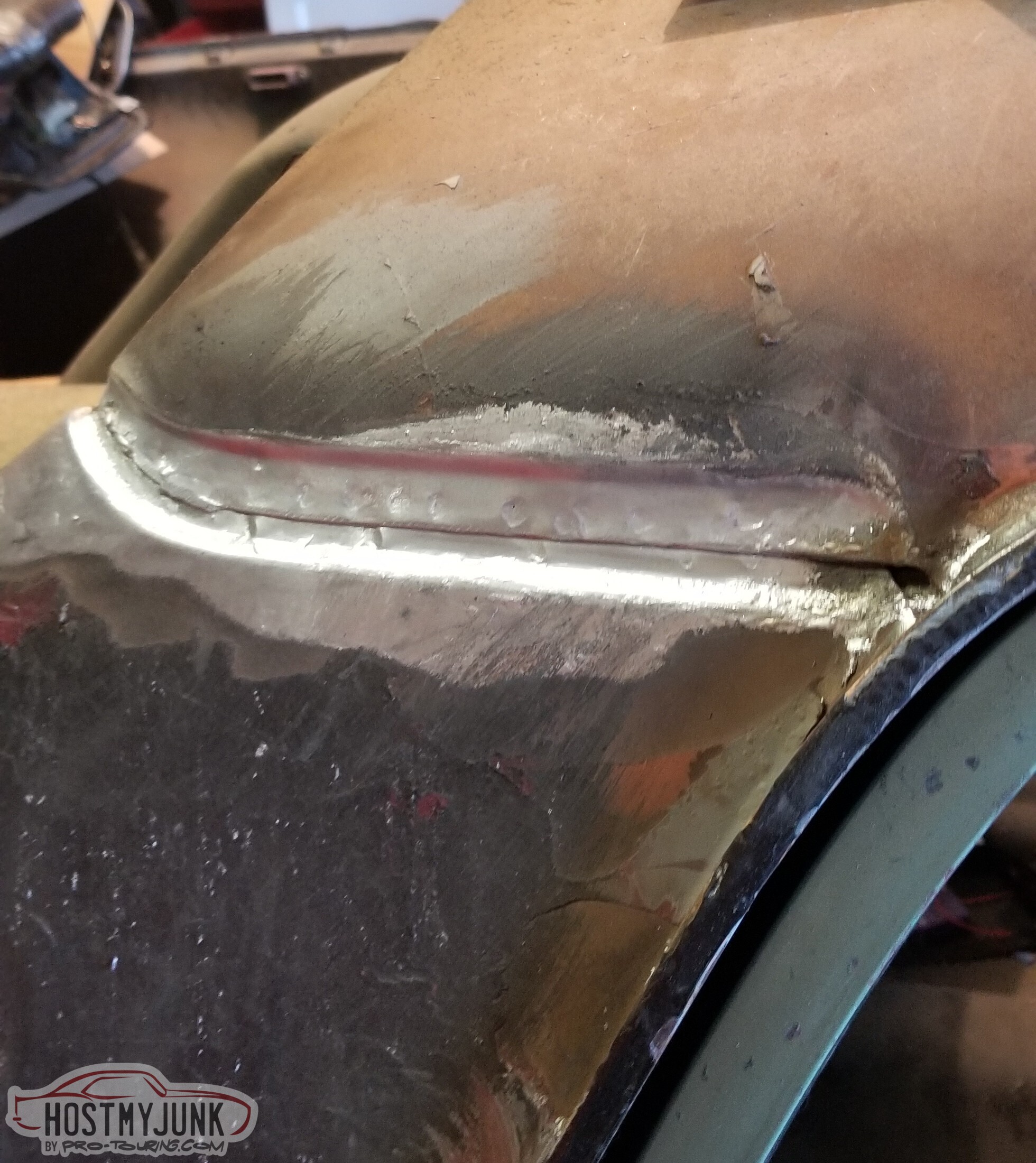
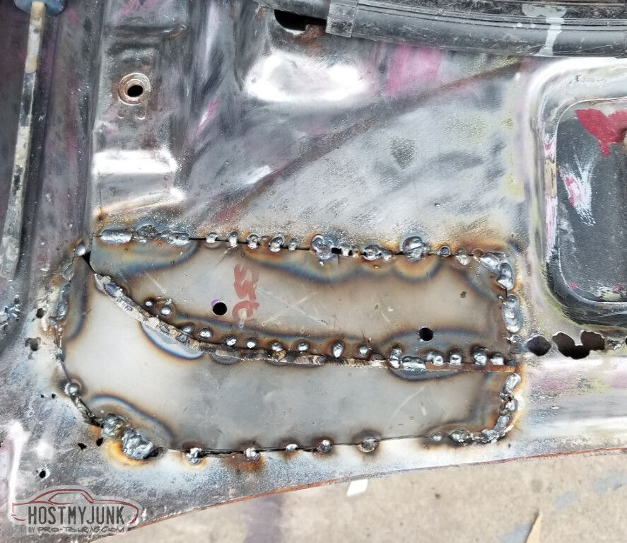
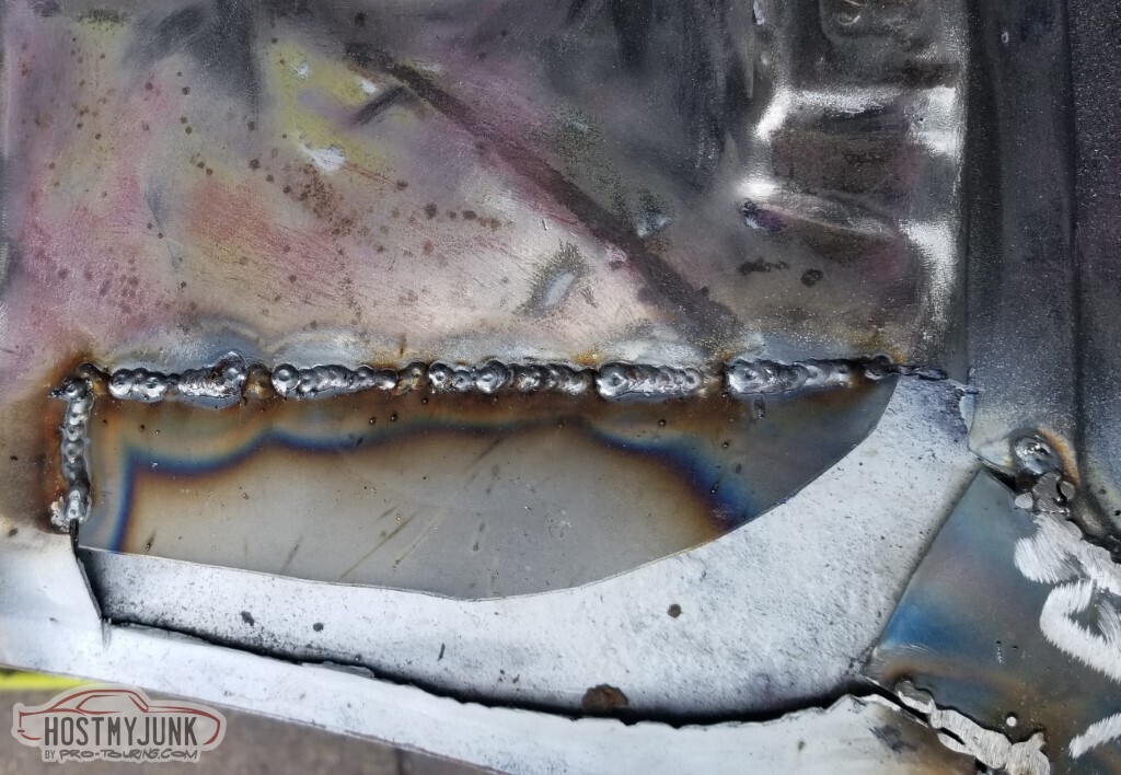
Move on to the next task: the damaged parking light mounts. This is the better of the two.
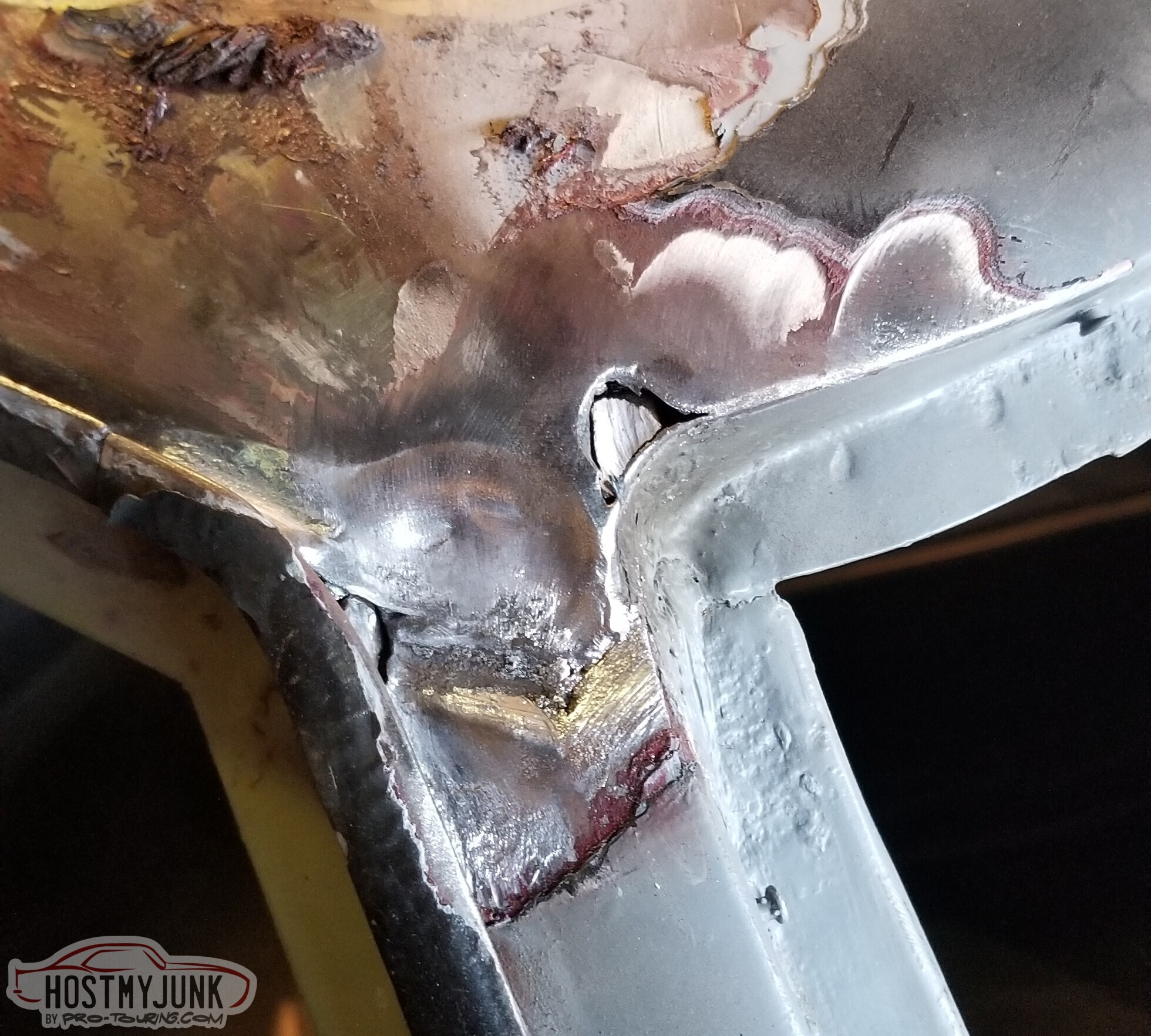
And this is the worse.
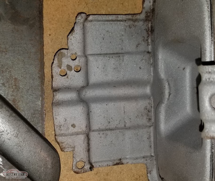
Reconstructed the missing corner. Still need to weld on a #8 nut to finish this out, then re-sandblast and paint.
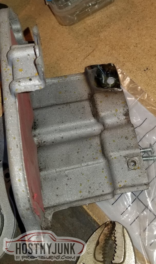
Same on the worse one - filled the holes, reconstructed, new mounts. Need to weld on the nuts, resandblast, and paint here too. Also may need to replace the bulb socket.
One of these housings has a broken bolt in one of the lens mounts; still need to handle that too.
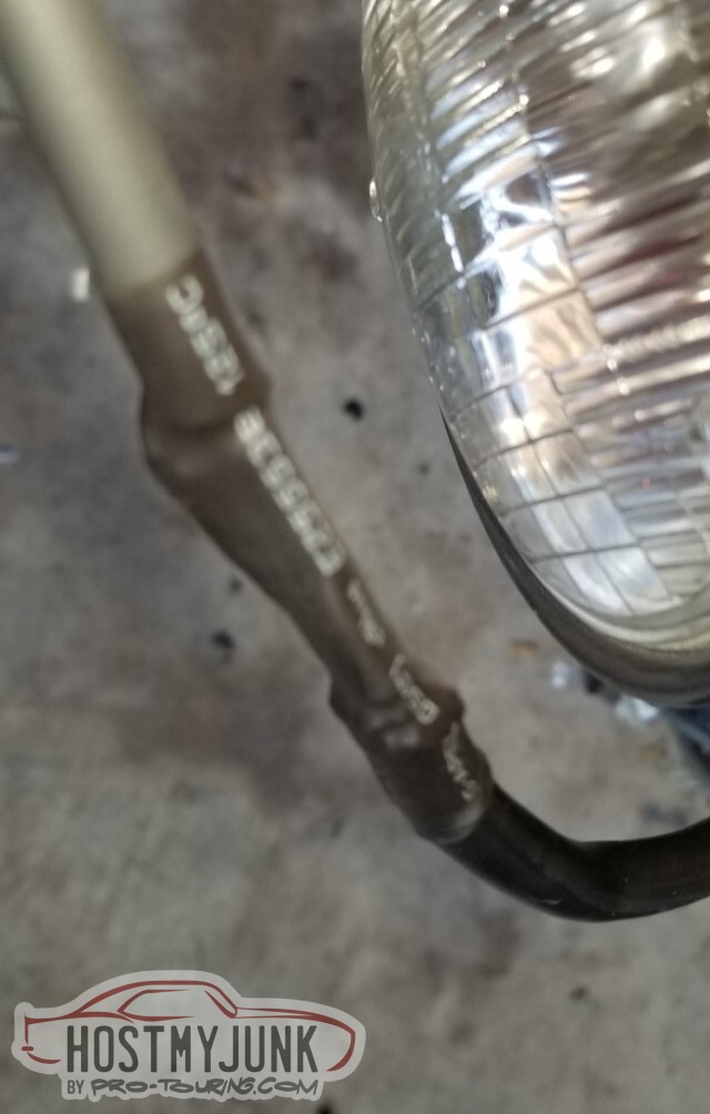
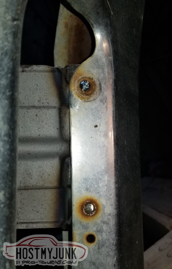
I am not quite sure how this has occurred, but the epoxy primer and implement enamel have flaked off here at the headlamp adjustor. The adjustor is also trying to pull through.
There is a difference between the "headlamp adjusting nuts" (skinny) and "license plate nuts" (thick). Replaced the skinny with the thick.
Apparently I have a leak at the oil pressure gauge. Tightened.
Minor concern that the PCV hose has a crimp. Maybe it's too long, or too short, or maybe it doesn't matter.
After going through all sorts of possible causes (VATS? Low voltage?) the answer became clear. If only I'd looked at this gauge (that's still in a box on the cowl); it was correct.
Added fuel and the car started right up. No new codes so I guess I hooked everything up correctly.
Paint for the AC box. Guess next up is to mount the box and the ECU so I can put the fender on.
-
05-15-2021 #87
-ɹoʇɐɹǝpoW-
- Join Date
- Jul 2002
- Location
- Mesquite, TX
- Posts
- 4,928
The mount for the ECU is "done".
I think it needs another bracket to connect the top of the mount to the core support though.
pictured with the computer attached and hooked up.
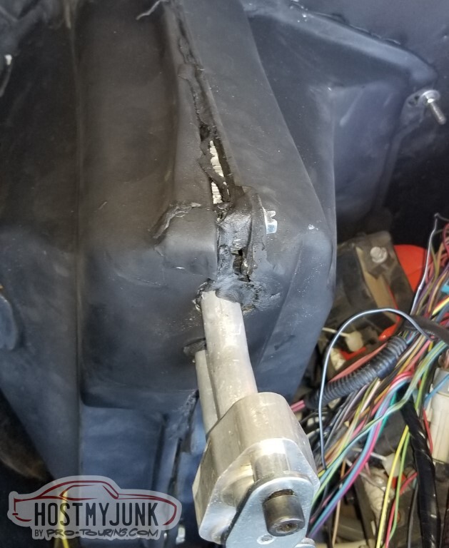
Tried again with the AC box. It split at the front mount again. Apparently "flat" is not sufficient for the back, it needs to be a little concave to force the front together.
Corrected the brackets for the parking lights. Oddly enough, the spacing on the screw-holes differs between the sides.
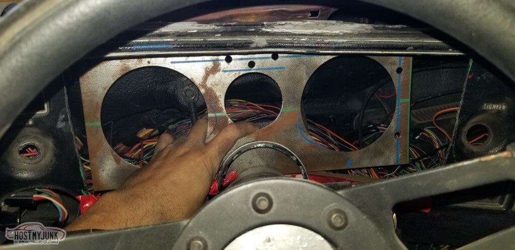
Used duct tape and cardboard to figure out just where the dash needed to be to clear the column brackets, etc. Here is the first time the gauges have been "installed" in the car.
I made the upper panel out of 22ga steel that was sitting around. Got it to line up well, but that metal is so thin!
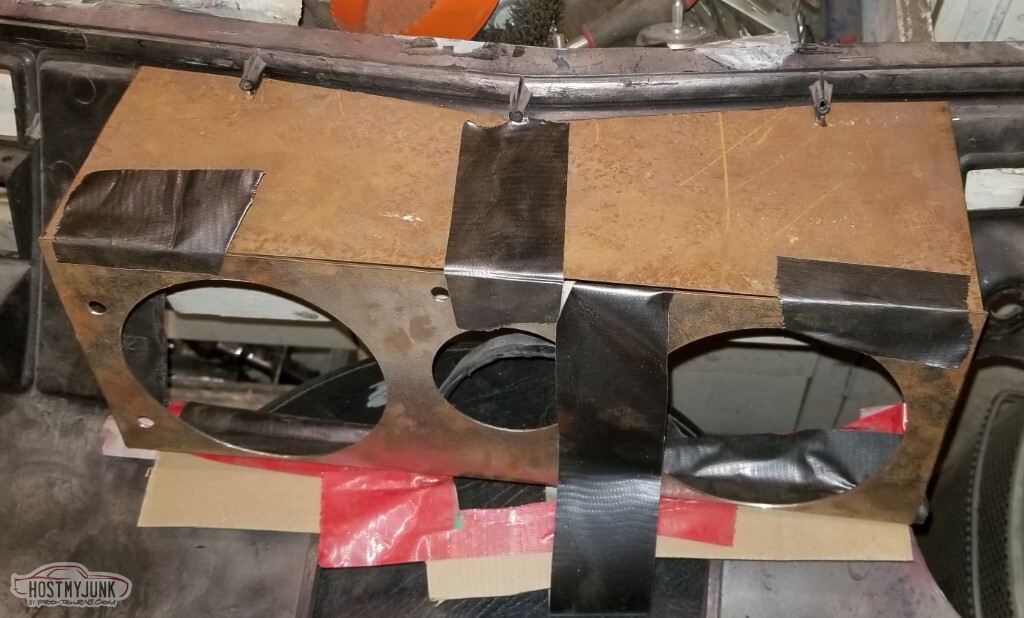
Picked up some 16ga instead. This is proper. Used the thin panel as a template.
Then added the mounts to the upper panel.
Test-fit again, with the upper panel in place and duct-taped to the face, on the bottom I added 3/4" more metal to push it back a little.
Zip ties to hold the dash carrier in place, whee!
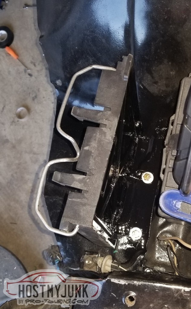
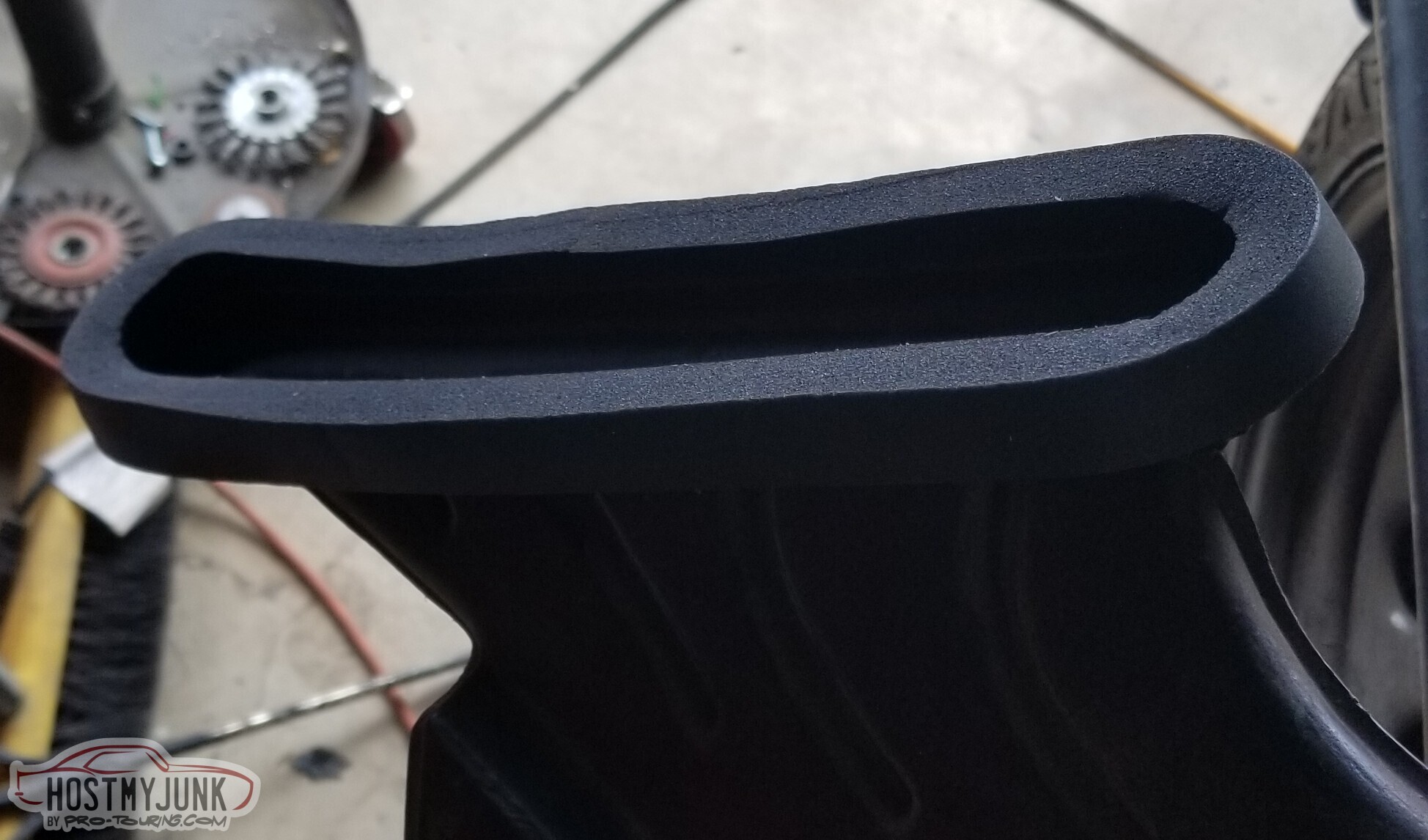
In the initial test-fit of the AC box with the bundled wires, it became clear that I am not going to be able to run the wires between the inner fender and the bottom of the AC box - there just isn't room. So - let's make a channel for them.
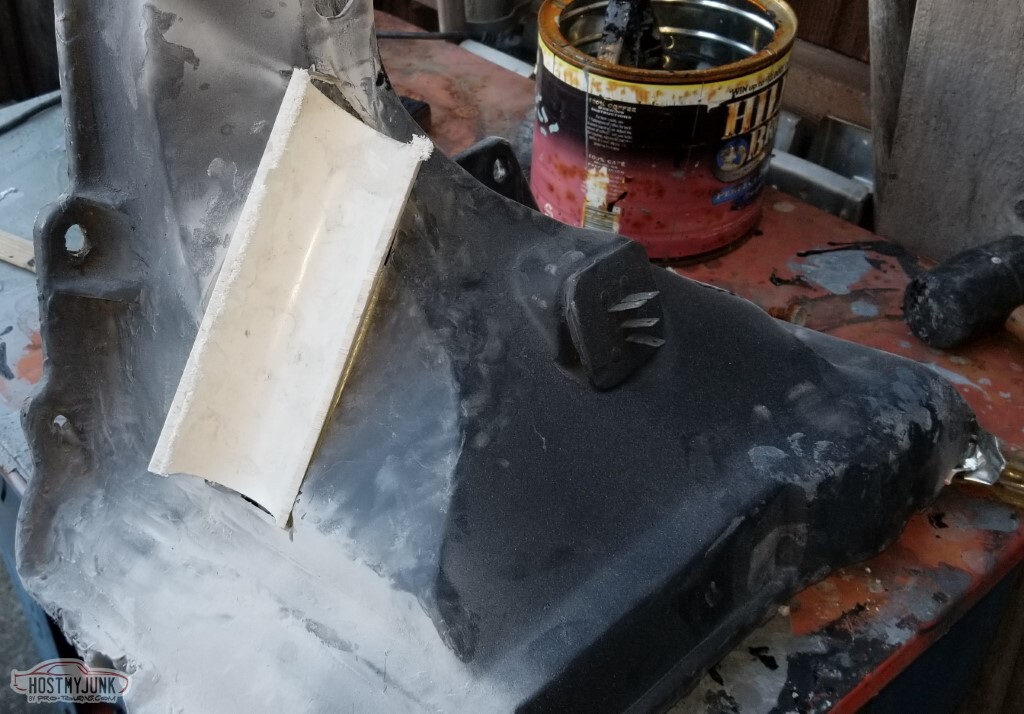
It looks roughly like this. It still needs work.
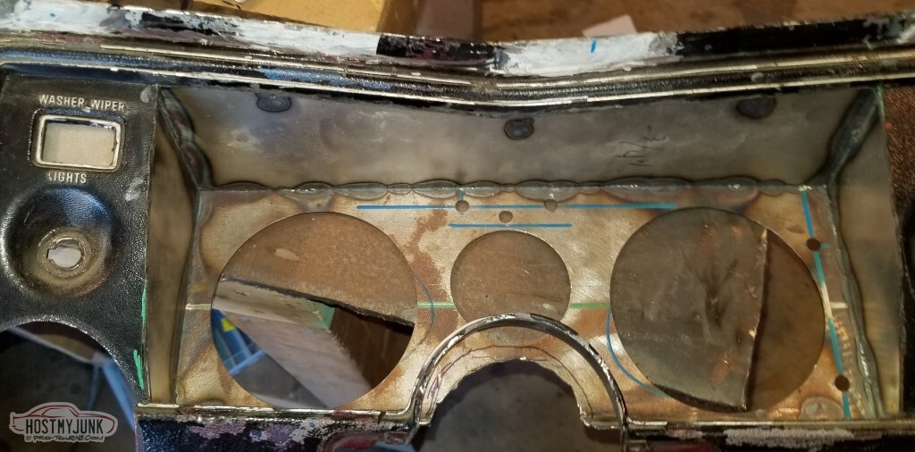
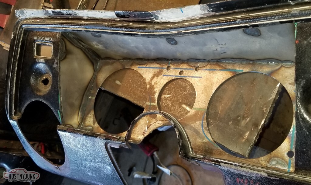
The dash panel is coming together here. You can see the side panels, the lower edge, the lower mounts, and the close-out for the wiper switch there on the left. Everything is welded, and I didn't completely screw it up!
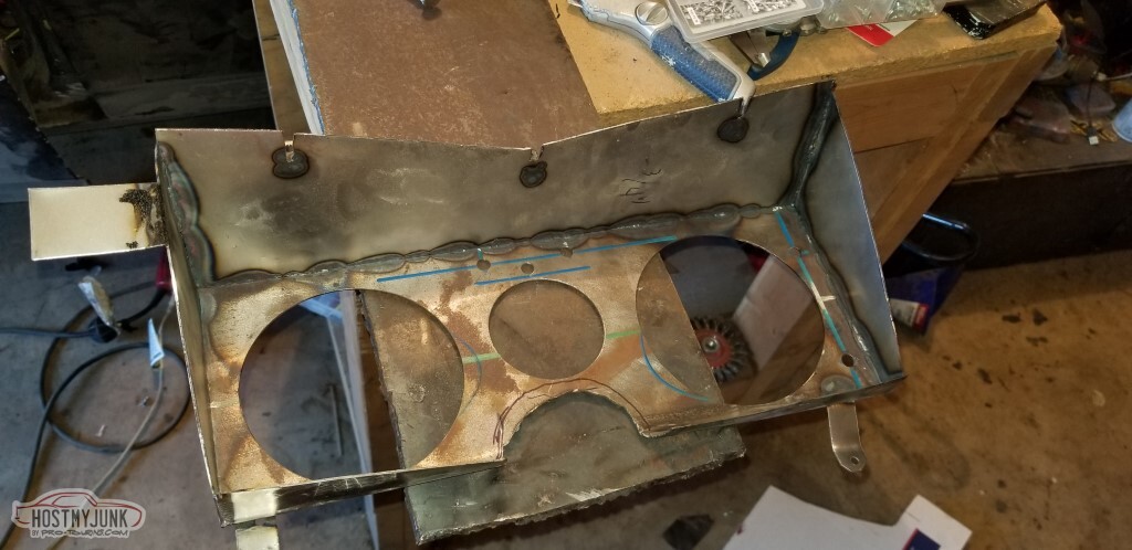
I think it looks great, except where the beaver chewed out the column notch.
And of course my carrier has seen better days. It's only 50 years old, I don't know why the plastic has damage to it.
Used some exhaust tubing for the column surround.
Welded in.
Next step is to sandblast the whole thing, prime, and paint... but it's been in the 40s and 50s for highs, not quite warm enough for things to cure.
The plastic dash carrier needs some attention with some JBWeld to try and correct some of the damage. You can maybe see the initial repairs to the upper edge in the earlier pictures.
The wrapped wire bundle passes through the channel. I want to bore out the PVC that I fiberglassed in there - it doesn't need to be as thick as it is and I'd like more clearance.
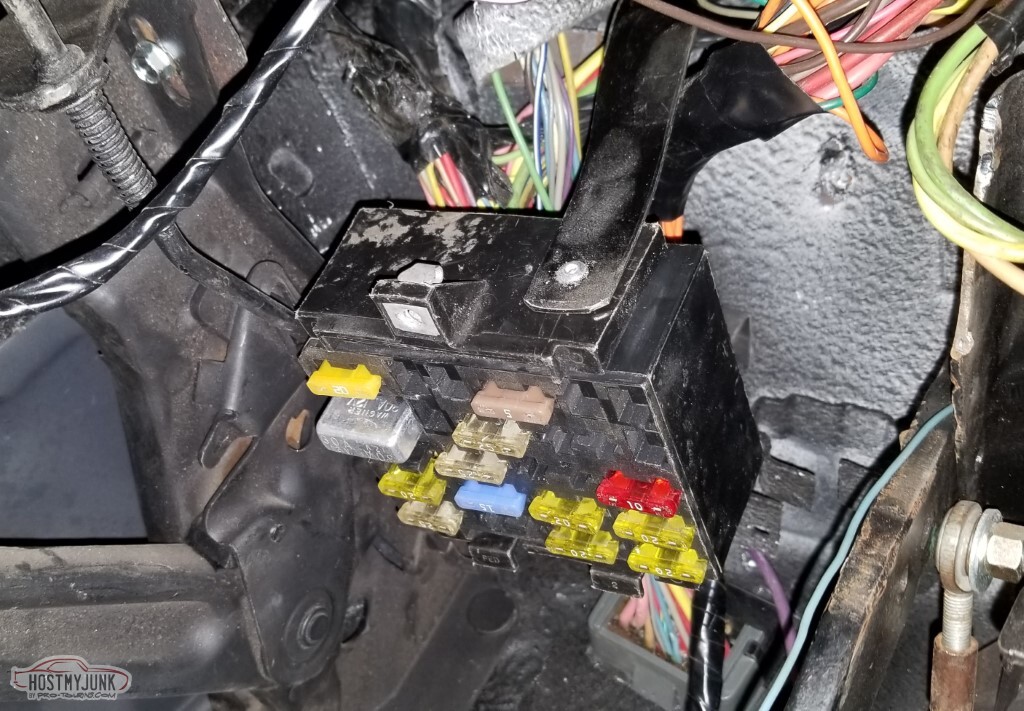
Hard to tell what's going on here, but the interior fuse panel is mounted up under the dash (one less thing dangling near the pedals!)
The mount for the Clutch Anticipate switch is next up. This is ~10ga steel for the bracket - should hold up well enough.
And it gets welded in.
So does an equivalent bracket for the two brake switches. Yes, I still haven't learned to weld.
I need to figure out how much clutch pedal travel I'm supposed to have/how much I need so I can mount the clutch stop and the clutch safety switch.
-
05-15-2021 #88
-ɹoʇɐɹǝpoW-
- Join Date
- Jul 2002
- Location
- Mesquite, TX
- Posts
- 4,928
2021-05-15 edit: This ends the archived posts; additions will be slower.
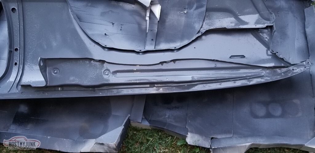
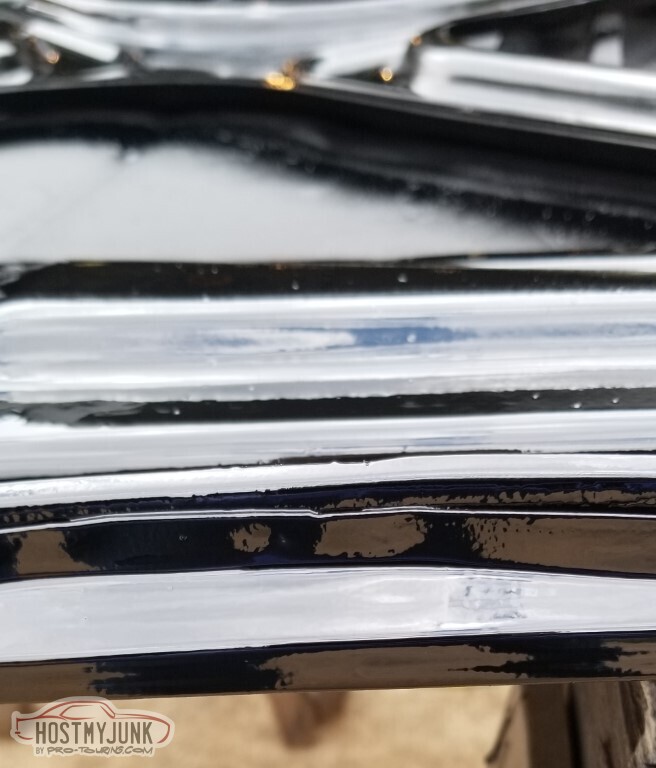
The most high-tech of paintbooths:
A full coat on the dash carrier too:
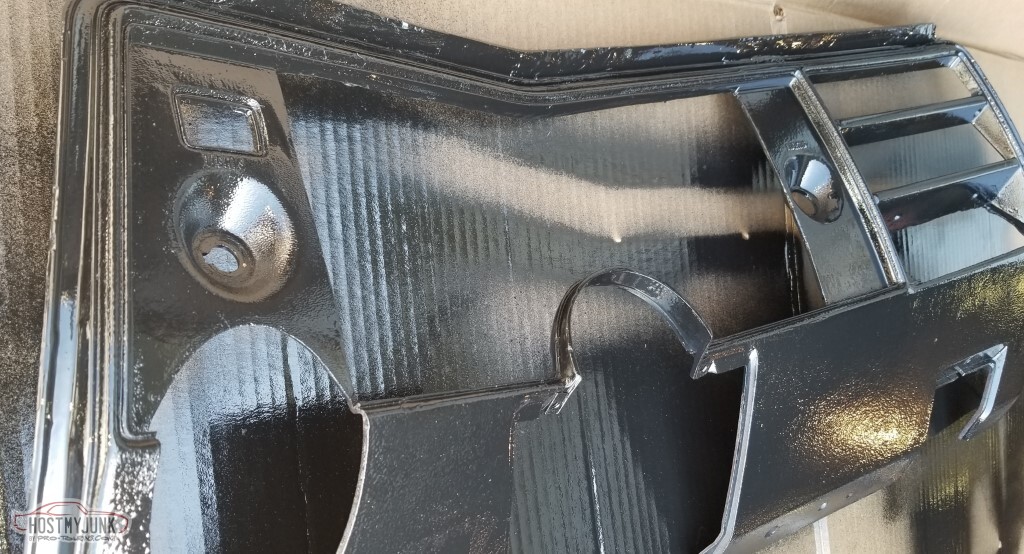
Various trim as well:
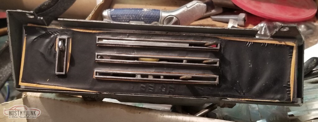
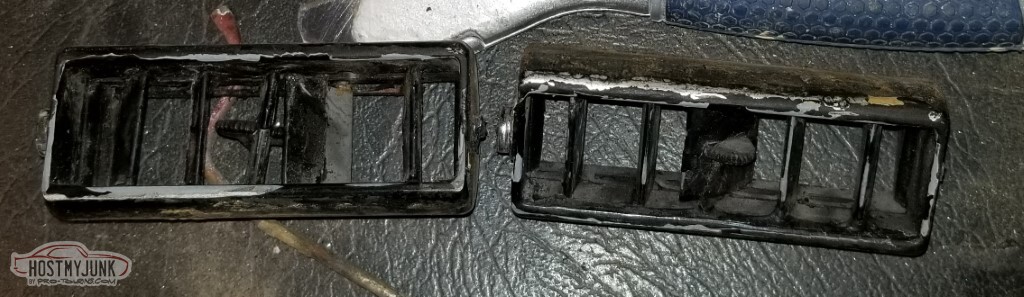
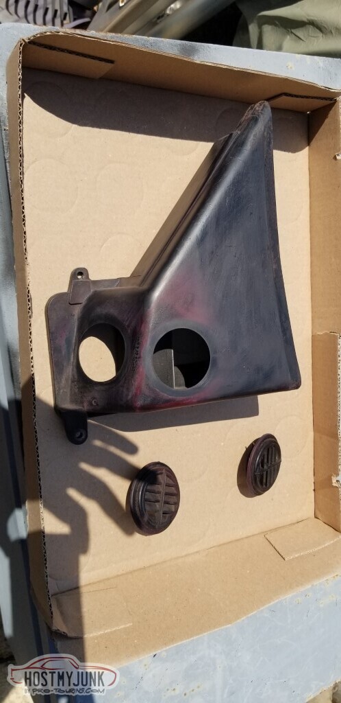
I need to clean up the center dash vent - it's *rough*. By "rough" I mean:- The carrier is broken near the lever
- The louvers are broken and glued together
- There's JBWeld or similar filling the gaps
- Not sure if you can tell - but there's a TOOTHPICK holding the edge together on the bottom left here.
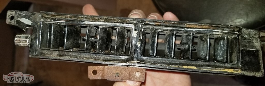
They Say the vents for the 69 Chevelle with AC are not being reproduced.
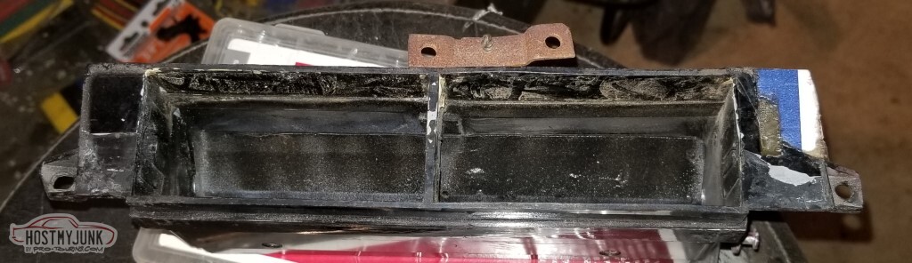
They Say you wouldn't be able to get this housing apart to replace them even if they were.
They're right, of course. But... if you're careful, you can use a dremel to cut away the seam where the front and back parts of the housing were connected at the factory.
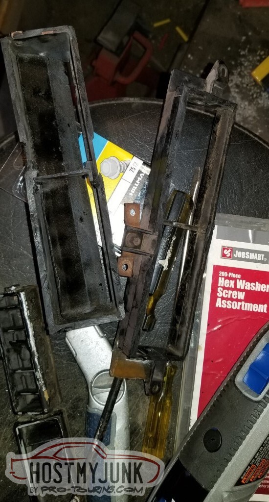
The Chevelle vents aren't being reproduced - that's correct - but the 69 Camaro and 69-76 Corvette ones have the Exact Same Dimensions. (OER 748614)
And really... these are horrible.
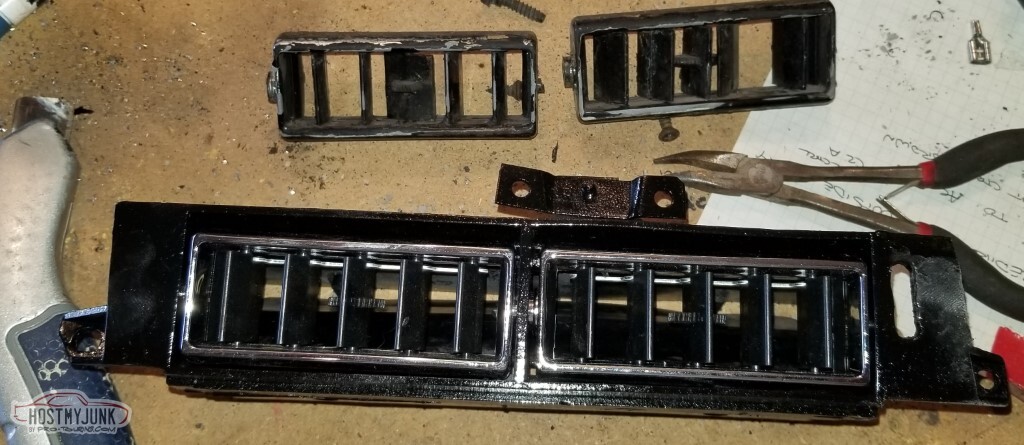
So a quick pass to try and fix the broken carrier (cardboard as a pattern, fiberglass resin over that):
A quick test fit:
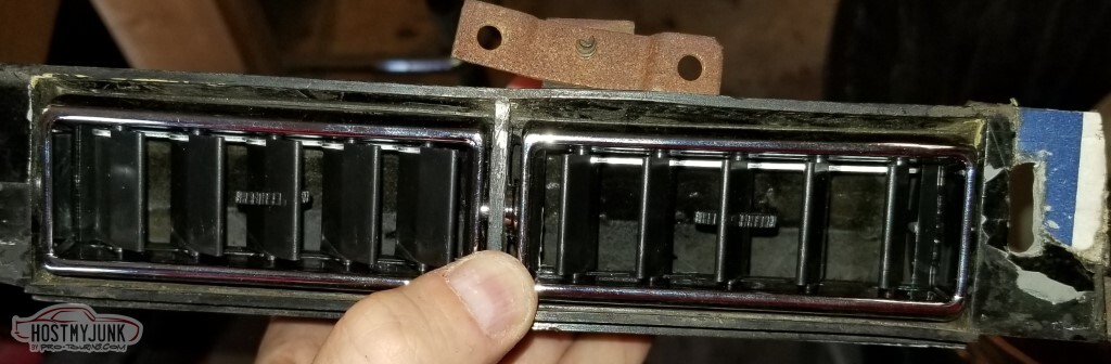
Paint, and it becomes hard to believe we started from the same place.
Also need to finish the cleanup on the AC controls.
Start with some black "low acid fade resistant" posterboard:
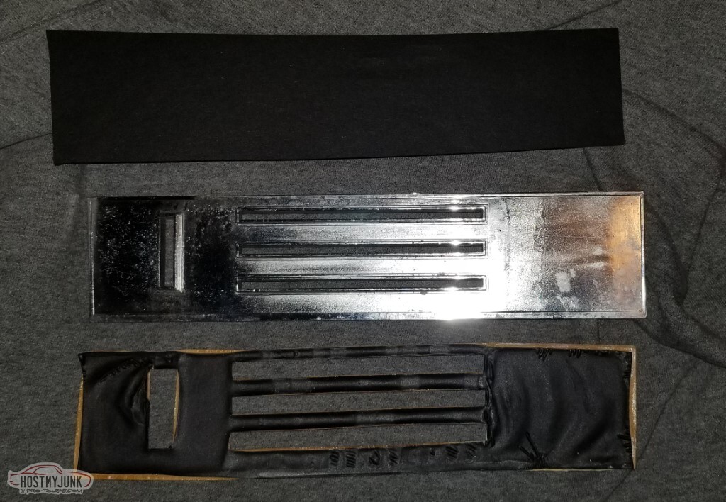
A bit of cutting, and you've got a heck of a before-and-after:
I finished up the pedal switches. The clutch safety switch ended up in a really convenient-to-attach place:
The other switches seem to be in decent places and are out of the way. Now to start the car, you have to press the clutch like on a real car!
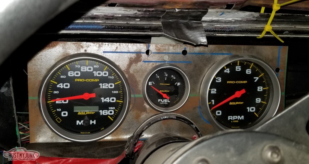
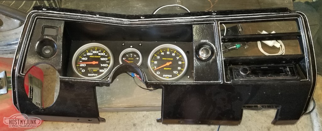
The dashboard is coming together. The gauges fit nicely in the housing and I've got all the indicators I need (and maybe one I don't -- the one bottom right of the speedometer is the cruise control, and I'm not seeing where I'm going to get the "yes, you're in cruise" signal)
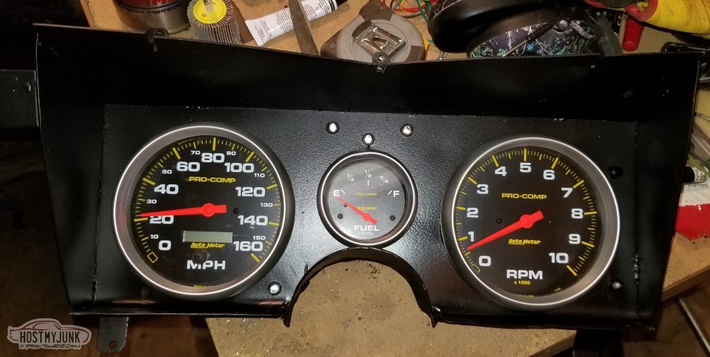
With the gauges in the housing (along with the radio):
I thought I was getting close on the AC box. It's not perfect, but used the last of the gloss black to look for imperfections (found some!)
More sanding, cleanup, etc., and then a coat of the "charcoal" paint I'd bought for this.
Yeah, this is not the color I anticipated. Will look for a better match to the factory color.
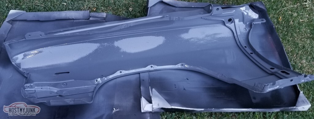
I went ahead and cleaned up the driver's fender for paint on the inside:
Predictably enough, I found crappy repair and rust.
I fixed the rust with a second crappy repair:
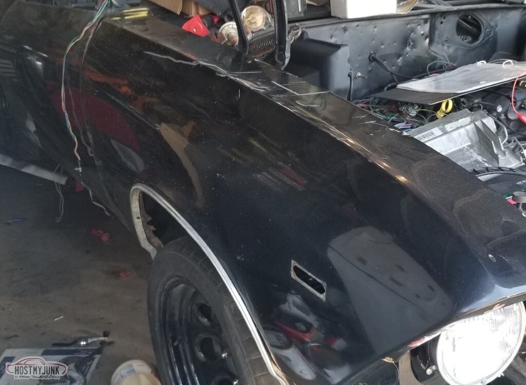
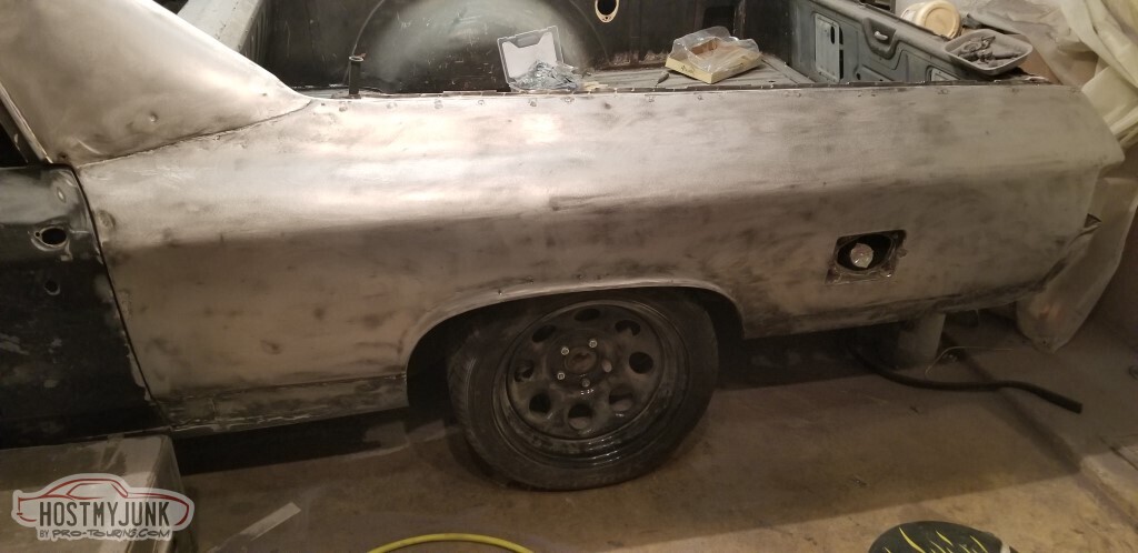
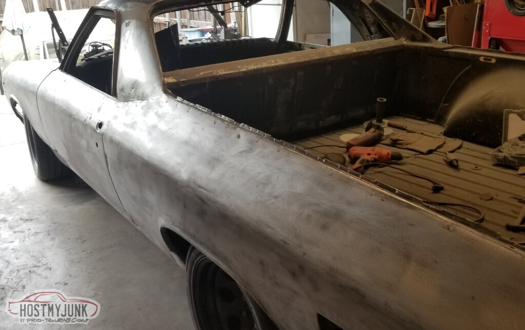
Painted and mounted the fender (even used shims!) - this should be pretty close to its final location. I'm not sure why the door edge looks like it's got a bend in it like that.
It's very pretty, in areas that won't typically be seen:
Got the parking lights taken care of. Unfortunately the gaskets I made are much thinner than the original gaskets, so the original screws won't torque down. Minor concern that it'll put the lens too close to the bulb and melt things.
I also handled the electrical to connect the parking lights:
Unfortunately I used the wrong ends for that connector so it all had to come back apart. It's a little sad, those were outstanding crimps:
I have a concern about mounting the flashing security LED and the light sensor. It looks like there's room behind of the speaker ahead of the pad, but that'll conflict with the AC vent.
Reckon the next up is to try and get a better tune on this thing - it's running extremely rich; I don't know what sort of tune they had on it when I got it but from a quick review, their VE table is very different from the stocker I found on the internet. Means I'll have to remember how to do this (read: learn how to do it).
-
05-18-2021 #89
Rat Pack Member

- Join Date
- Aug 2002
- Location
- Waleska Ga.
- Posts
- 2,711
Nice build thread!
Keep up the good work!
We used some of the same parts.
it cool to see a different approach with them .David Sloan
If youre suggesting sending men with weapons of war to take my weapons of war,then Im fairly certain thats whats called an act of war and the definition of tyranny.which coincidentally is the reason for the second amendment to begin with!
https://www.pro-touring.com/showthre...ght=fun+camaro
https://www.pro-touring.com/threads/...lcamino-build!
3 Days Ago #90
-ɹoʇɐɹǝpoW-
- Join Date
- Jul 2002
- Location
- Mesquite, TX
- Posts
- 4,928
Did not intend for additions to be THIS much slower.
The AC box held together this time!
The wires pass underneath it freely in that channel too - bolt it up and call it good!
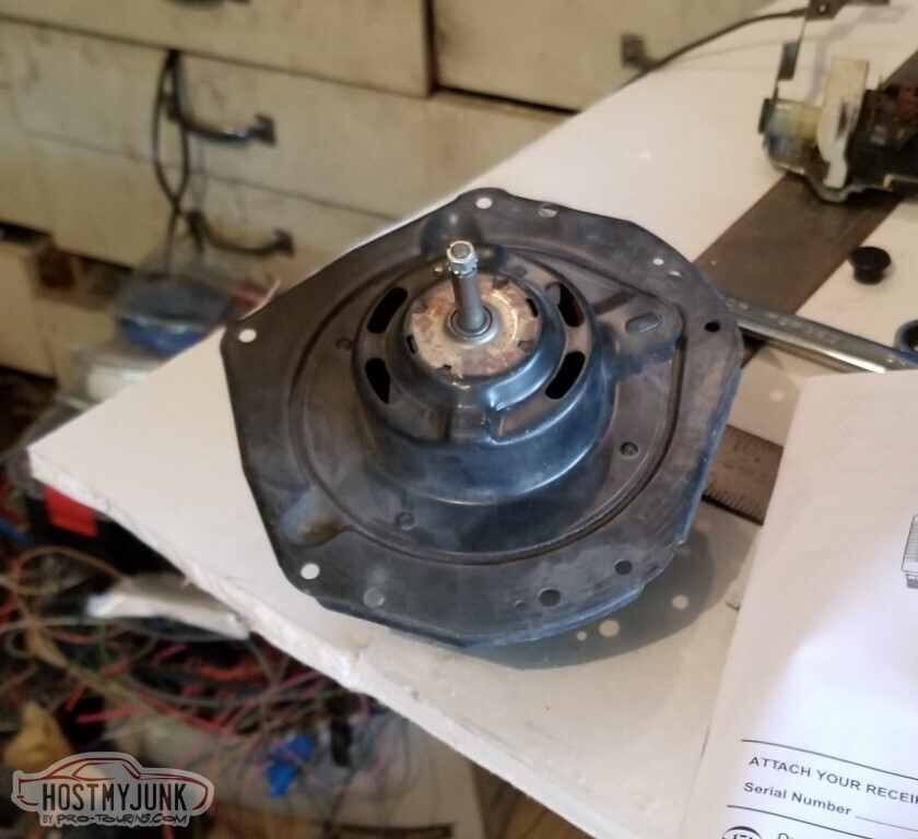
Begin FOUR DAYS of looking for where I put the metal squirrel cage fan.
It was here in the garage, I've put it somewhere "clever".
Found the spare AC box, it's got a plastic fan but it's damaged.
(No, the metal one was in a box in the attic. That's not clever at all.)
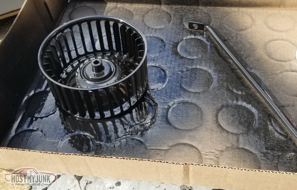
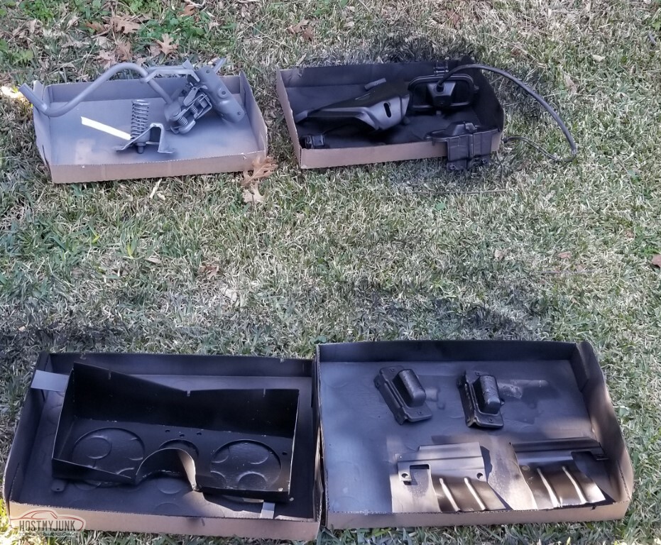
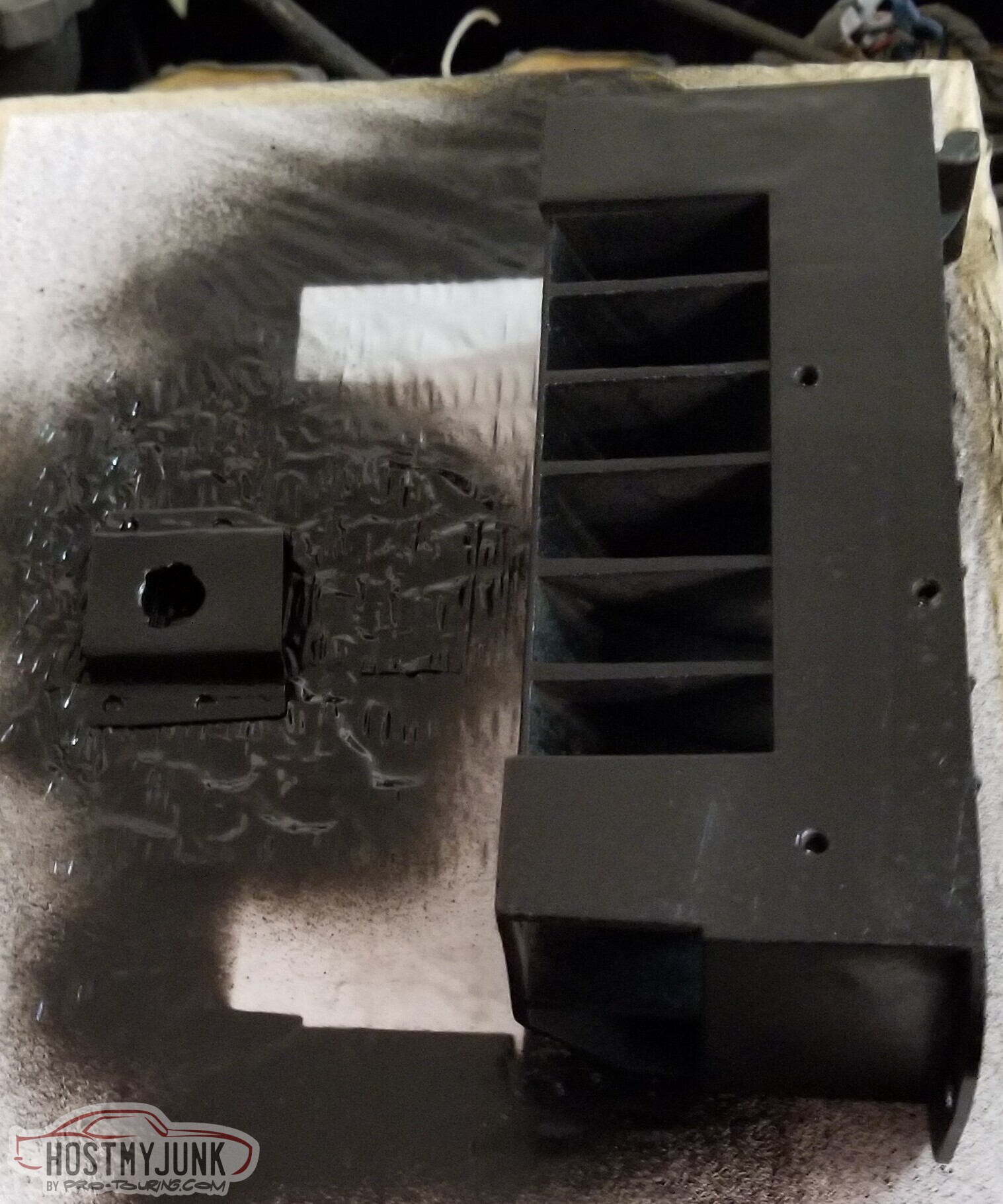
Sandblast and paint. Let's make it pretty before we put it where nobody will see it.
(Not pictured: The fan bottoms out in the housing. Where did I put the spacer? At least I found that where I expected)
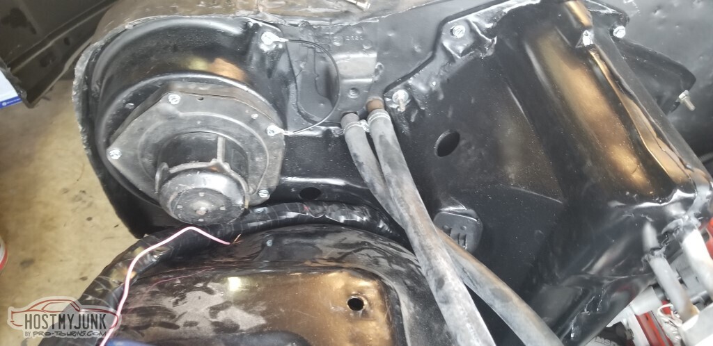
With the AC box mounted and the fan attached, I can clean up the pass fender and get it painted on the inside too. So I did.
And I took no photos.
It was the same as the driver's: rust, bad repairs, now additional bad repairs.
It lines up... poorly.
This is with a big stack of shims at the top AND at the bottom, and it's still not right.
Even after additional finagling. Also it's too far forward at the bottom.
I expect I'll be taking this back off for additional work.
(also I can't run a bracket to the core support to help hold the computer in place as it tucks up inside this rather than being accessible.)
I put the header panel on. It fit, mostly, but the car is slightly too large for the garage -- I have to squeeze past the nose to unlock the door, and this sticks out too far... so I've pulled it back off. It needed cleaned up on the inside anyway.
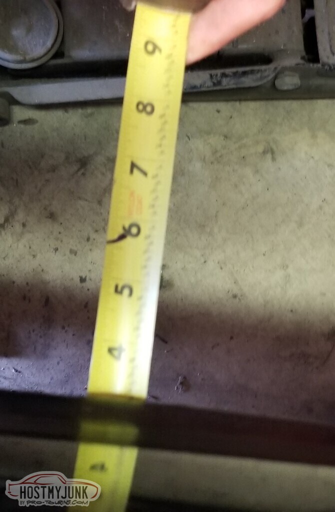
As I lay on my back trying to get the fender to line up better, I happened to have looked back towards the back of the car and was struck by how much room for more tire there was!
And it's true - there's about 3 inches from the outer edge of the pass rear tire to the outside of the fenderwell.
Unfortunately that doesn't hold true for the driver's side: the body is not square to the frame. So I loosened all the body mount bolts, and tried to pry the body over. That accomplished nothing.
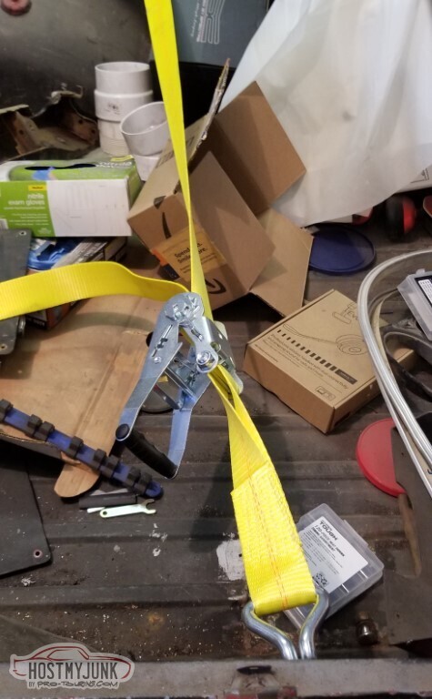
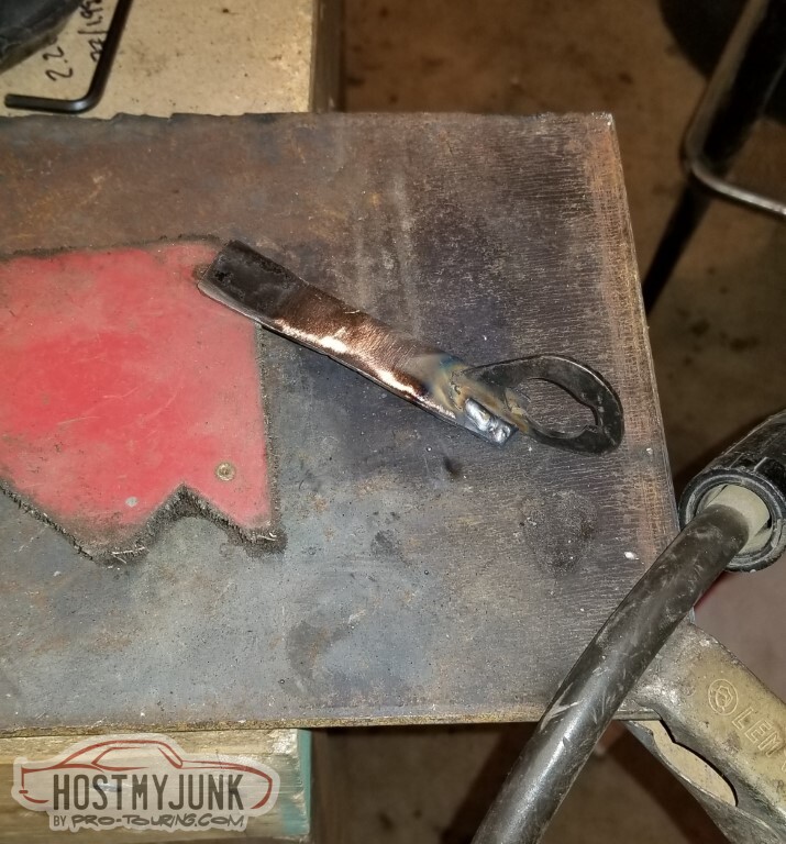
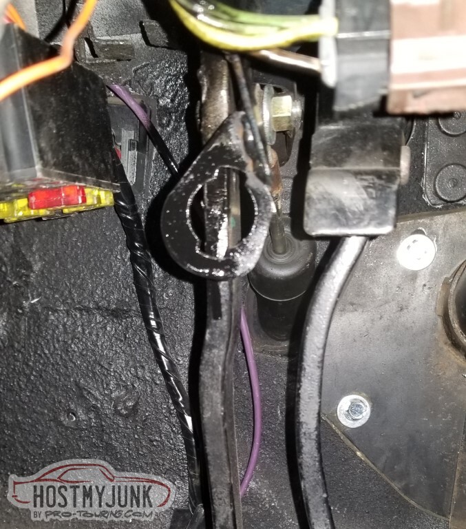
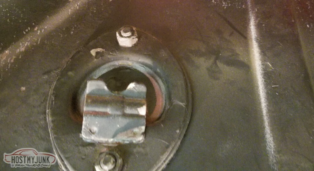
I've got a ratchet strap, what on the body can I attach to to pull against?
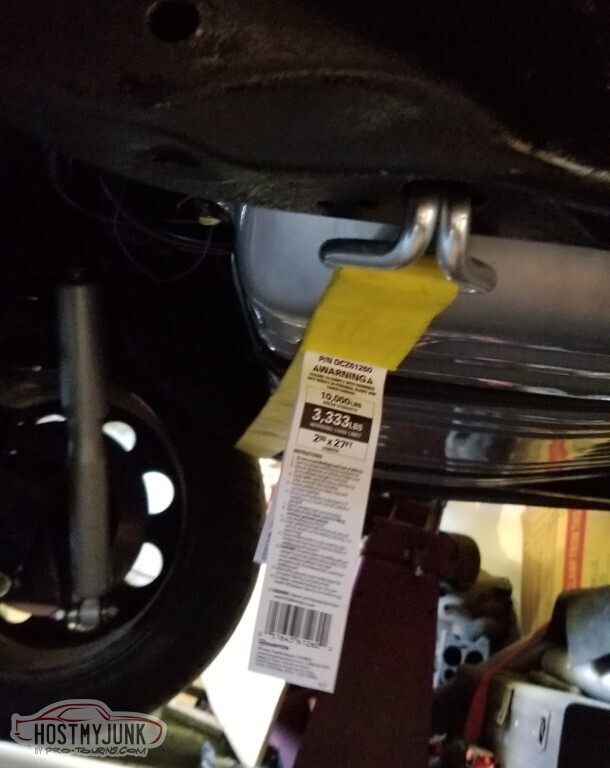
Maybe this beefy tie-down ring in the bed? Wrap it around, so it's pulling the frame that way.
Yeah, raise your hand if you see what's coming.
And now I need to repair the tie-down ring, and the body hasn't moved at all.
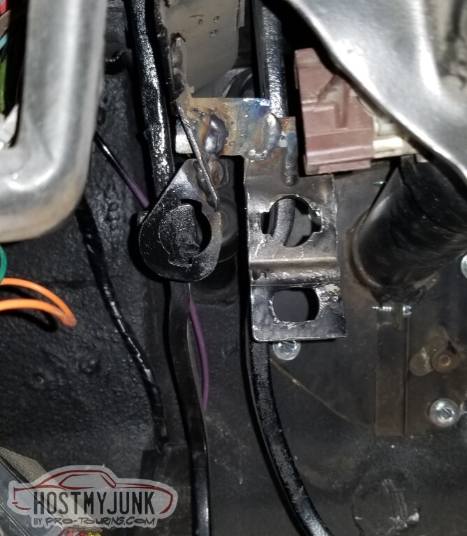
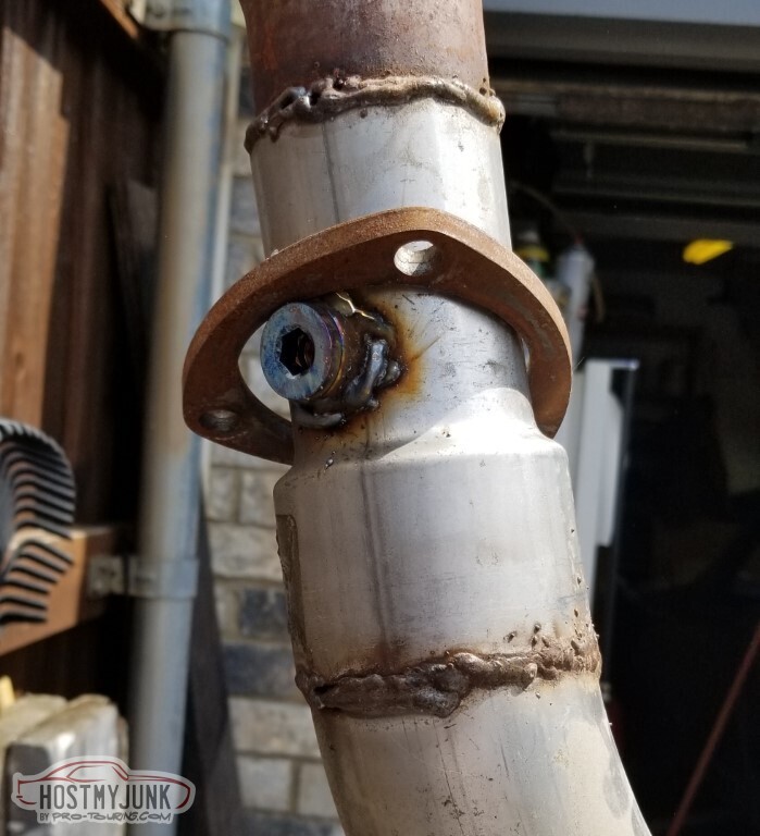
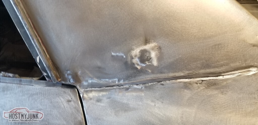
I had realized that I don't have an *accessible* bung for the wideband O2 sensor - the front one on the driver's header is too close to the frame to thread anything into.
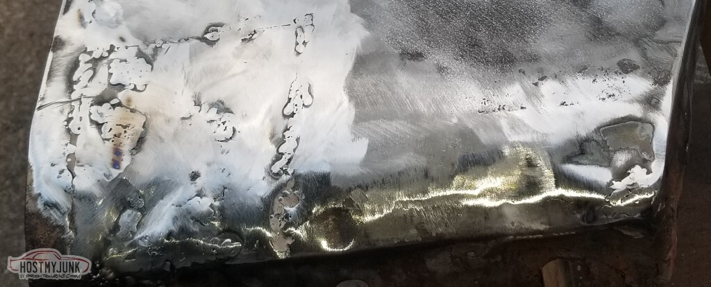
Added a new bung here, and as you can tell, I wasn't replaced with an alien replicant with some skill at welding (so I guess that's good news?)
3 Days Ago #91
-ɹoʇɐɹǝpoW-
- Join Date
- Jul 2002
- Location
- Mesquite, TX
- Posts
- 4,928
Left off yesterday with the tires not lining up in the wheelwell - everything offset towards the driver's side.
Tried ratchet-strap from various places underneath to other places underneath and gained maybe a quarter inch.
Got frustrated.
Bought a tool.
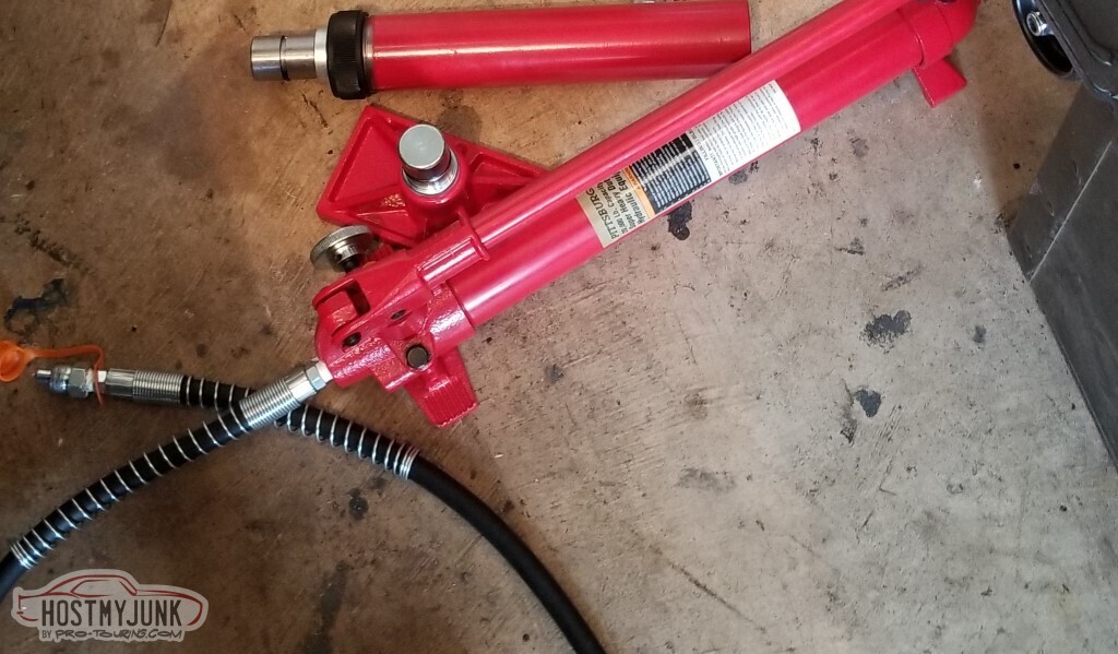
This thing MOVED the body. It made it clear, however, that I was barking up the wrong tree - when the body mounts don't line up with the frame, you know it's in the wrong place.
Yeah, I'm an idiot.
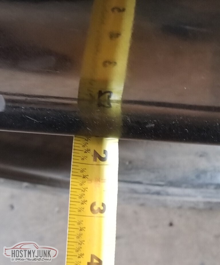
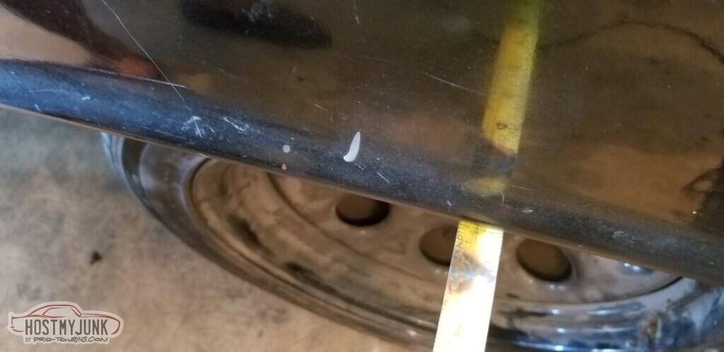
The adjustable UCAs can move the tires over. With that knowledge, I used the inner edge of the tire to the frame as a guide.
This tool also moved the body back though.
And now I'm at about 2 3/8 on each side.
Time to start putting the inner AC box together. This thing was painted red at some point, and then poorly black over that. Let's clean it up and redo it.
I need one of these connectors.
Did get the underhood wires for the AC set up and wrapped. I think the relay goes here. At least... now it will.
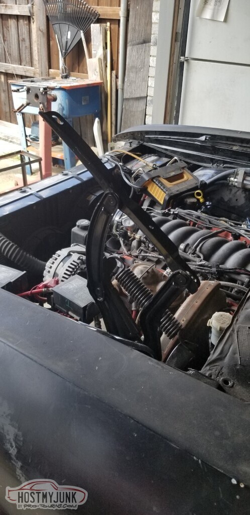
Assembled the hood hinges. This is probably another case of premature assembly but the springs were in the way.
Moved on to putting together the plug for the dashboard. It's going well enough, except for a few minor issues:
- White wire is tach. I don't have that wire, it's somewhere in a taped up bundle
- Black with white stripe is ground. Don't have that neither (although that's easy enough to correct)
- Also entirely possible that I'll have to do the workaround with the resistor and the +12 for a pull-up. Don't know yet.
3 Days Ago #92
 Registered User
- Join Date
- Nov 2006
- Location
- Mountain Springs, Texas
- Posts
- 4,498
Probably shouldn’t use the tire to check if the body is square on the frame. Camber due to front end alignment will move the top of the tire in and out a fair bit.
Don1969 Camaro - LSA 6L90E AME sub/IRS
1957 Buick Estate Wagon
1959 El Camino - Ironworks frame
1956 Cameo - full C5 suspension/drivetrain
1959 Apache Fleetside
3 Days Ago #93
-ɹoʇɐɹǝpoW-
- Join Date
- Jul 2002
- Location
- Mesquite, TX
- Posts
- 4,928
Things Were Done Wrong
That'd be a good alternate title: "Things that I have done that are probably done incorrectly".
Realized last time that I don't have a wire for the tach, also that I don't have the "you're in cruise" wire.
Well, the wiring diagrams helped; they let me know that the tach wire goes from the PCM as circuit 121, Red #10 not to the dash -- that comes over the serial
data - but to the traction control (which I don't have), and that the "cruise active" wire is PCM circuit 85, going to pin Red #13. Both wires are white and are pins F and G in connector C105.
Well, we have to start by removing this fender. I'll have to do some cleanup to try to get it to fit better anyway.
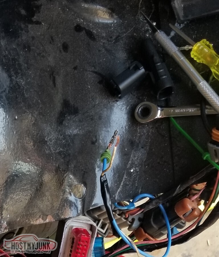
Here we have C105. I only have one of these wires - the tach wire to the traction control.
So I can just remove it from C105, go from the PCM directly to a wire heading into the cab.
I tried a weatherpak connector and made what looked like outstanding crimps. They weren't outstanding; no continuity between the weatherpak pin and the PCM pin 10. Also no continuity between it and PCM pin 13... and when I went to pull it back apart, the weatherpak pin just pulled right off.
And then I realized that what I had was not the tach wire, it was the cruise enable, and I'd cut the C105 pin off.
So - where is the tach wire from the PCM going, and what am I going to do about the cruise-is-on light wire?
As it sits here, I have pin 10 of the PCM (Tach out) connected to apparently nothing, and pin 13 (Cruise Indicator in) (not really) connected to a wire headed towards the cab. Quick fix: de-pin the PCM for both, so pin 10 is to the tach wire.
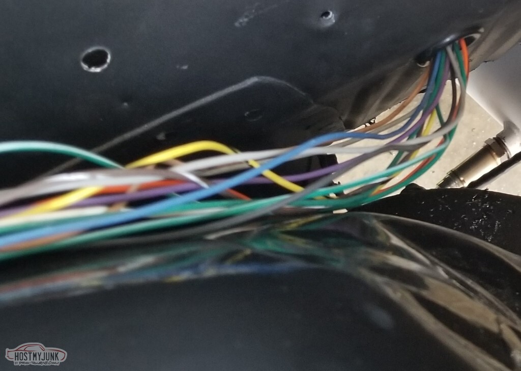
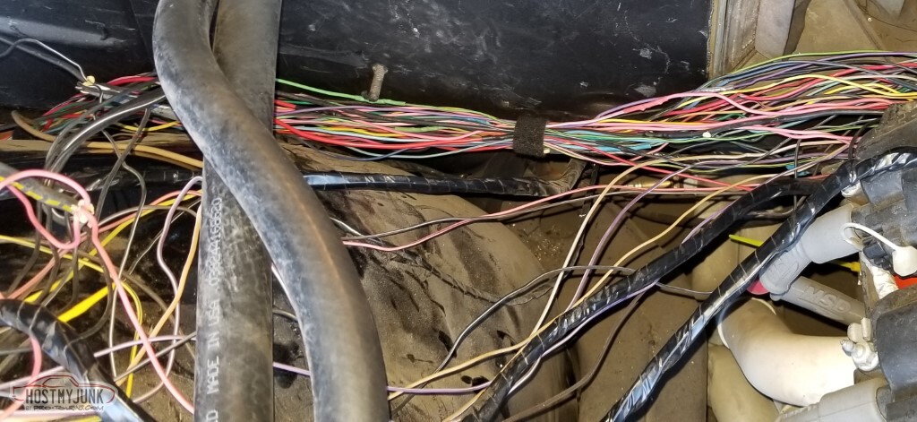
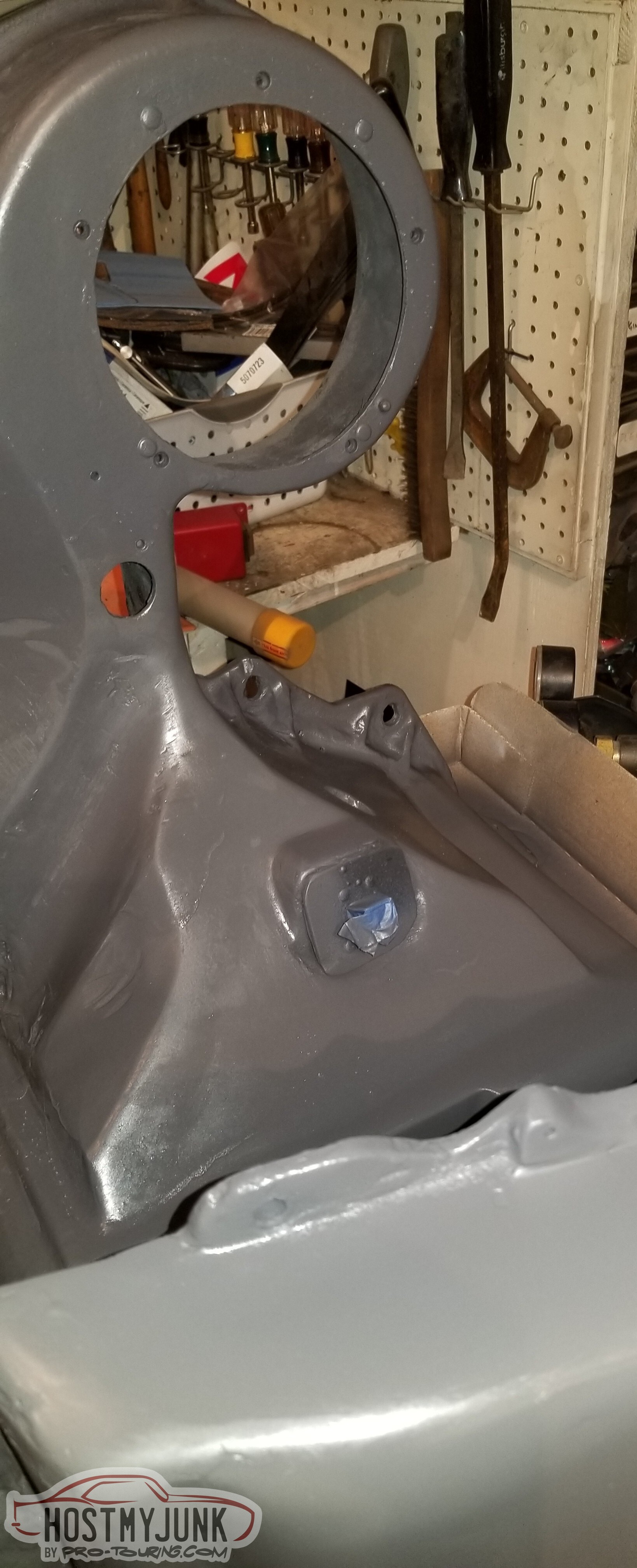
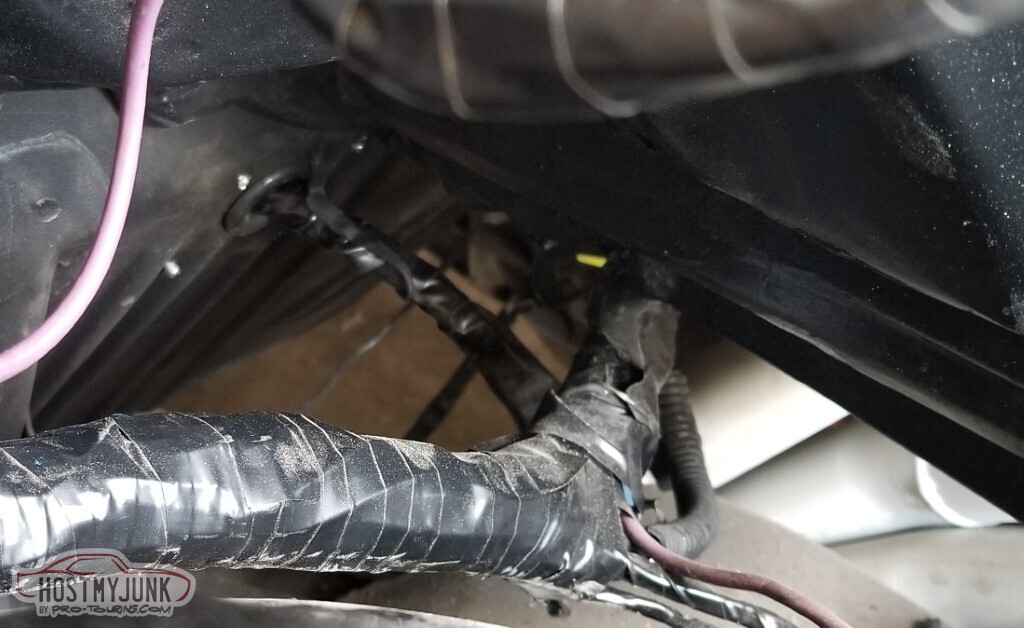
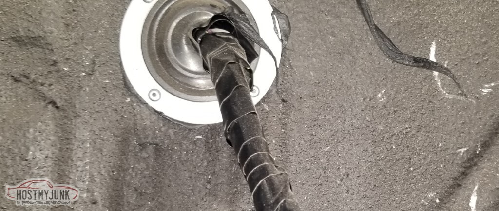
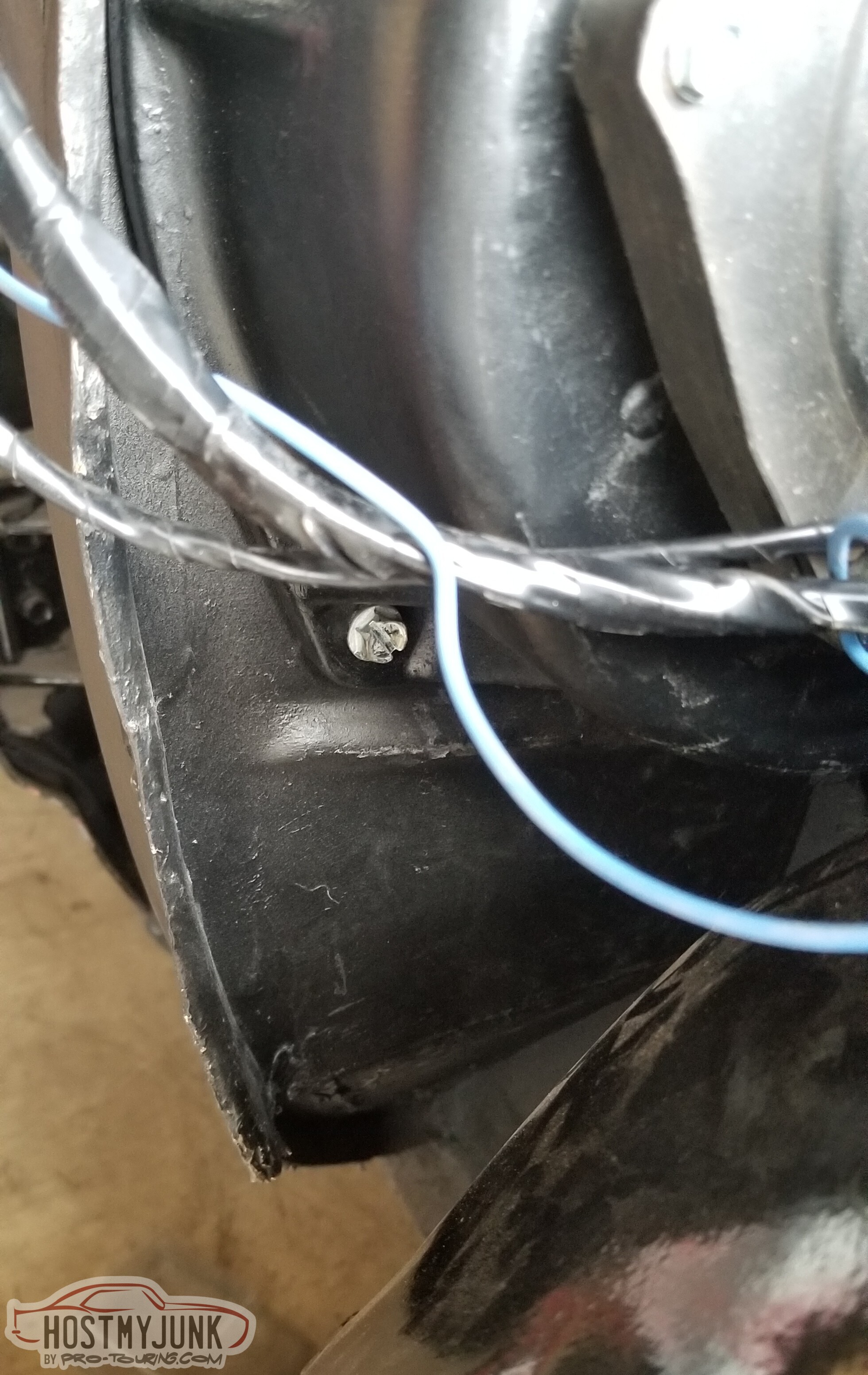
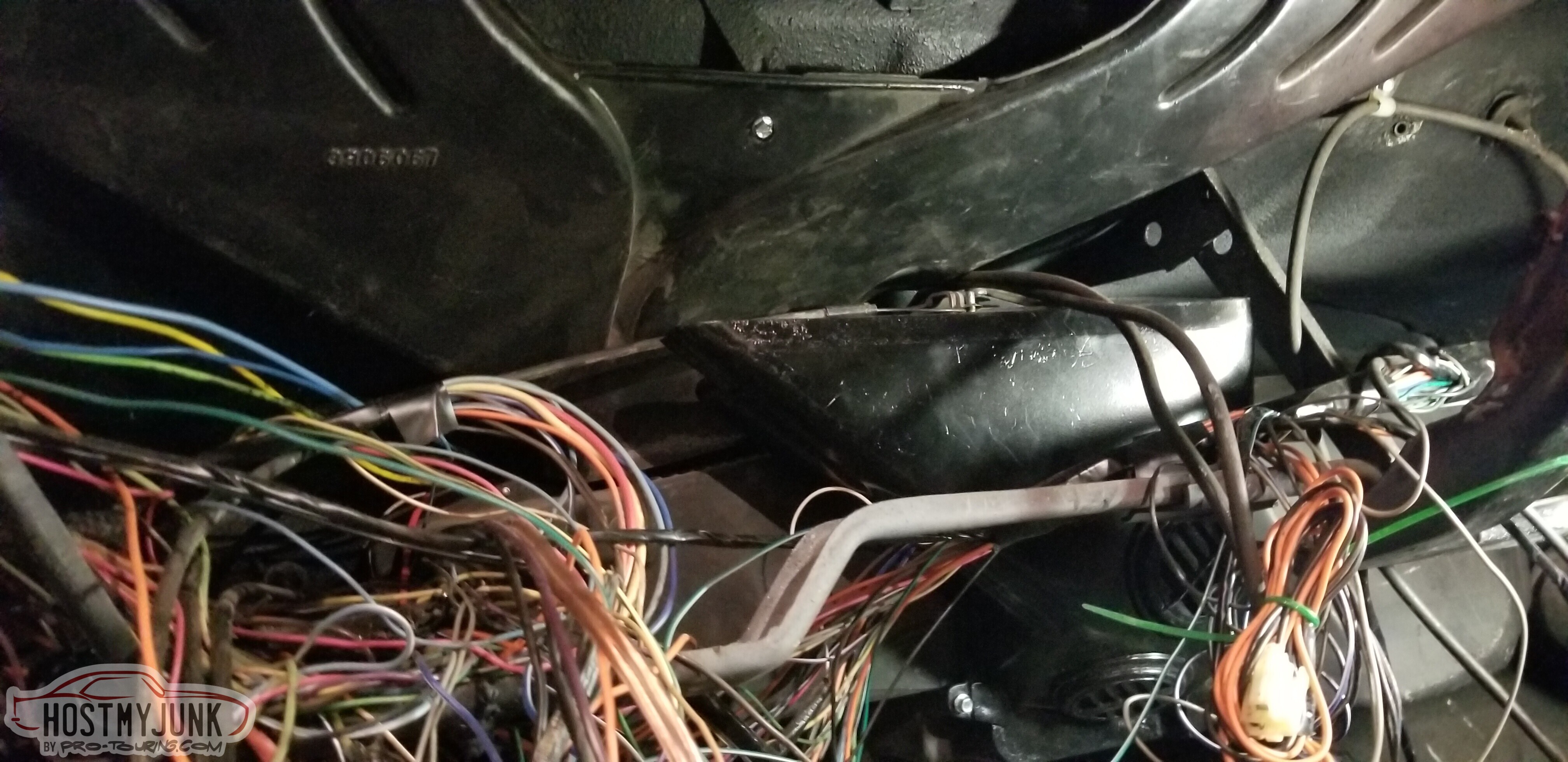
Back in the day, I put a grommet in the firewall and ran the wires for C220 and C230 through it. I've since realized that low on the firewall on the pass side invites a flood every time I drive in the rain, that location is unsuitable. I'll need to run them through the cowl sides. They're *probably* long enough. I'll also run the two new wires for the tach and the cruise indicator.
You can vaguely see the grommet and the wires.
The better seal on the inside still wouldn't be sufficient.
Of course, as part of this, I had to unwrap the wires. Again. Really would have preferred to not do this.
3 Days Ago #94
-ɹoʇɐɹǝpoW-
- Join Date
- Jul 2002
- Location
- Mesquite, TX
- Posts
- 4,928
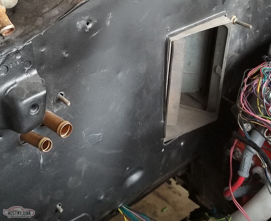
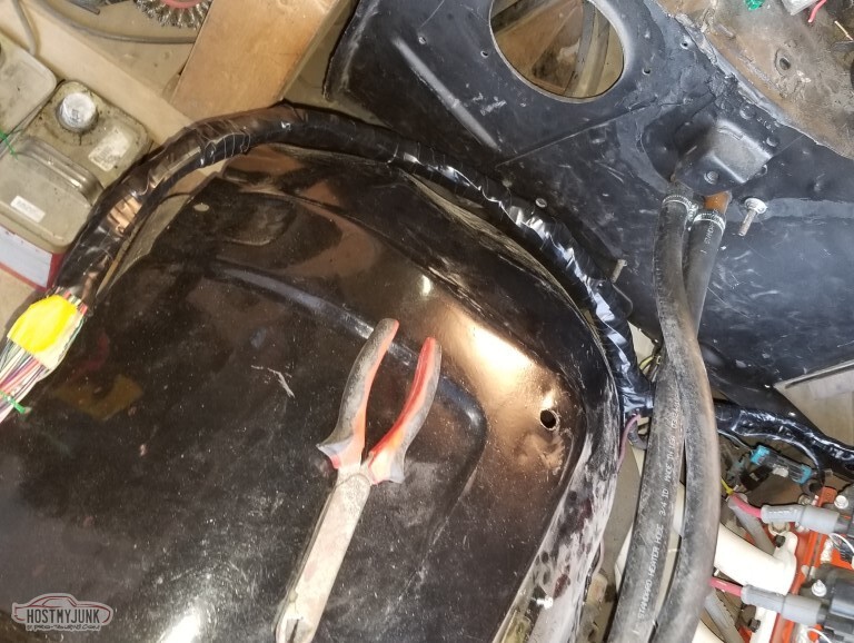
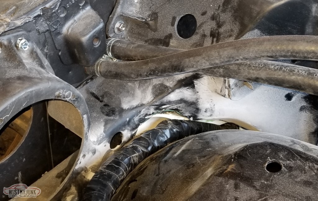
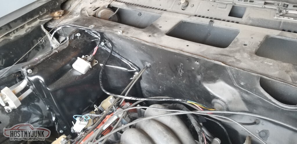
First off - the wires for C220 and C230 were running through the lower firewall at the pass floorboard. Realization that this is going to go really poorly every time I hit a puddle means the wires need to move.
Here's a good spot - it'll be protected from splashes and can run the wires through the side of the cowl.
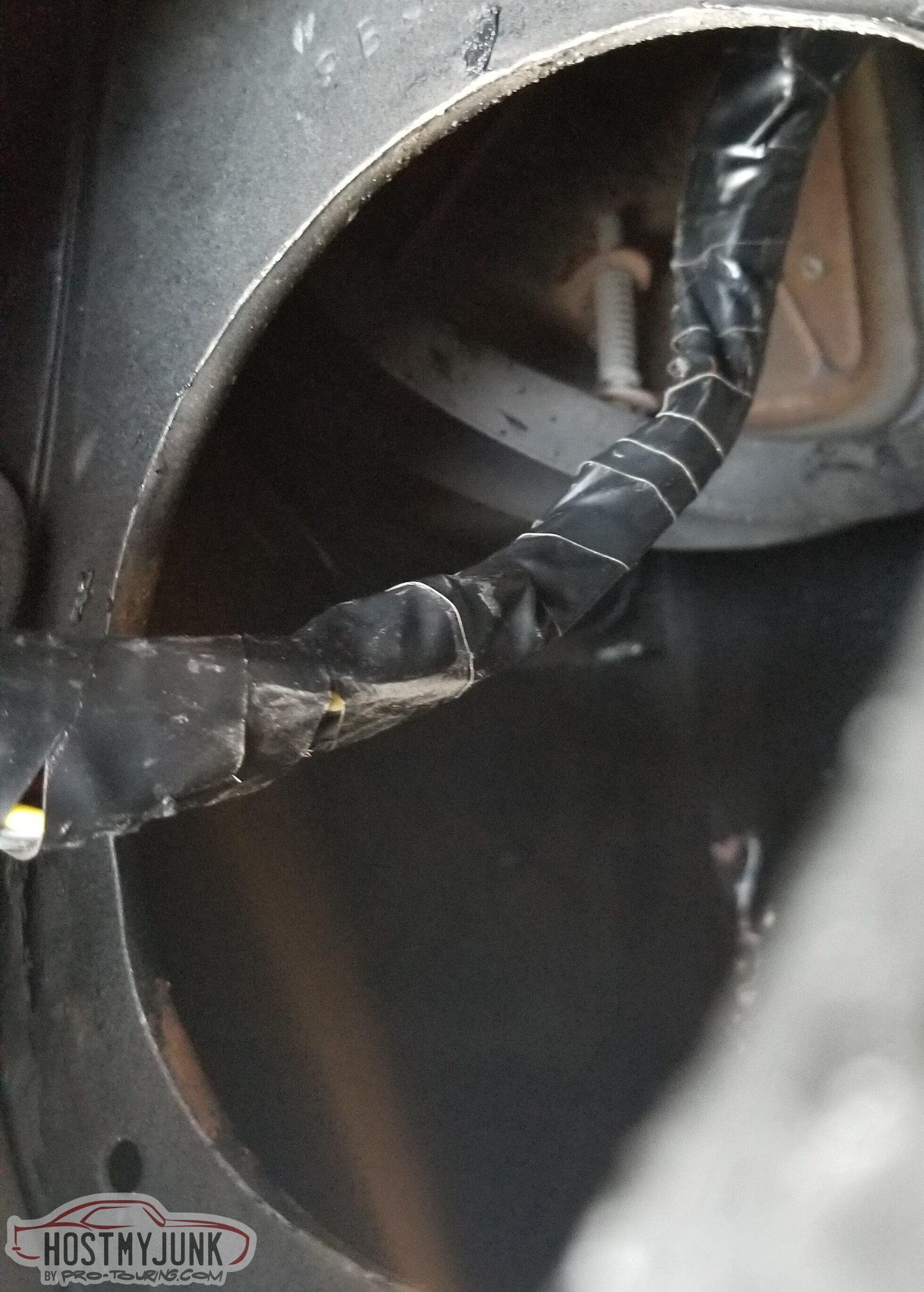
My first thought had the wires coming in and immediately making a hard left and coming through the inner edge of the cowl. Realized that that was maybe even worse of a place than the floorboard - the cowl is guaranteed to get a lot of water flowing across it in any rain.
Better to use the back edge of the cowl side for access.
This picture shows neither.
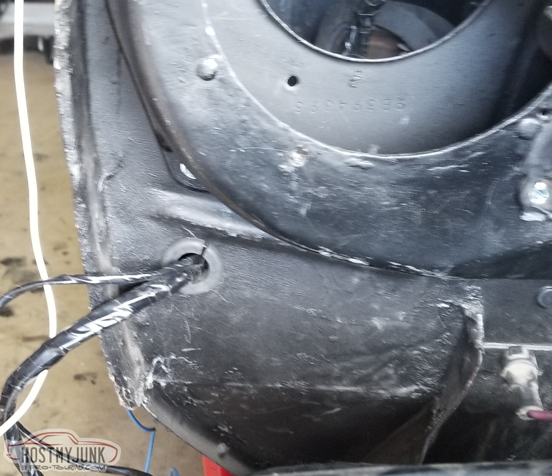
With the wires run through, here's the grommet. Added Strip-Calk to seal.
The small set of wrapped wires is a white and a blue wire, for the tach and the cruise indicator.
Unfortunately I am not sure which color I used for which - I *think* white is tach.
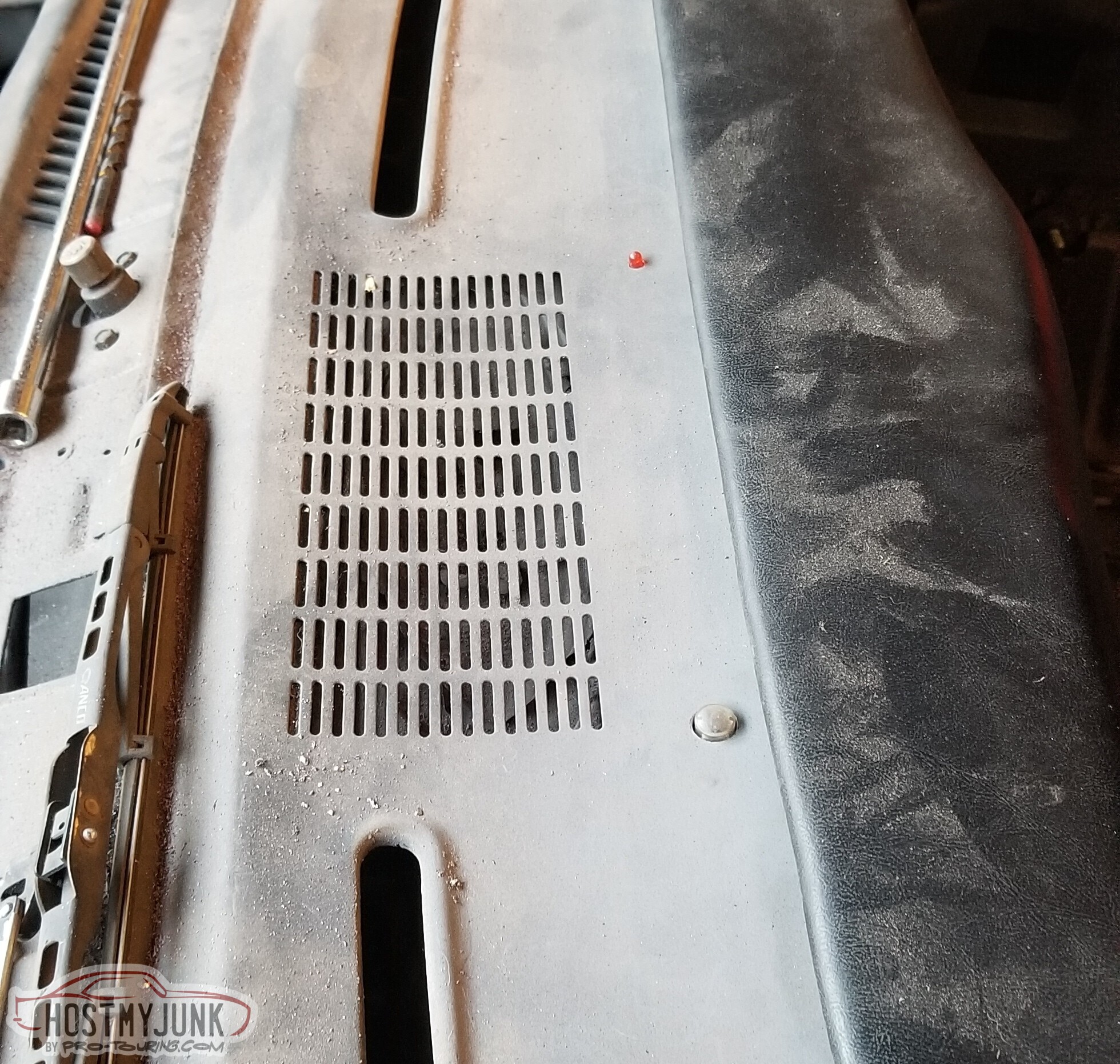
Added weatherstrip to the top of the defrost vent.
They Say that you shouldn't seal these. I did it anyway.
I bought a condensor - a Vintage Air 037030-OVR. It was 29.5" x 16", which matched what I measured the opening as.
Spoiler alert: Nowhere close to fitting.
Returned that, bought a different one - Vintage Air 037033 (24" x 12"). Still need to get the brackets set up.
Retried mounting the pass fender. It worked better this time.
Need to either adjust the front of the door "out" or add shims to the bottom mount. It's close though.
Quick paint on more things.
Defrost vent mounted. Wires are still strewn, need to clean that up.
I have created mounts for the ambient light sensor and the security LED. I REALLY hope these are in a good place.
And then onto the hard part.
New purchase.
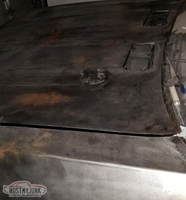
I *think* this is the last remaining task that I categorize as "really hard". I'm actually terrified of this task.
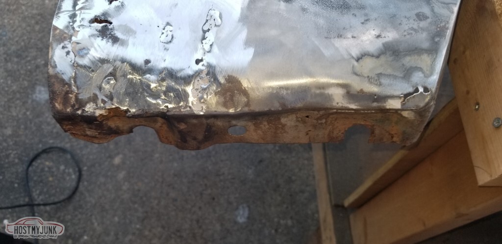
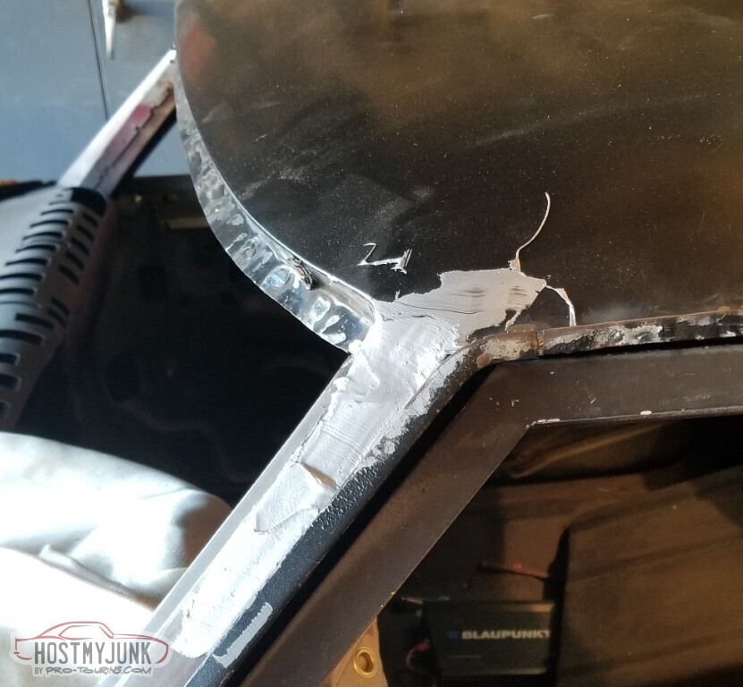
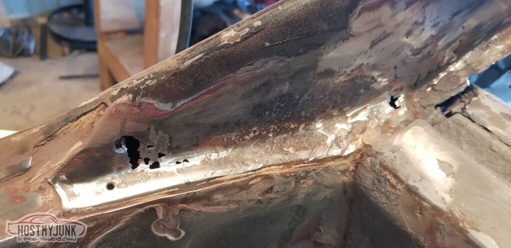
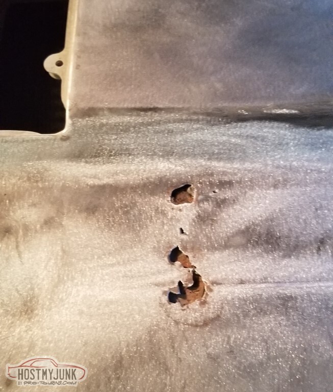
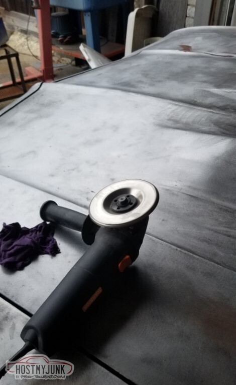
Cleaning the area at the edge of where it'll go with a wire wheel revealed oddly shiny metal.
Oh.
That's lead.
A torch works well to remove it.
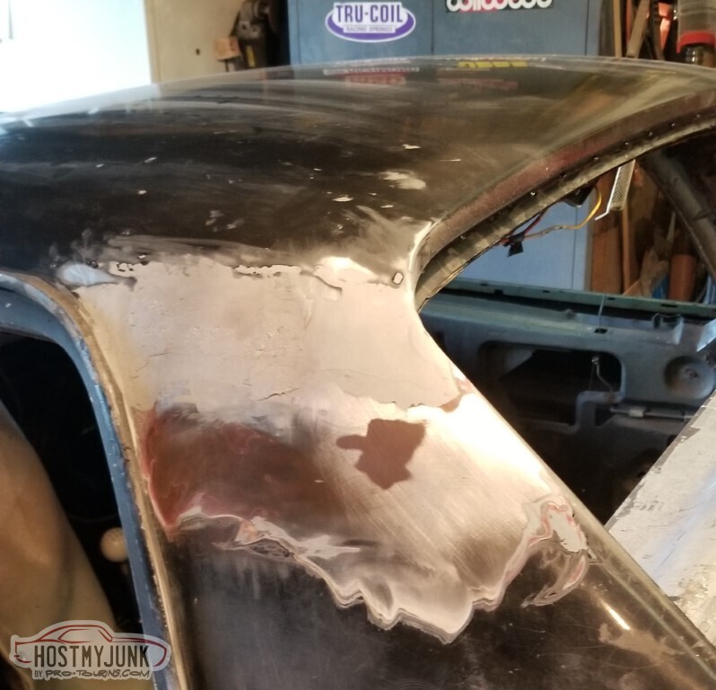
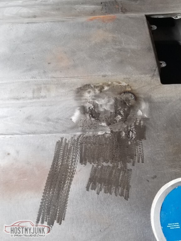
and fully cleaned up.
And again on the other side.
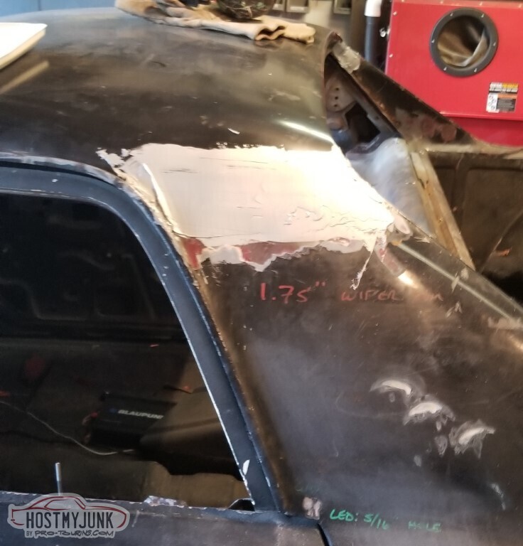
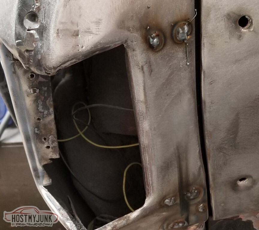
Did find that there was some half-assed rust repair on the windshield. I don't THINK I did this in the last round.
Doesn't matter anyway, this is all getting replaced with the new panel..
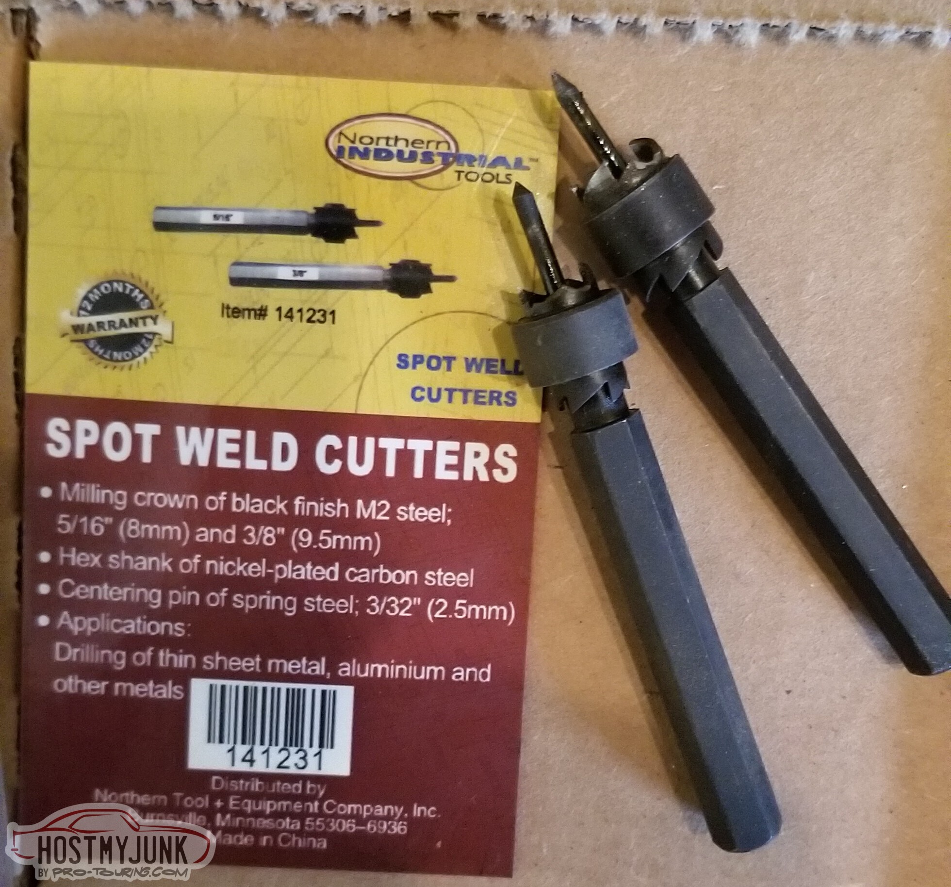
I had these.If you look closely, you'll see that both of them have broken teeth - one of them happened on the first spot weld.
I spent about twenty minutes trying to figure out where I'd put the first one after the second one also failed, and while I was searching I tried to come up with advertising copy for these.
The best I came up with was either "The quality goes in before the name... what's that? Oh. No, it doesn't." or "It makes good cutters or it gets the hose again".
Either way, an order of cheap spot weld cutters from the Kingdom of Bezos arrived the next day.
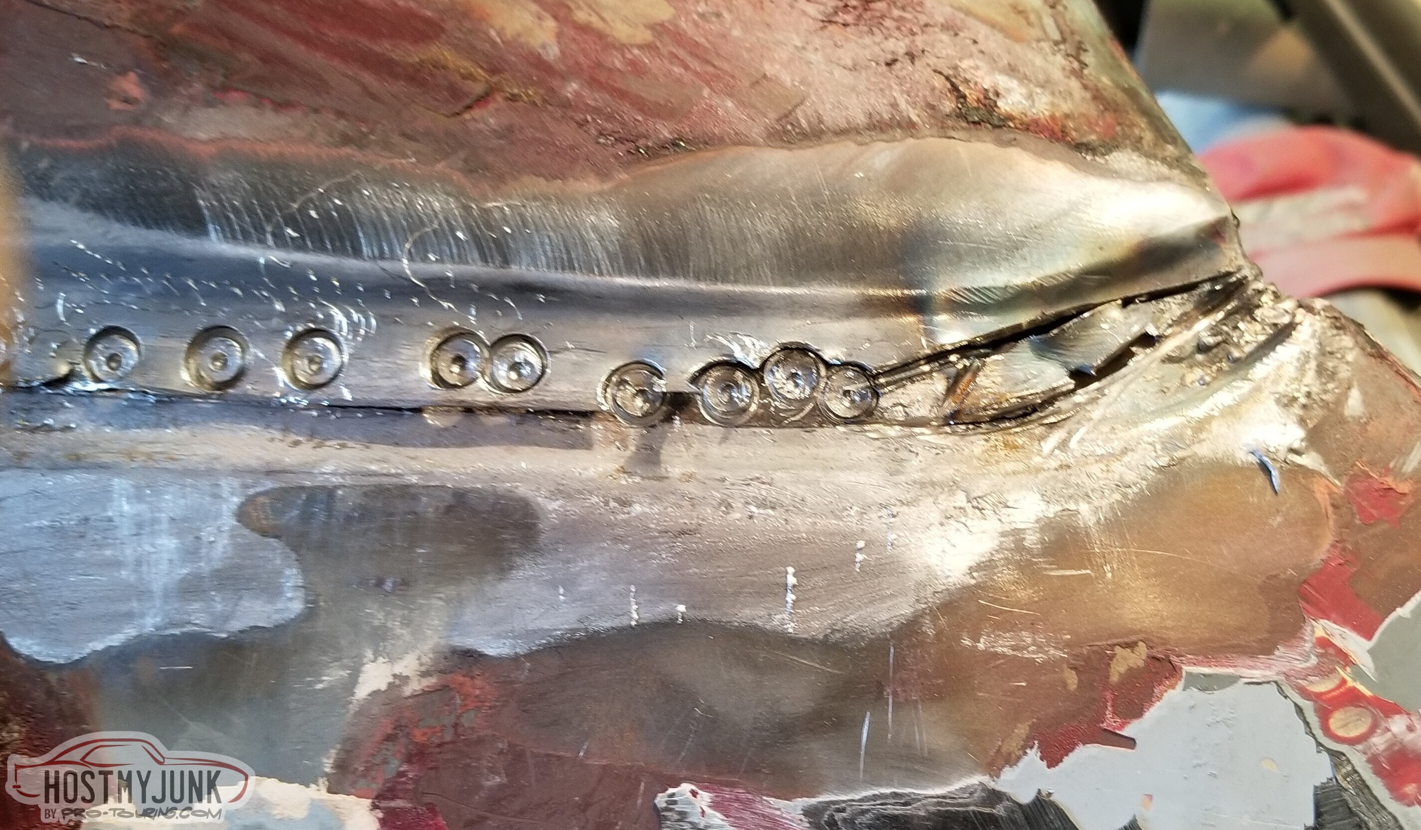
I have cut the weld beads incorrectly.
3 Days Ago #95
-ɹoʇɐɹǝpoW-
- Join Date
- Jul 2002
- Location
- Mesquite, TX
- Posts
- 4,928
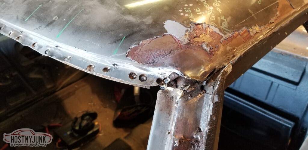
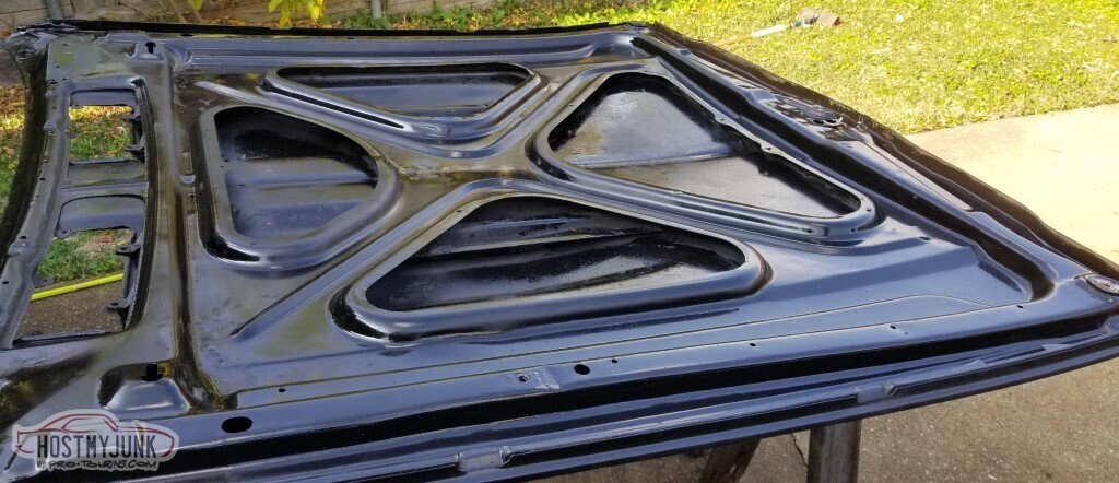
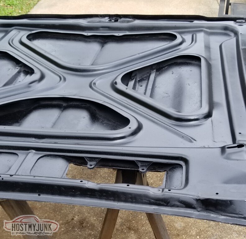
With the improved spot cutting bits, removal proceeded.
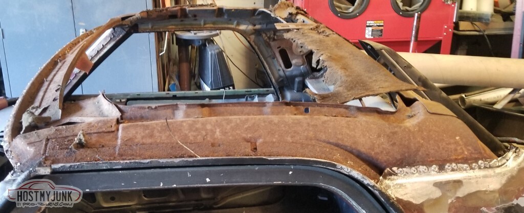
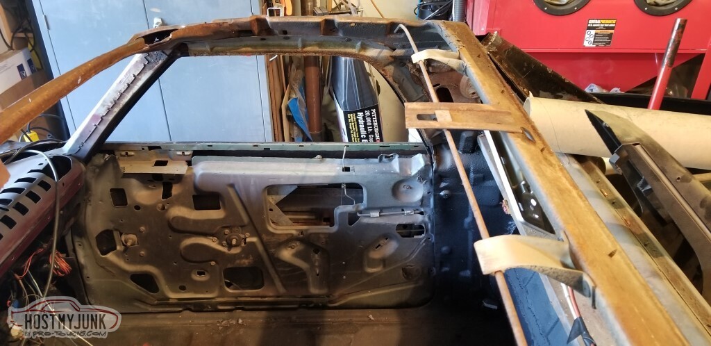
and then the roof fell off.
Saved for posterity? I don't know what I'm going to do with this.
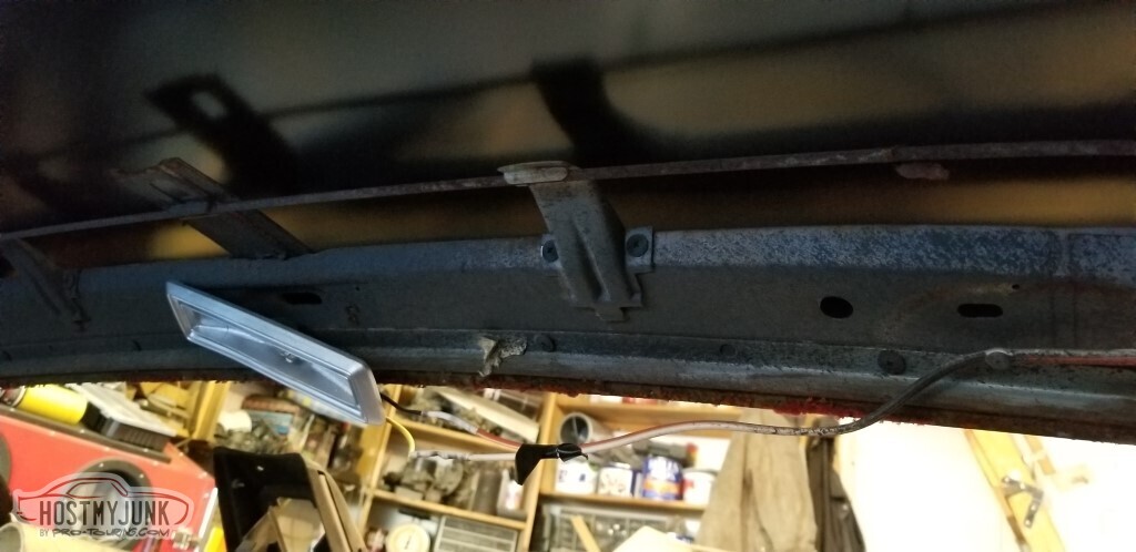
The braces are well seasoned.
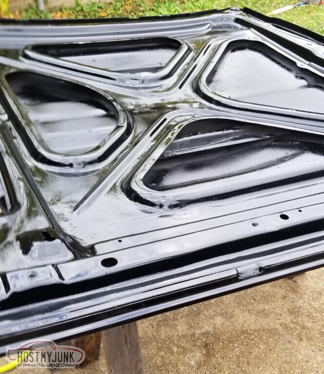
Also still have the remnants of the insulation.
Cleaned up. It looks like the headliner brace (right middle) had been cut to clear the sunroof. Reckon I'm going to need that.
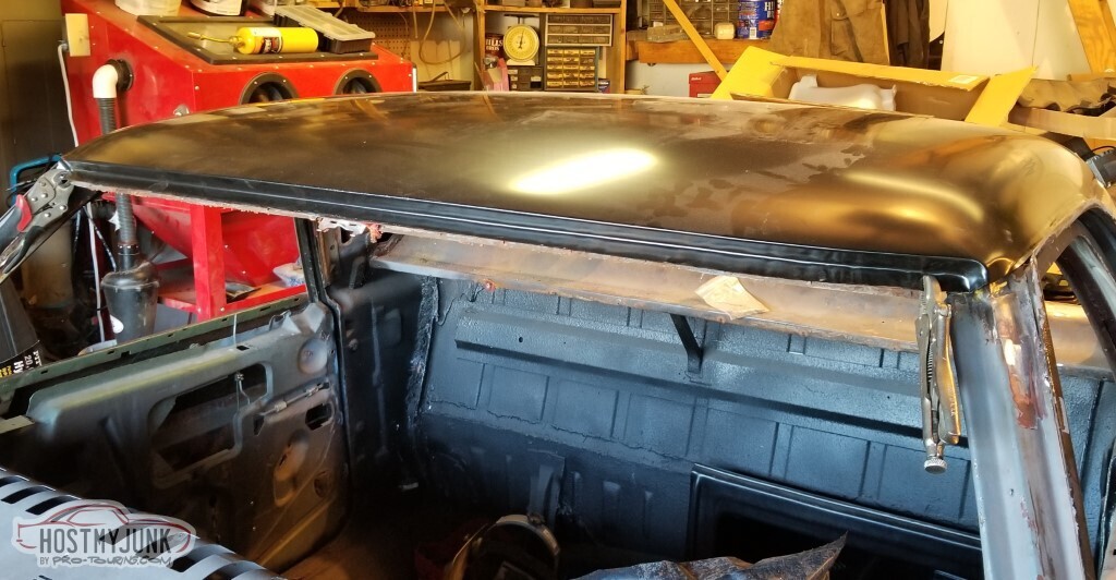
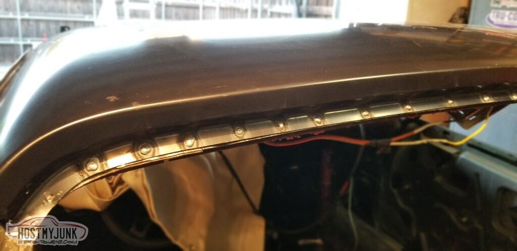
Test-fit the roof. This is how it clears the rear. It doesn't look like the back edge of the roof lines up well with the existing flange.
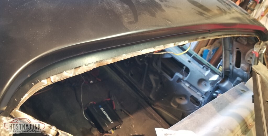
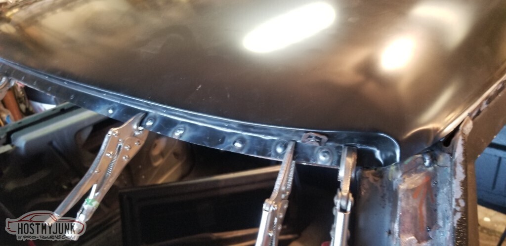
With more vice-grips it lines up much better - the flange comes up to meet the roof.
And the front edge works too.
Do need some repair on this side.
It fits pretty well.
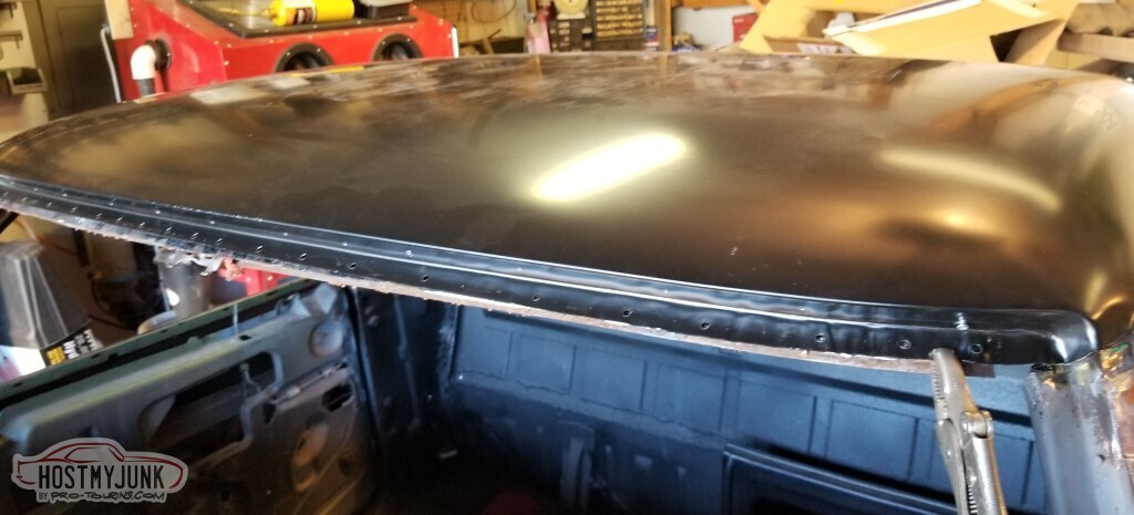
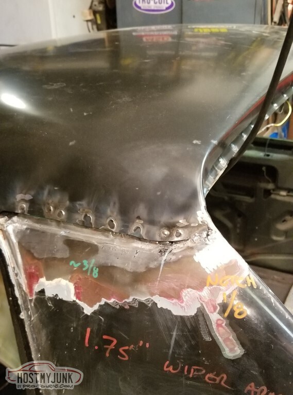
Punched the holes for the spot welds, and drilled for the windshield trim studs.
I ordered new braces to replace the missing headliner brace. This one came with, didn't realize that I needed to replace this one. Maybe I don't.
The rear brace is just fine, even though I got a new one. Also note that I coated the "hidden" part of all these braces with POR-15 (yes from that same can still).
And this came instead of a headliner brace. I don't know what this does, I don't know where it goes. It doesn't look long enough to really go here.
As a reminder, this is the remnant of what I need to replace. The unknown brace does not appear to be the same thing.
I'll have to call OPGI on Monday.
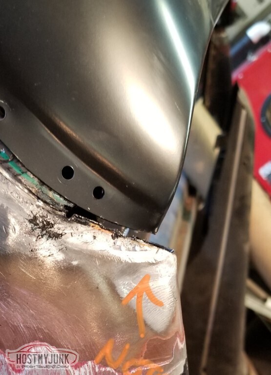
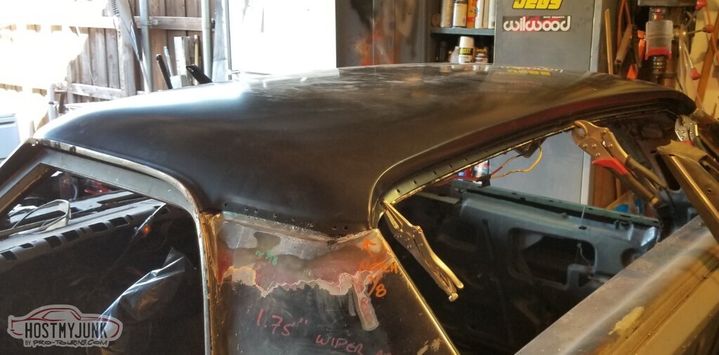
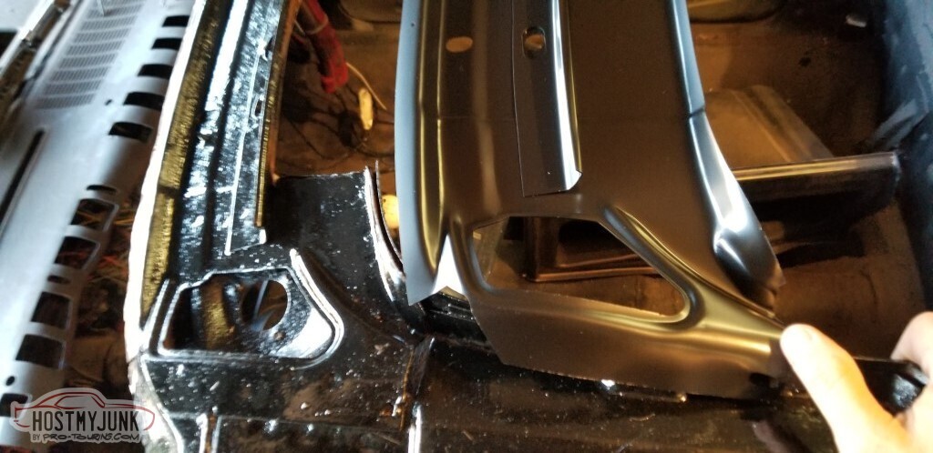
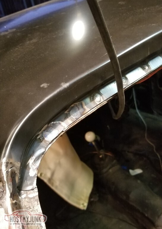
I do not quite like the way the driver's rear of the roof lines up with the B-pillar.
Passenger side is acceptable.
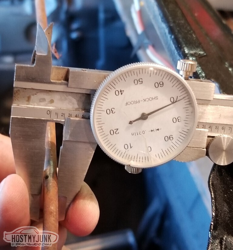
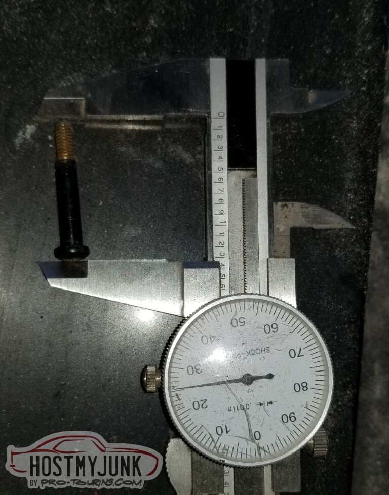
Also the new rods - while their shape does match the existing rod I have - are about .002 larger in diameter than the current one.. which means I'll need to expand the holes.
(ignore the actual number on the gauge; it's not .271)
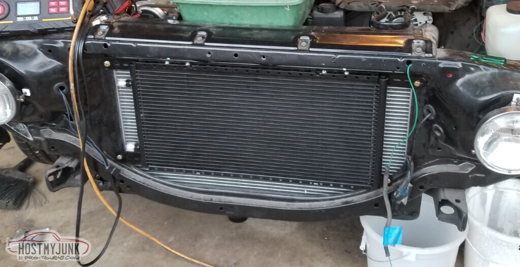
Also I mounted the AC condensor. This is not the final-final location, it needs to be moved away from the radiator a little.
I bought the paint for the dash top/dash face, the high-end seam sealer for the bed close-out panel, and the adhesive for the rear window from the local Sherwin-Williams Automotive. Since the high-build primer there was stupid expensive, I ordered some U-POL from Amazon.
Also we have The Plan for the interior. I need stock headliner, visors, sail panels, door panels, and carpet in dark grey. Unfortunately, that wasn't a factory color that year.
Carpet was always going to be custom - the larger tranny hump would prevent proper stock carpet. None of this is useful until I get the headliner brace handled.
3 Days Ago #96
-ɹoʇɐɹǝpoW-
- Join Date
- Jul 2002
- Location
- Mesquite, TX
- Posts
- 4,928
OPGI was not particularly helpful. They could just tell me that the kit contained front, rear, and middle braces.
I think the unknown "middle" brace is for a Chevelle (see this Chevelles.com thread with a pic).
Regardless - the set got returned. It does not appear that the middle brace I need is being reproduced, nor the equivalent for the longer-roofed vehicles.
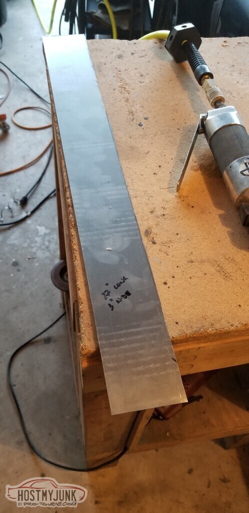
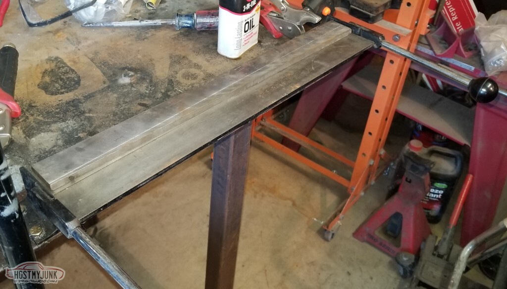
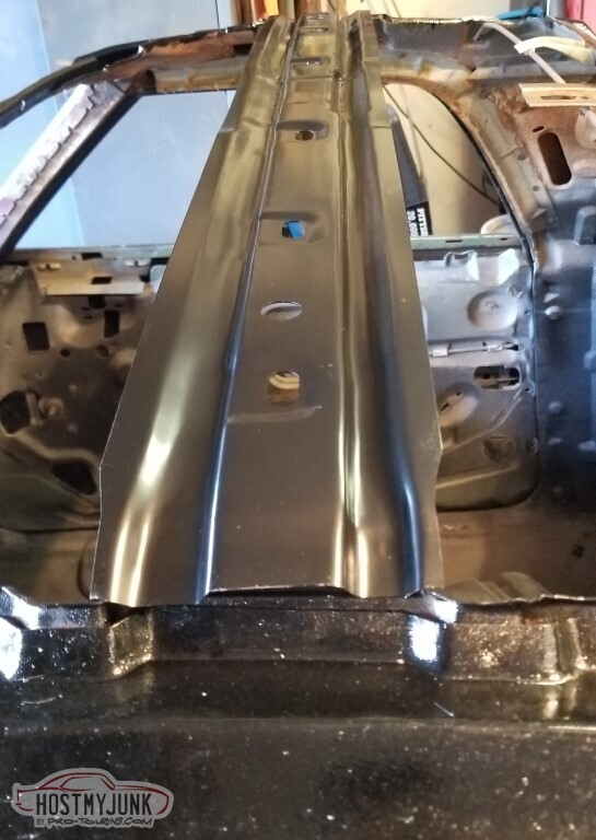
So the logical next step is to make my own. It ain't got to be pretty. Cut a sheet of 22ga (I'd have preferred 16 or 18ga but didn't have it big enough). That strip is 3" wide by 27" long.
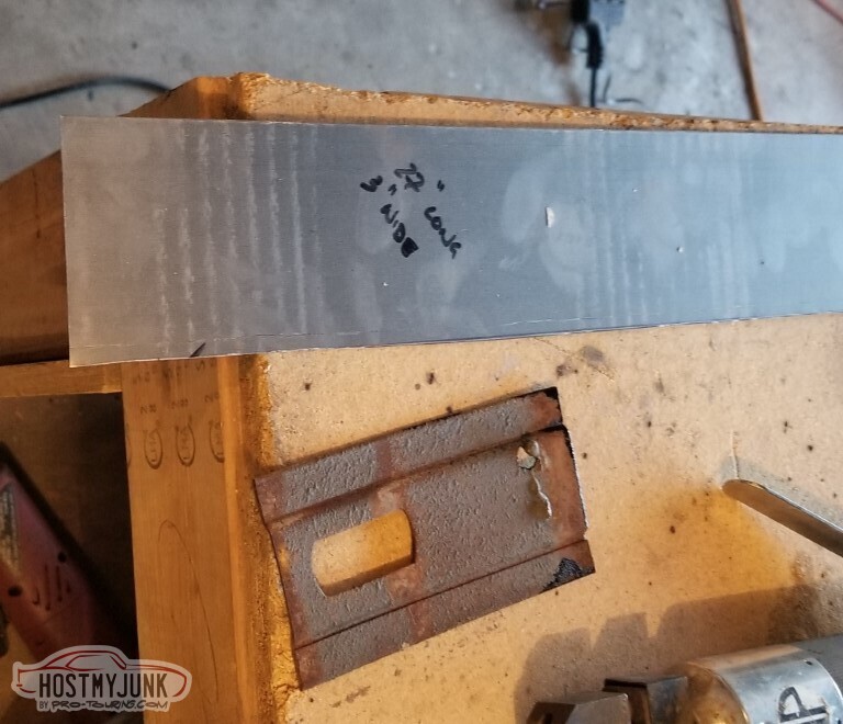
Cleaned up the edge a little with a file.
Used the flanging tool to put a nice bend on the edges to add some strength.
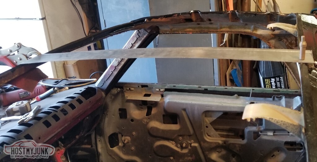
Test-fit.
Cleco at the back, front wraps around a flange.
This needed to have more of a bow to it.
Used the bow I had in each of the holes to identify the range that was valid for each of these clips.
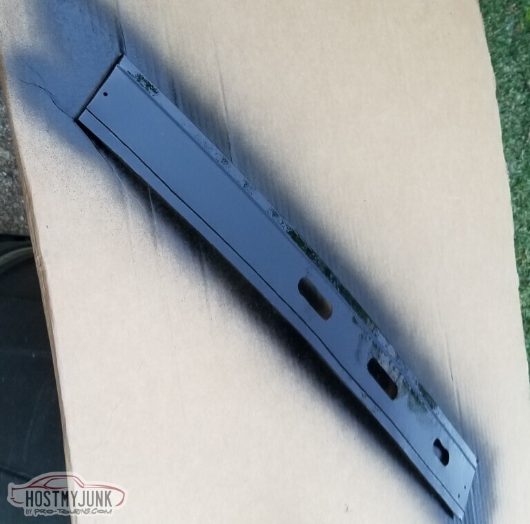
Paint, too.
Test-fit. Acceptable.
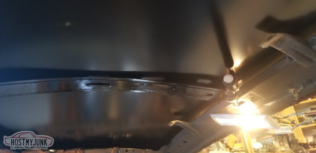
And then the welding starts.
Weld, weld, weld. Skip around so nothing overheats.
Grind the welds.
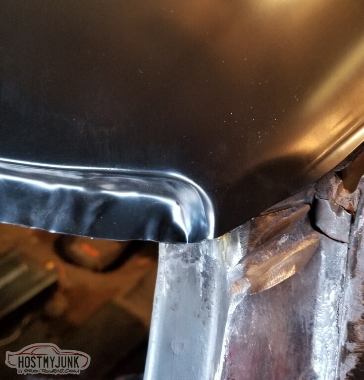
Also I cut a small bit of metal to match the back edge of the roof to the B-pillar and welded it in. This looks a lot better.
Started grinding the welds in the rear window area. Ran out of daylight, more to come.
3 Days Ago #97
-ɹoʇɐɹǝpoW-
- Join Date
- Jul 2002
- Location
- Mesquite, TX
- Posts
- 4,928
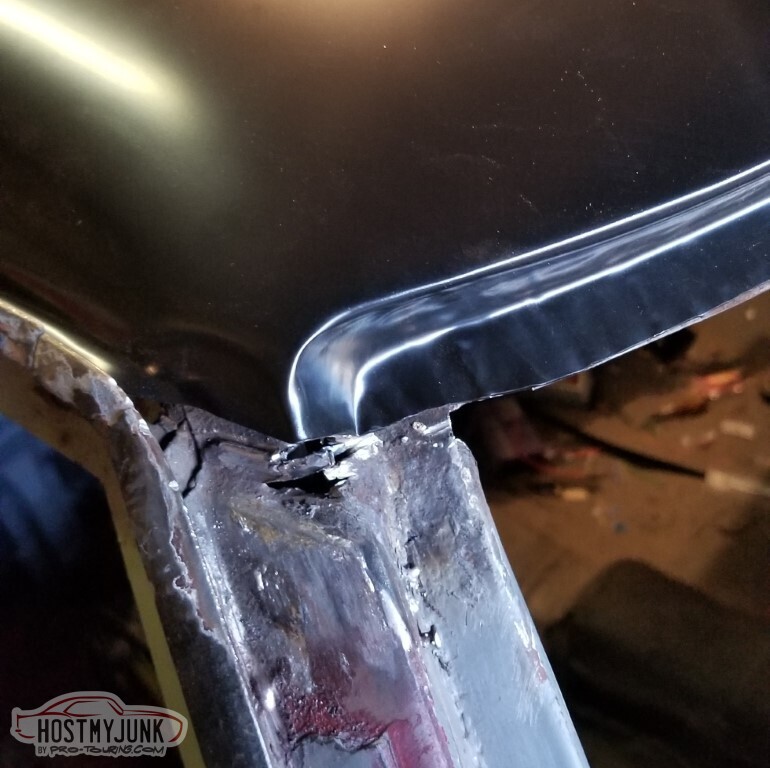
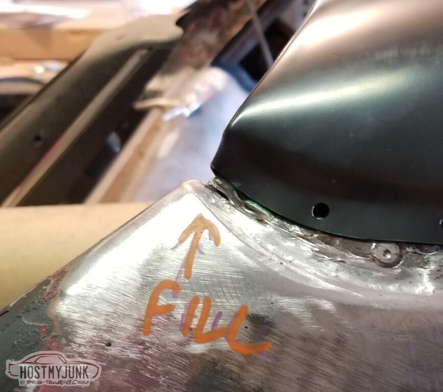
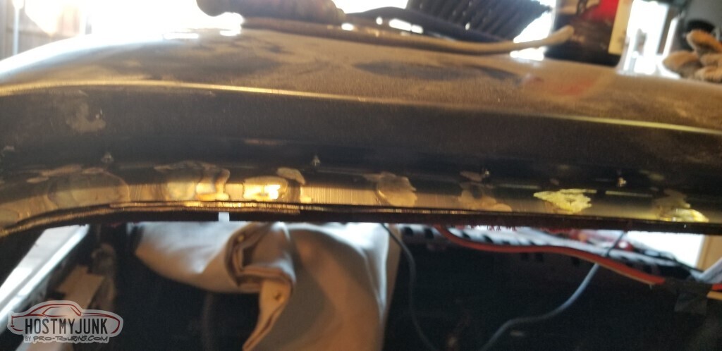
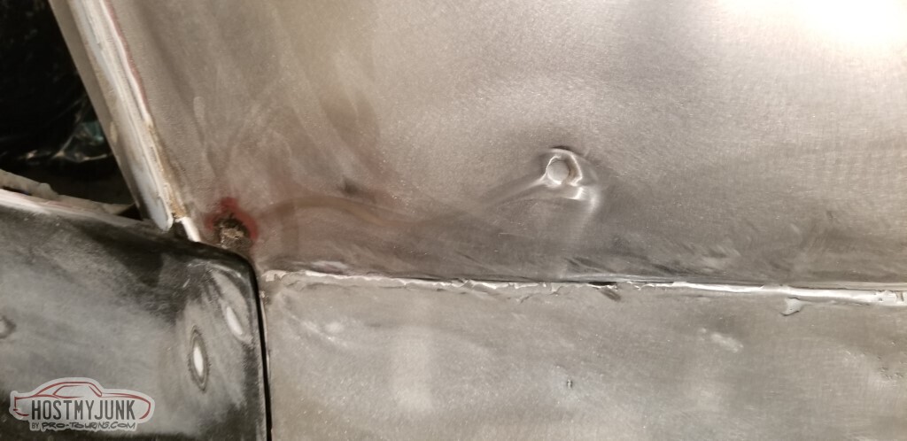
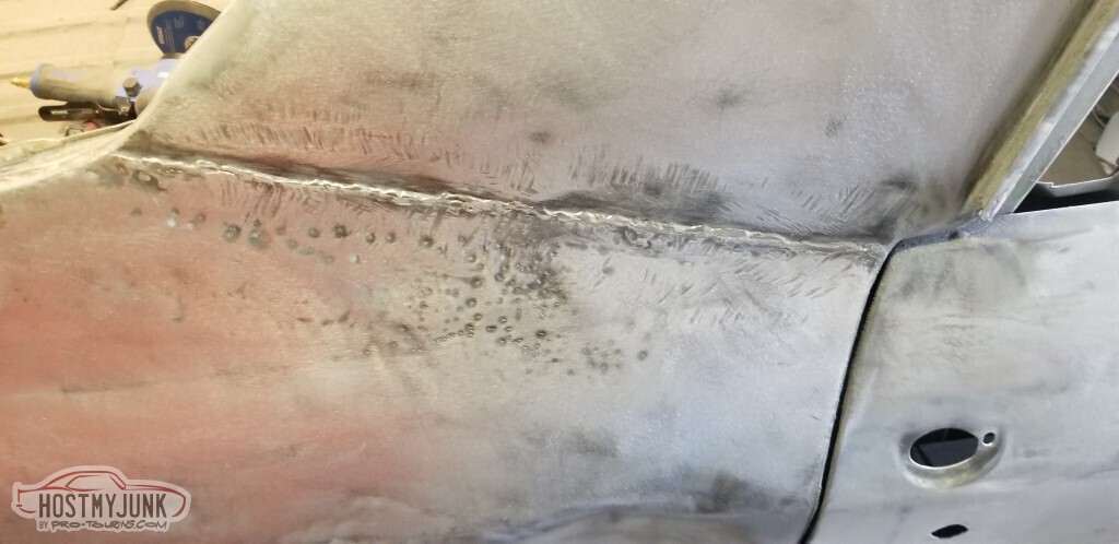
With the roof mounted, the first step would be to put some all-metal on the A and B pillar joins:
Blorp. Needed to go down the A-pillar some to line up with where the lead used to be.
B-pillar more straightforward. (and, of course, once it's there, you need to sand it smooth)
The goal with doing the filler was to get into a position where the seam-sealer could be applied in the drip rails.
Masking is important. I didn't mask all that well. While I have the seam sealer out, let's get this panel mounted *and sealed*.
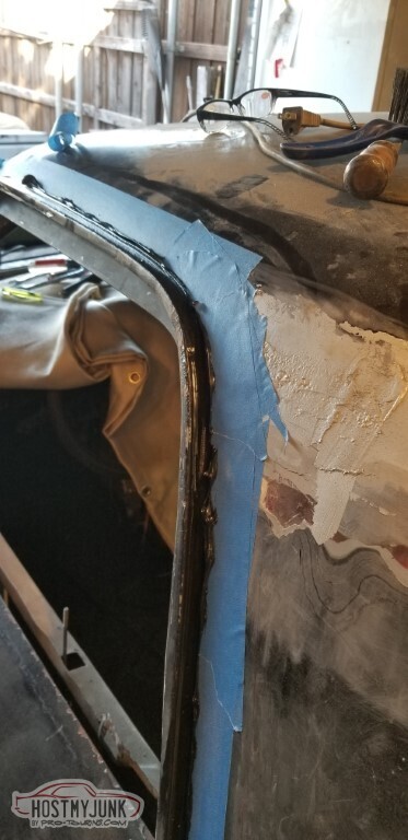
I used the wrong screws, because I ran out of the pan-head philips screws. These will suffice for now.
Also while the seam-sealer was available, I put a little dab on the threads of the trim studs for the windshield and rear window.
All of this was with a goal of getting ready to put the rear window in - which really would require that I have the headliner in place first - to force the ordering the headliner. Not quite ready at this point to put said headliner in though:
I'm not going to want to be grinding so close to the glass, and this needs fixed.
So, it got fixed.
All-metal was handy, too. These got filled with some epoxy putty, and then the whole shelf was covered with more all-metal. Going to try and marry the back edge of the shelf with the window frame. You'll see the covered shelf in other pictures.
And then, She Who Must Be Obeyed had an epiphany about the headliner. She may even be right. She announced that there is no point in worrying about glass or interior until the body is painted. So - let's get started on bodywork!
I figure I'll strip the entire body, then do a cycle of welding in new metal everywhere that needs it, then filler, epoxy primer, high-build primer, epoxy again, then paint. It's maybe not the right time to do this - since we're moving into the "too cold to paint" days (this was from Nov 2021) - but I anticipate a lot of welding.
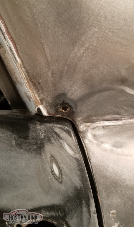
Sanding further down from where the B-pillar joins. I don't know what the round thing is - maybe a bullethole?
Detail.
Appears that the quarters were re-skinned at some point. I don't much like this seam - looks like they only welded part of it and it's definitely not flush.
Also there is random rust-hole.
Carrying the paint-stripping on back, the rear of the lower flange just in front of the wheelwell appears to be made out of bondo. Not all that surprising.
Detail of the lower flange.
Small rust-holes, also not surprising
Rear quarter, naked.
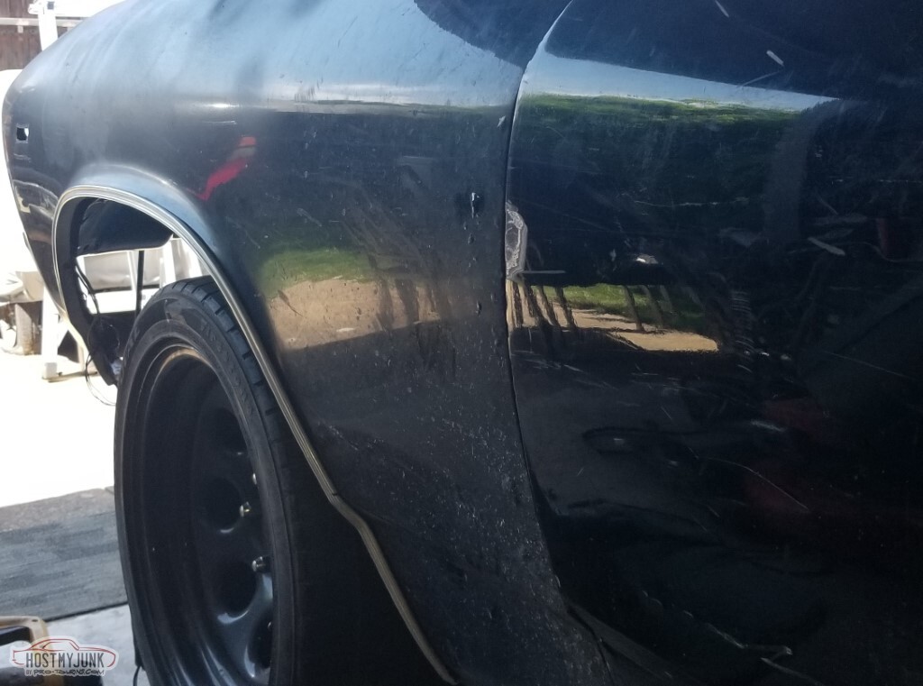
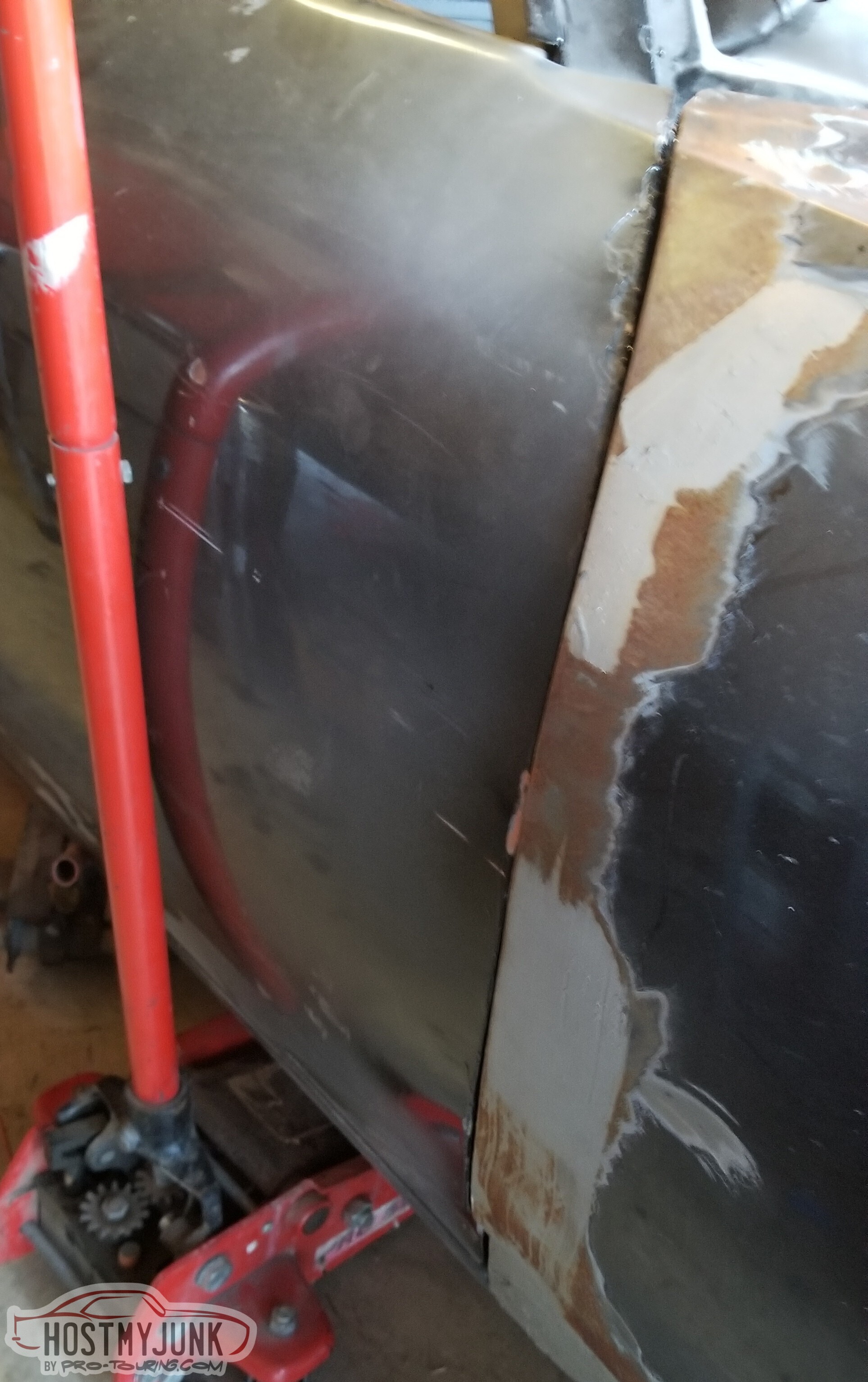
I am pleased to note that there were no real surprises here. It's a pretty straight, relatively low-rust panel.
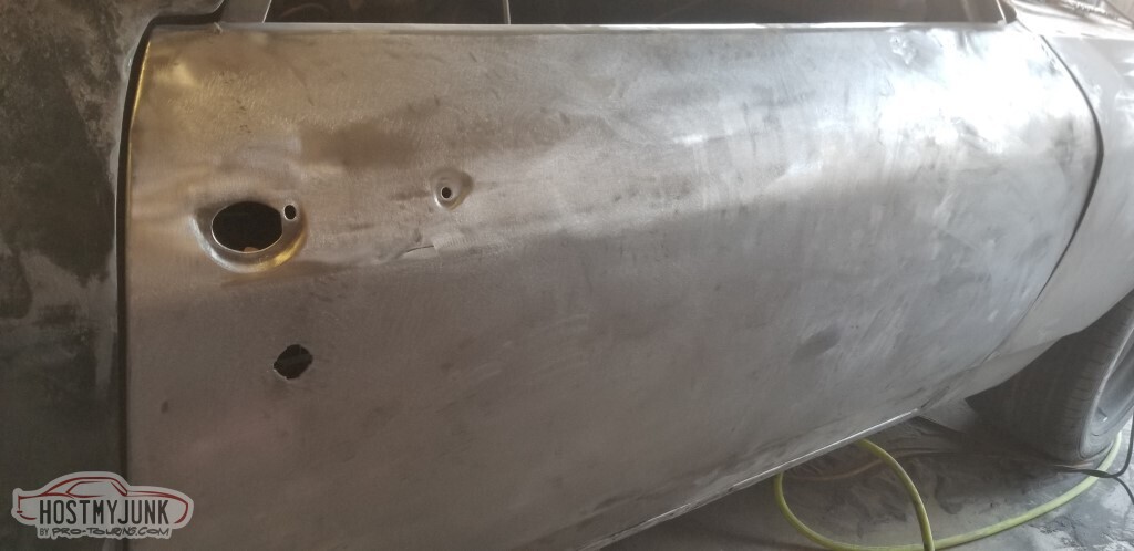
Back edge of the door, however, is another story. Front edge is even worse. A smarter man would probably just re-skin the door.
There is a door-ding just ahead of the front of the handle - you've got to really put some effort in to make that big of a ding. Also there's the side-mirror mount that's not really smooth. All must be worked.
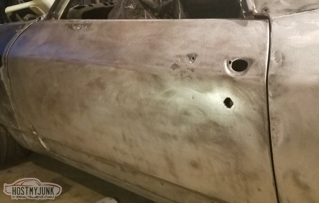
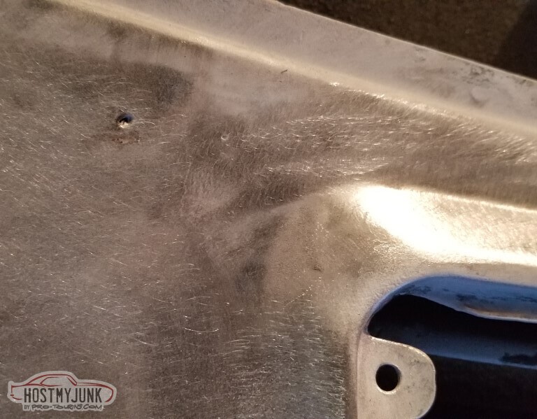
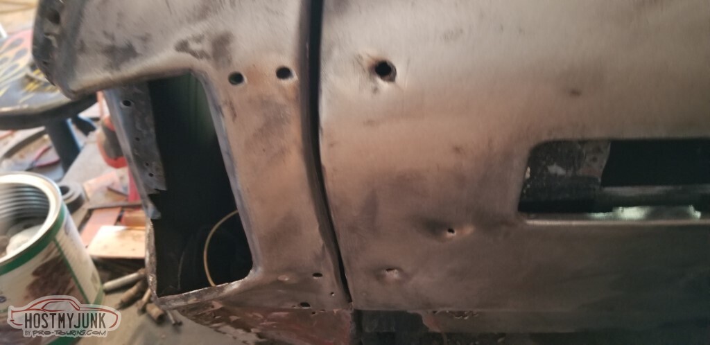
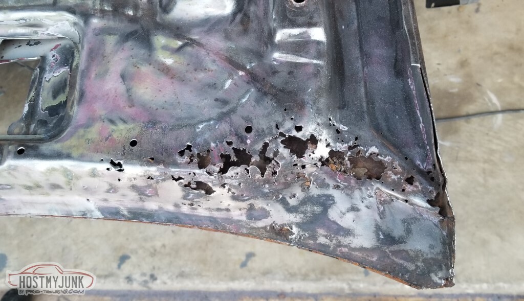
There is a single hole in the top of the fender over the cowl. I don't know why. I blame tinworms.
Some more rust damage on the back edge of the fender.
And it extends further up too.
Driver's side, naked.

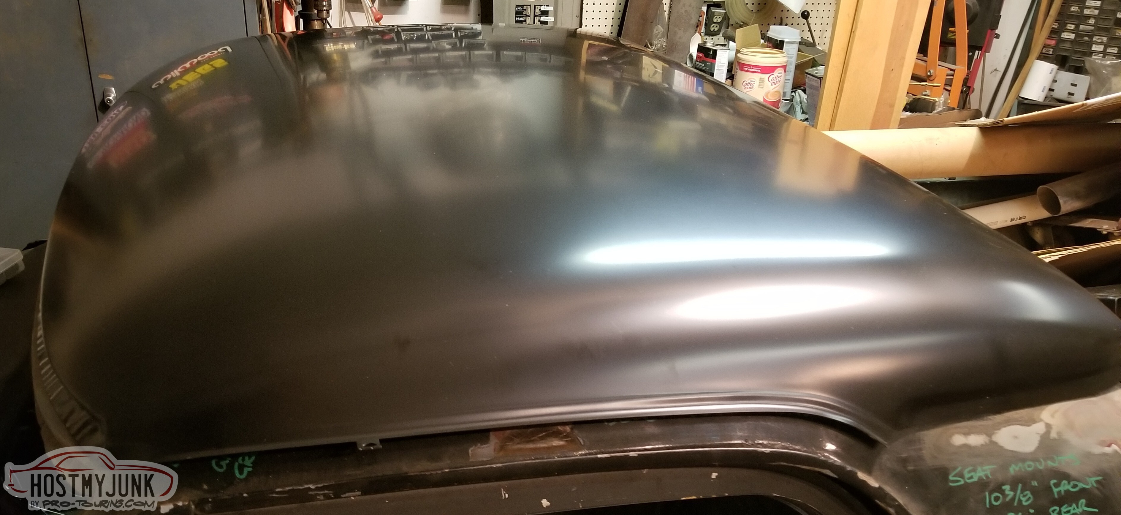
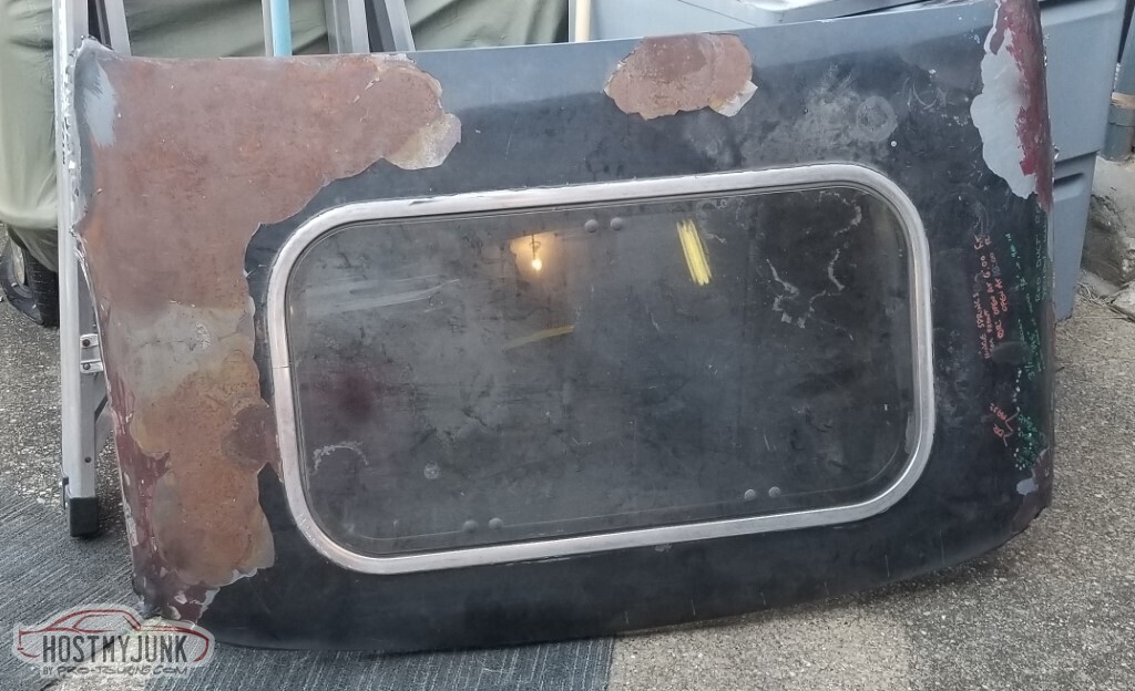
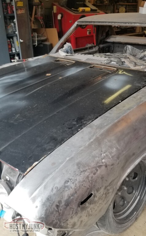
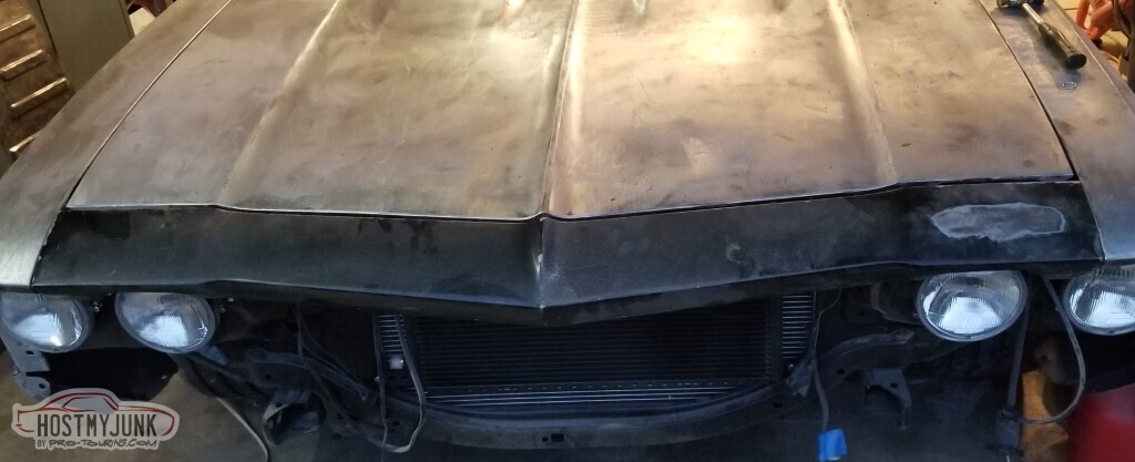
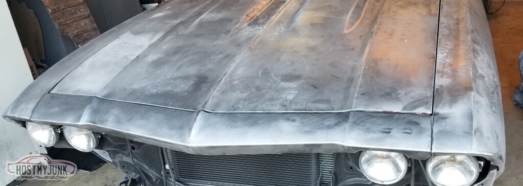
The hood. Sigh. Again with this - smarter man, etc.
In fact, you should probably be reading the smarter man's build instead of mine.
So should I.
Holes.
Rust holes add lightness. Or something.
Went ahead and put the hood "on" for stripping - need to have access and needs to not be outside.
You might notice that the header panel is not installed. That's intentional - I have a choice: I can have access to the attic, or I can roll the car back enough to put this panel on, but I can't do both.
I don't have a good workaround in mind for that.
And as we strip, we find more rust holes.
I can fix this. Or I'll decide to replace it.
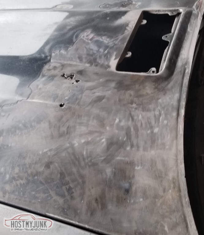
Hood stripped. So-much-dust, it looks like I had the dashboard flocked.
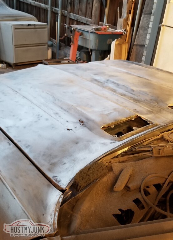
Bonus rust hole - I knew about the lower ones, the upper one was hidden by the paint. Also a tiny hole that will require attention.
I figure the top of the hood will get handled, then I'll flip it over and do the bottom - and prime/paint the bottom before reinstalling.
Also I did this:
3 Days Ago #98
-ɹoʇɐɹǝpoW-
- Join Date
- Jul 2002
- Location
- Mesquite, TX
- Posts
- 4,928
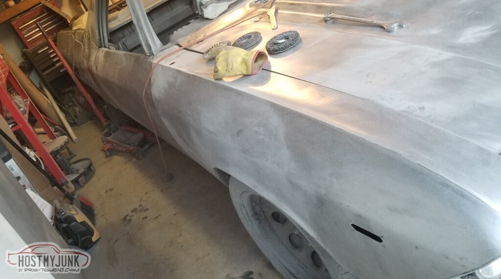
And then the same for the passenger side.
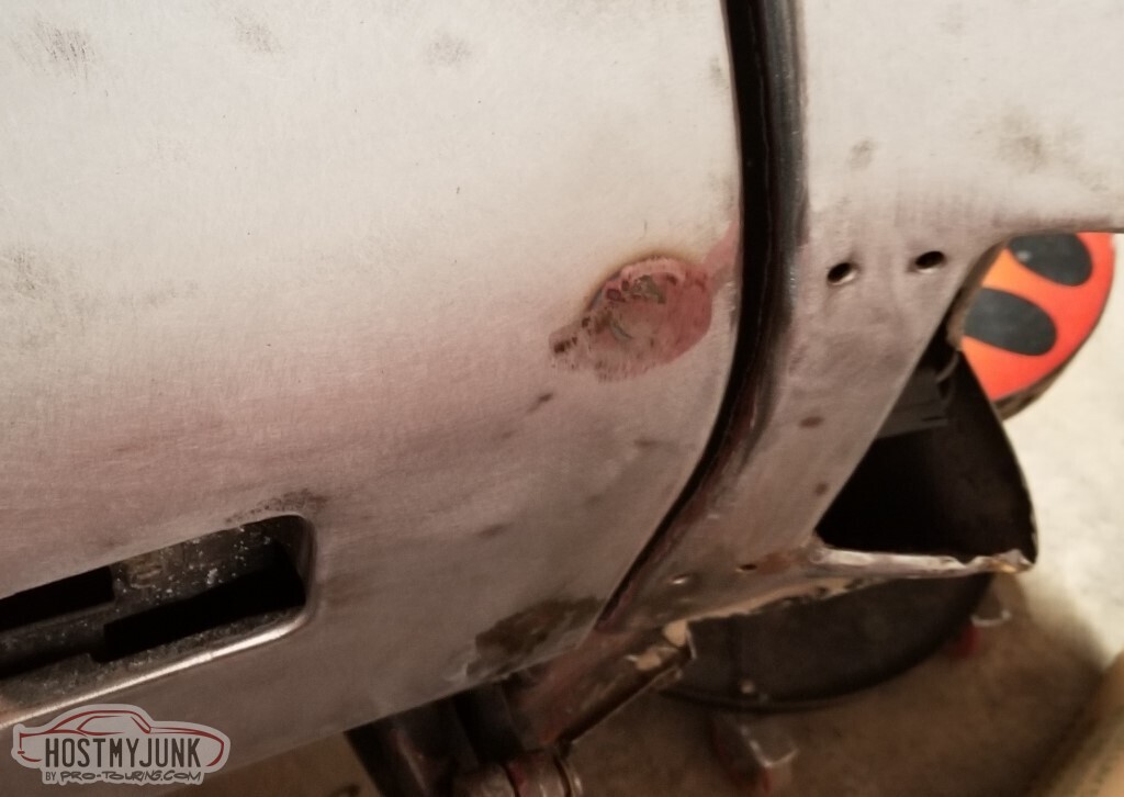
I'd welded up a hole on the top of the fender when I was cleaning up the inside. Never got around to grinding the bead down. Also appears that I missed some rust on the upper edge.
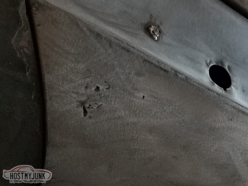
And also missed some on the lower edge.
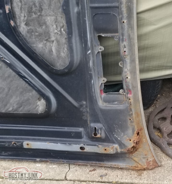
The passenger door was in remarkably good shape.
Except up here where it looks like someone tried to chew on it.
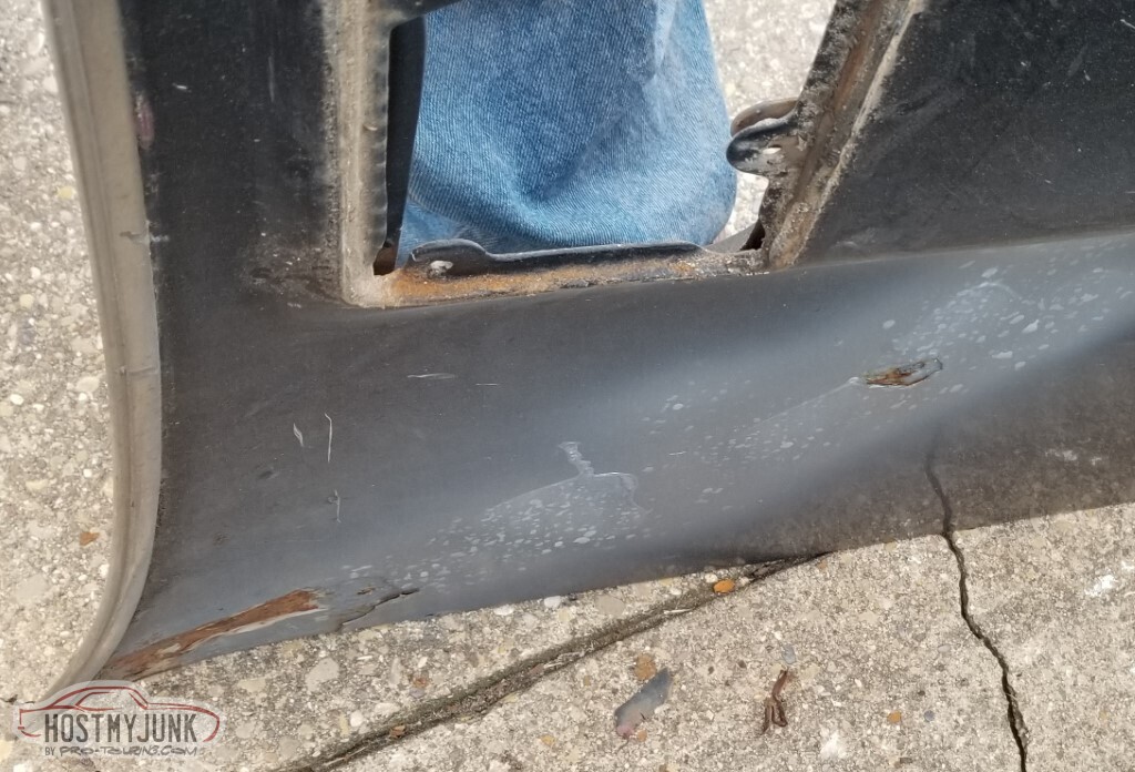
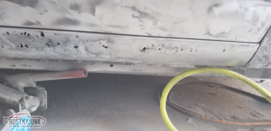
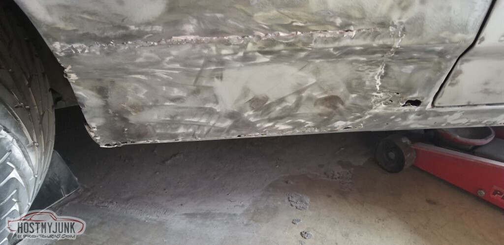
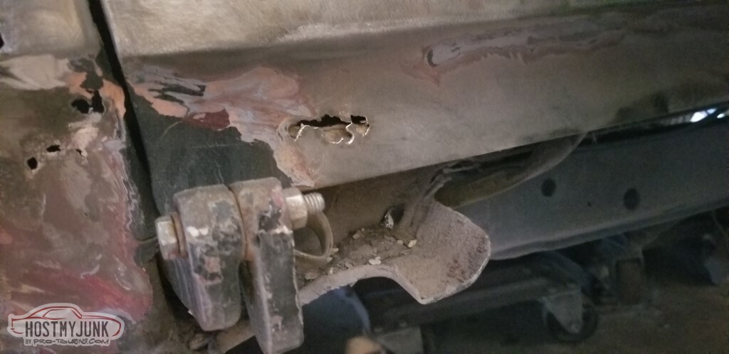
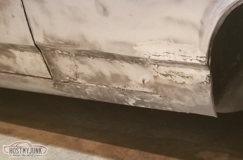
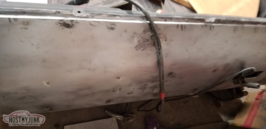
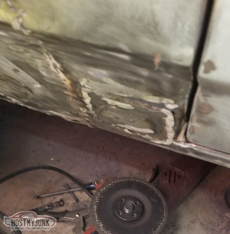
The rocker panel, on the other hand, is well rotten.
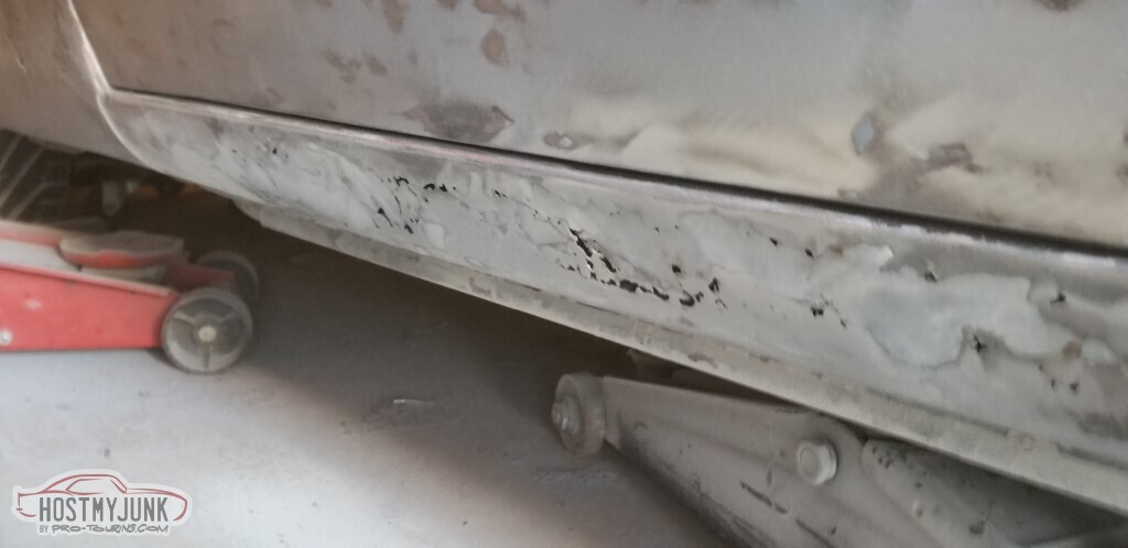
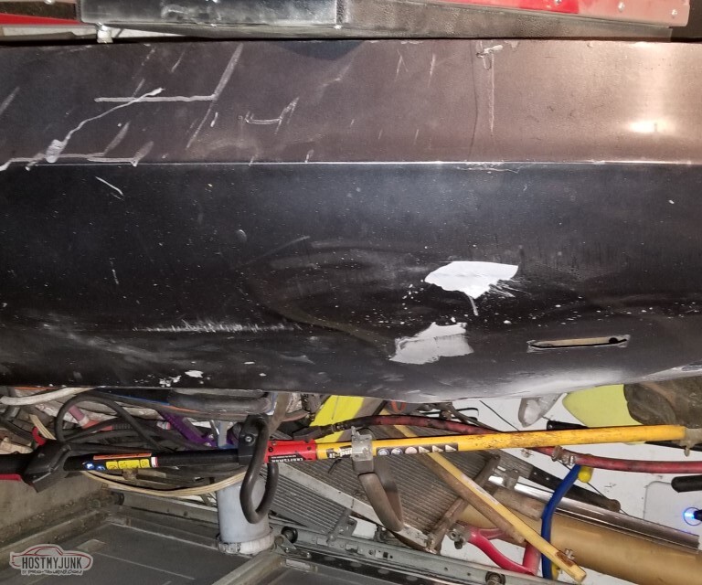
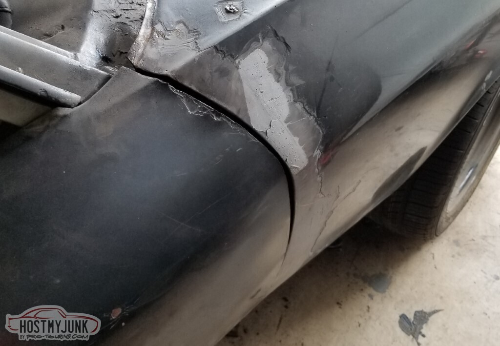
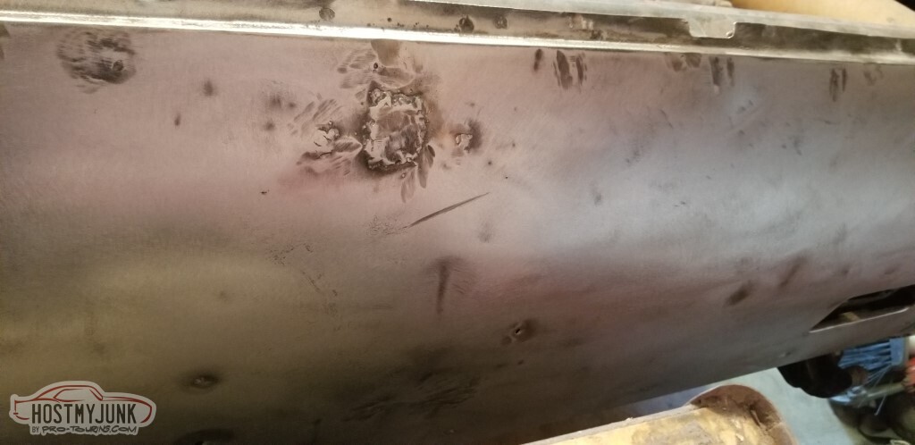
In case you forgot about this dent (see https://www.pro-touring.com/threads/...37#post1358437), it's still a dent.
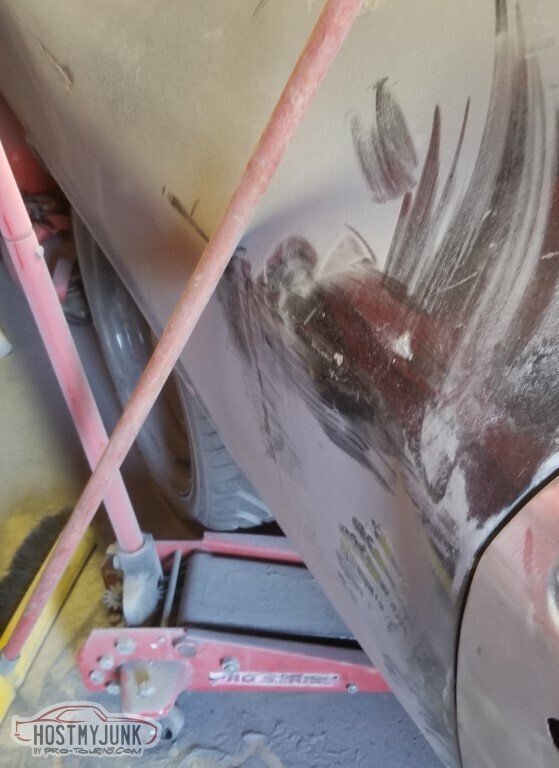
Without paint, it remains dent-shaped.
In progress.
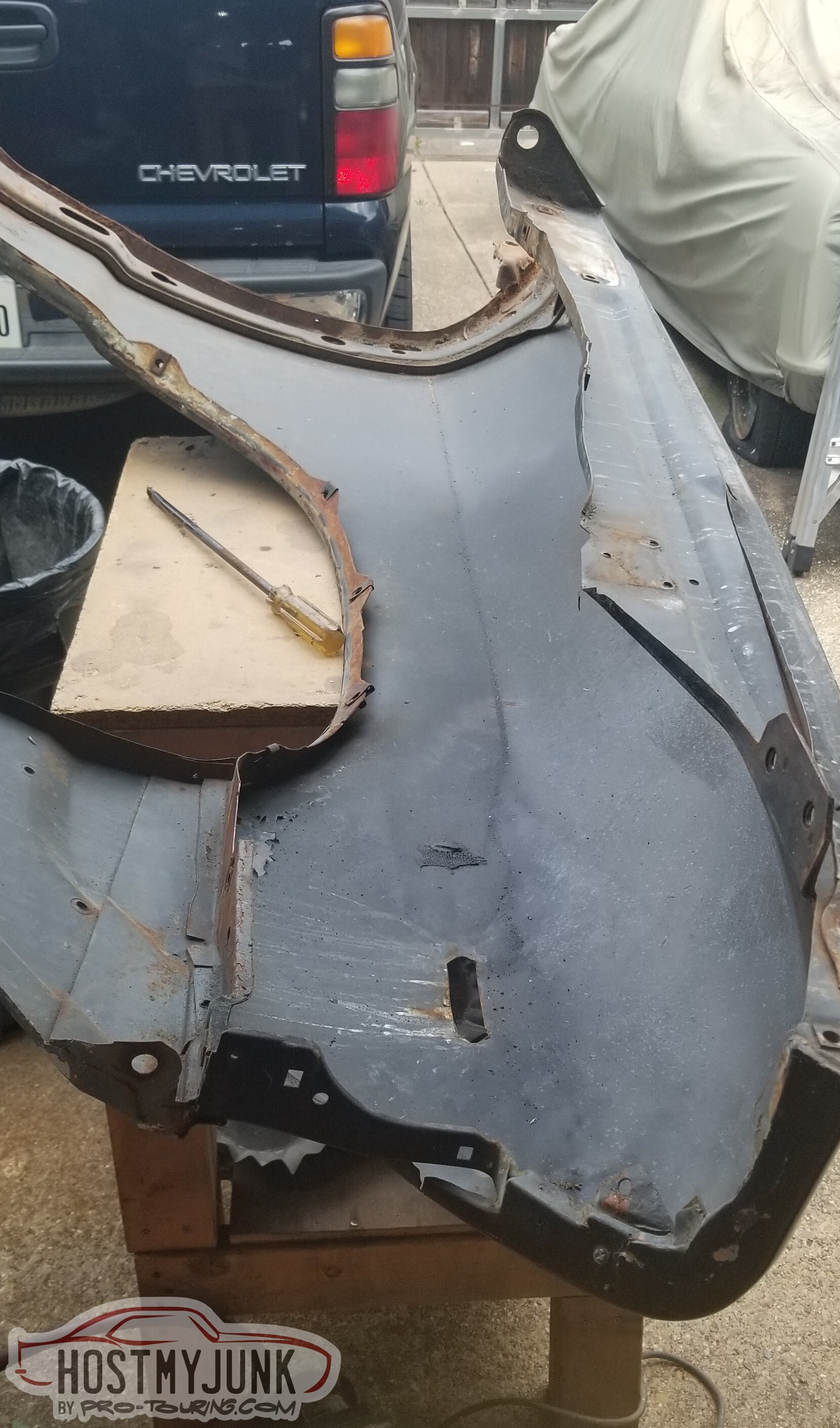
I have a memory of replacing the driver's side fender in front of the wheel, and after welding in the patch realizing that I'd failed to add the bend to the panel. Apparently I mis-remembered, and it was the pass side. The bondo here approached half-inch thick.
I chipped some free with a chisel.
Lots of pick marks around this seam.
Some rust holes around the patch (also need to cut the patch out and put one with the right bend in it)
... also the rear flange on that panel is just wrong.
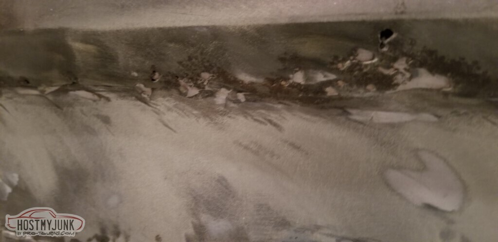
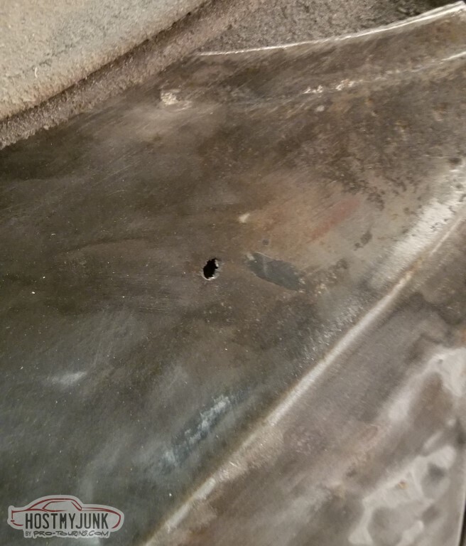
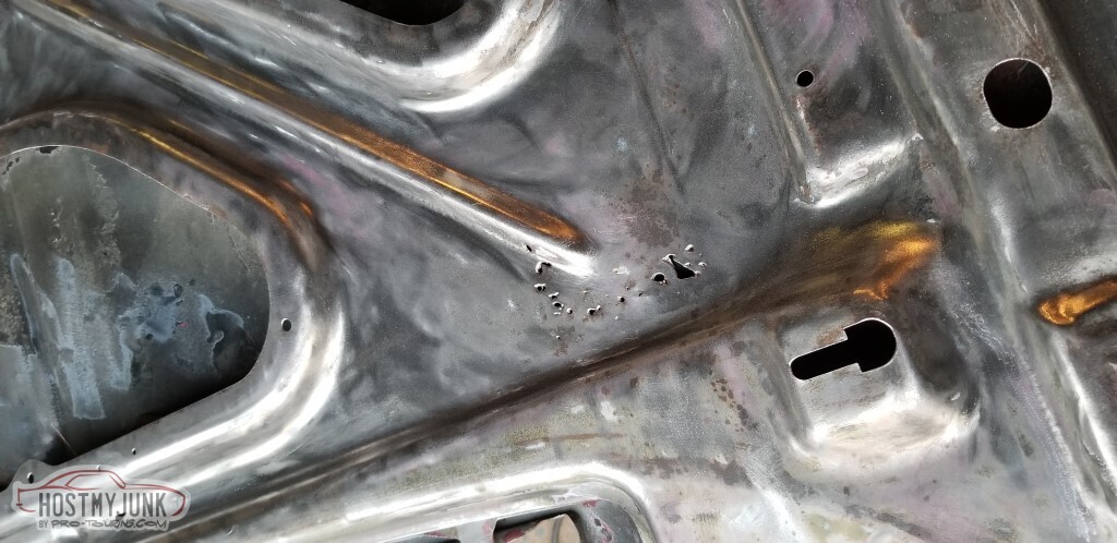
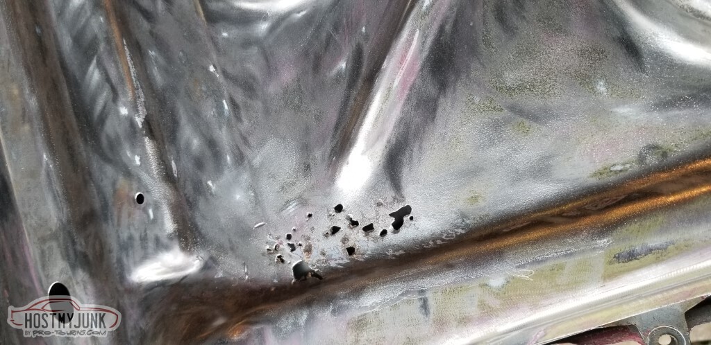
These are not rust holes. They are, however, rust damage. Unsure how I'm going to deal with them.
There is a light at the end of the tunnel. Unfortunately, that light is visible only through rust holes.
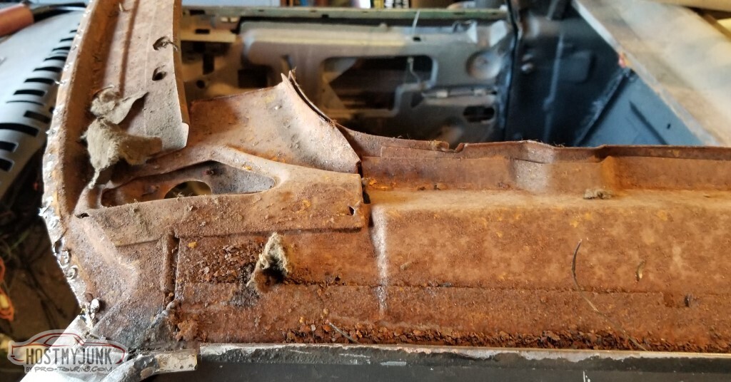
There's also some rust at the trailing edge of the pass rear - this would be covered by the bumper.
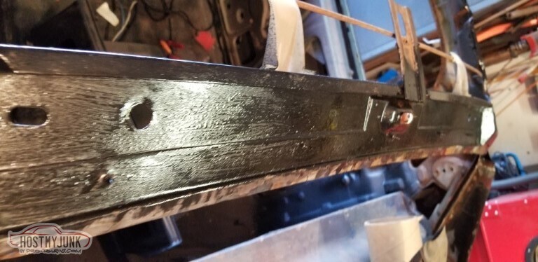
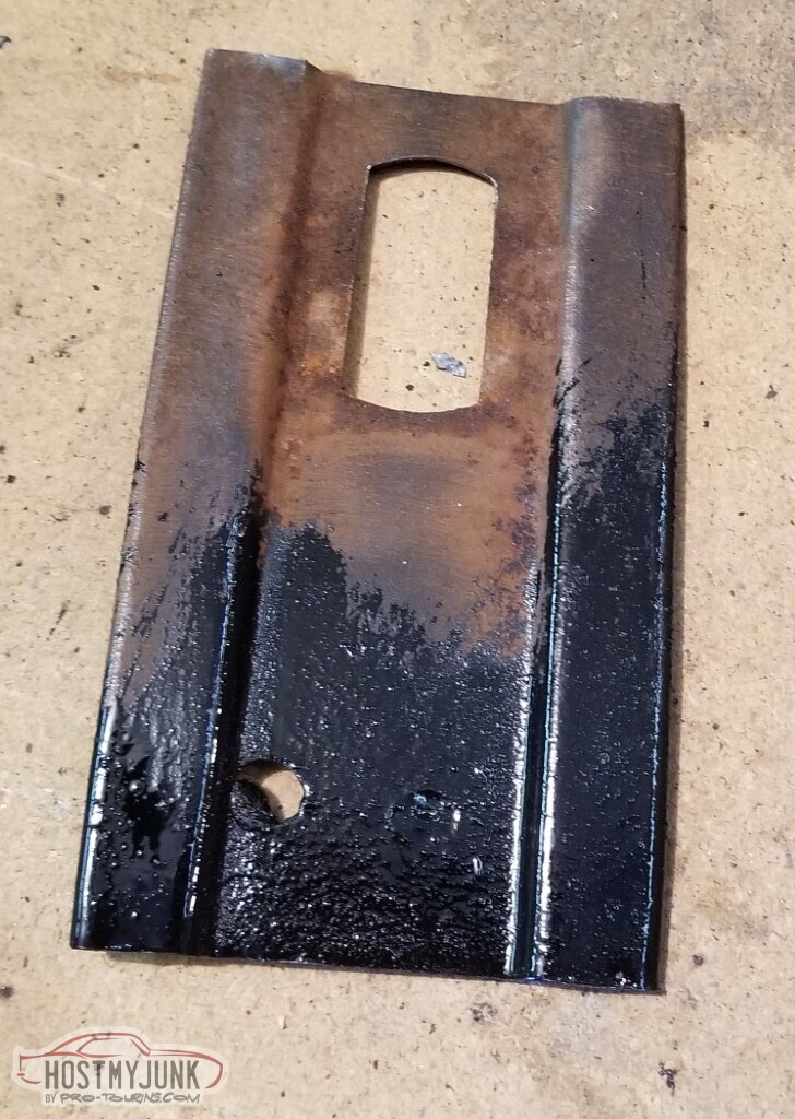
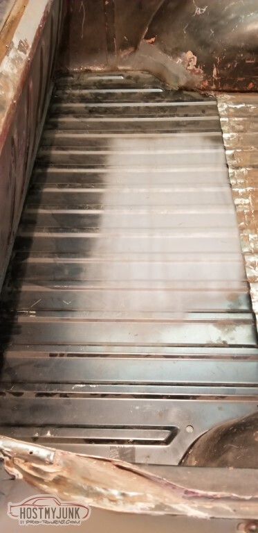
The tailgate closeout panel has definitely seen better days. Will be trying to straighten this some.
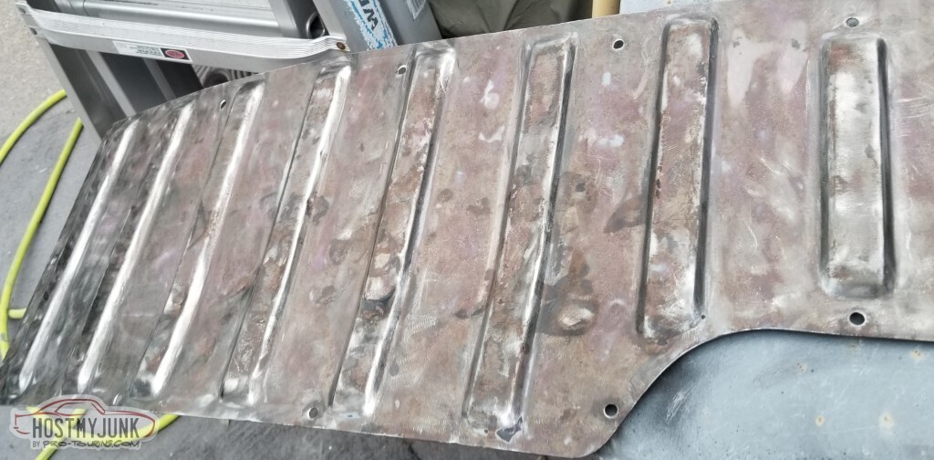
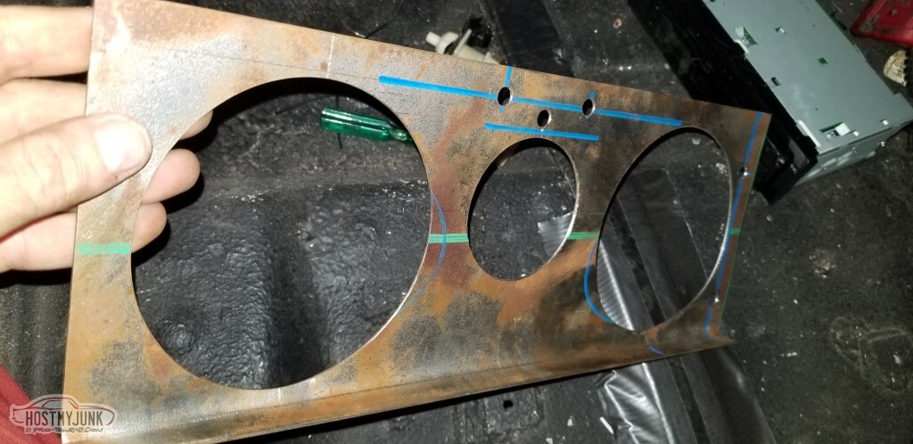
The General definitely didn't skimp on mounting holes for trim. These need welded up.
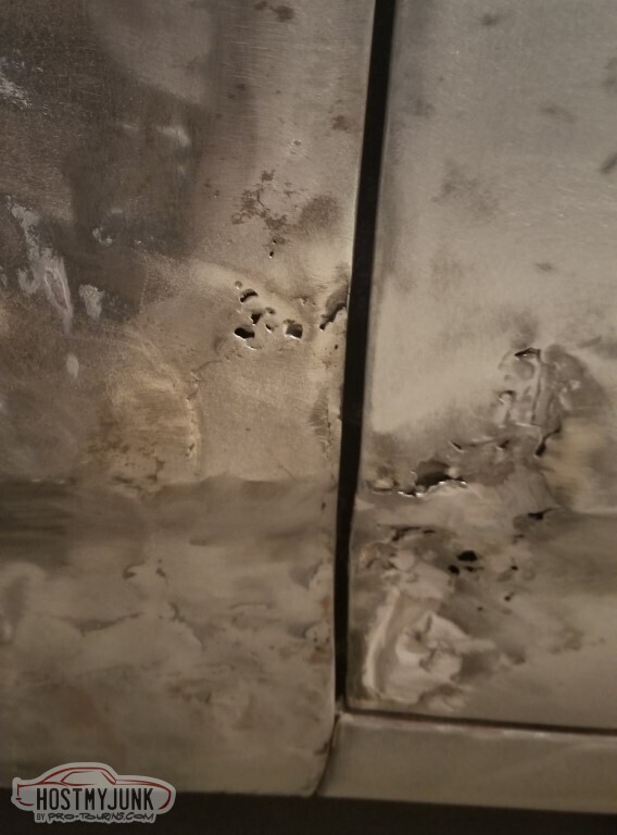
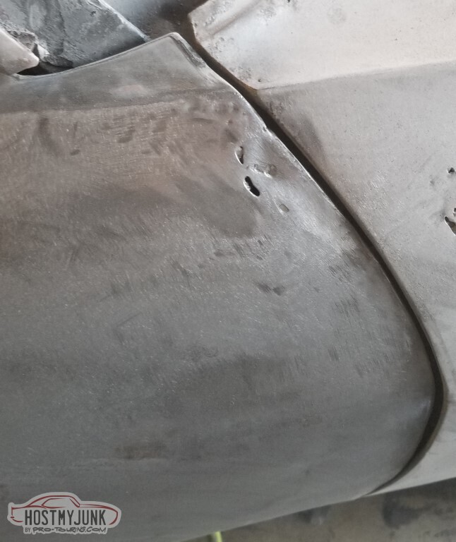
Lots of issues going on here.
Start with the tailgate handle - it's dented in and poorly welded, also all the dark spots are low spots that need straightened.
https://j.hmjimg.com/2024/04/19/2111250021.jpg
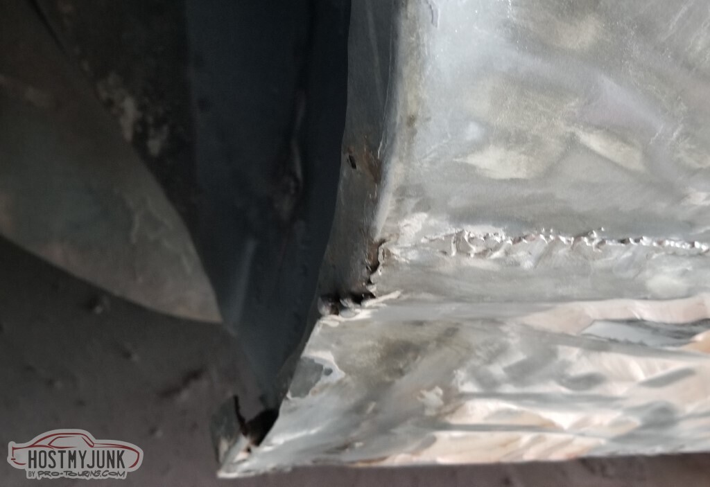
There is rust right above the hinge, on both sides.
I can't really get the wire brush attachment in here.
Near as I can tell, the "correct" plan is:
- Rust repair
- Pull dents
- Filler
- Epoxy prime
- High-build primer
- Sand
- Epoxy primer (as sealer)
- Base and clear
so that's what I'm going to do.
3 Days Ago #99
-ɹoʇɐɹǝpoW-
- Join Date
- Jul 2002
- Location
- Mesquite, TX
- Posts
- 4,928
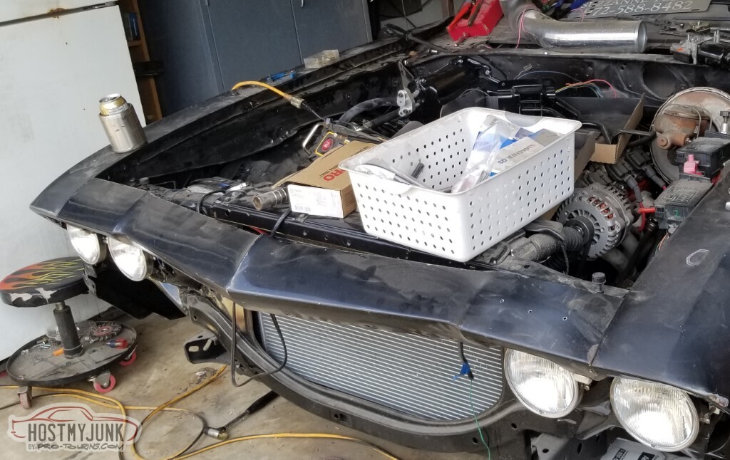
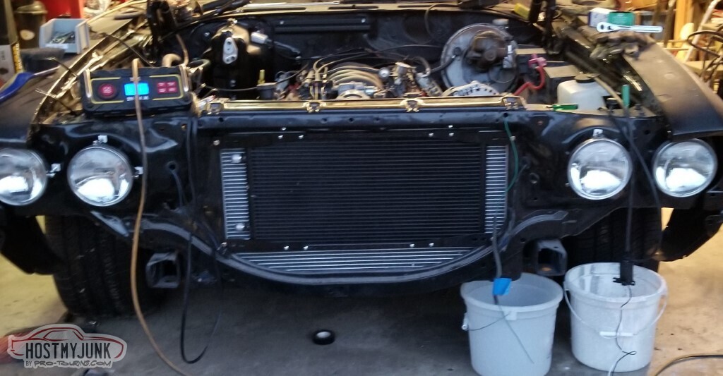
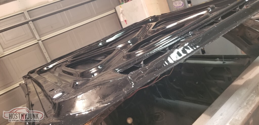
Time to work on the header panel. Wanted to get it mounted before stripping it.
This is made slightly more complex in that the garageg door opener has failed and the car is just long enough that I can't squeeze by to unlock the garage door with this panel mounted.
Not pictured: A day spent installing a new garage door opener so I don't have to squeeze past.
Stripped the header panel. This is officially the panel in the best shape on the car.
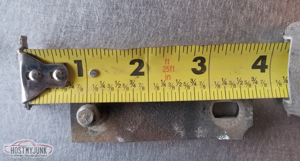
I found the wiper motor arm! Now I know for sure that the ball is 2 1/4" from the motor.
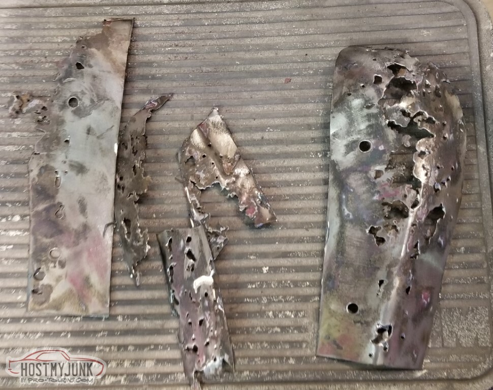
Started cutting out rust on the hood.
I guess I skipped the whole "taking pictures" thing for that first one as we jump now to first welded and ground, and second in progress.
Far side (Nos. 3 and 4) welded
Center (no. 5) welded.
Here's what I cut out. No further pics of the top of the hood at this time.
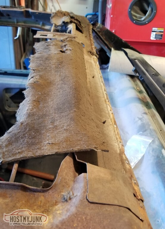
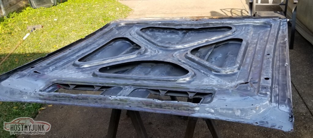
Flipped the hood over, strip the paint from there (not particularly worried about the areas the insulation will cover); the trailing edge is much, much worse than I expected.
And it's even worse on this side.
Smarter man wouldn't have got this far on this hood, and certainly would have gone new hood shopping at this point. Let's fix this instead.
The more paint/bondo I take off, the more rust I find.
Some small rust holes further forward
(on both sides)
I cut rust away.
Patch 1 started (white spray paint to put something on the metal I won't be able to get to once this is done)
Just a reminder: I'm still a horrible welder.
Second half of patch 1, plus the cowl-seal holes have been drilled.
First part of patch 2. Or 3, if you coulnt the little tab.
Patch 1 (mostly) ground
Bring on the all-metal!
On both sides!
Did the same for those small holes further forward. It's not perfect, but it's the underside of the hood, it doesn't have to be.
It's winter.
According to the weather forecast, today is the only day for the next few weeks that it'll be warm enough to put paint on the underside of this hood. It's not a particularly good day for it - wind 15-20 with gusts up to 30, 20% chance of rain... but it is the day we've got. Let's make the best of it.</p>
Sawhorses in the driveway give the best chance for debris to blow onto the hood.
Start with Summit branded epoxy primer, because that's what I have. It's black.
Didn't really go on so well; bad surface prep is partially to blame. Move on to the black paint I got from Sherwin-Williams back in https://www.pro-touring.com/threads/136673-derekf-s-69-El-Camino-build?p=1396885#post1396885.<a href="http://www.derekf.com/images/2112100026.jpg"><img src="http://www.derekf.com/images/2112100026_tn.jpg"></a>
More clouds gather.

First coat of high-gloss clear (also from that same SW run)
If it hadn't been the underside of the hood, I probably would have done a real thin coat of filler to handle pits in the metal. It's the underside, this is really what the metal looks like
The edges are really the important spots - in the previous incarnation, the black paint flaked off a lot on the edges, revealing previous colors. Since I took it all down to bare metal, there are no previous colors now.
Move the hood into the garage before the rain actually starts!
Next week when more hands are available, I'll get this hood mounted and adjusted. The top is still in bare metal, it'll get paint with the rest of the car.
3 Days Ago #100
-ɹoʇɐɹǝpoW-
- Join Date
- Jul 2002
- Location
- Mesquite, TX
- Posts
- 4,928
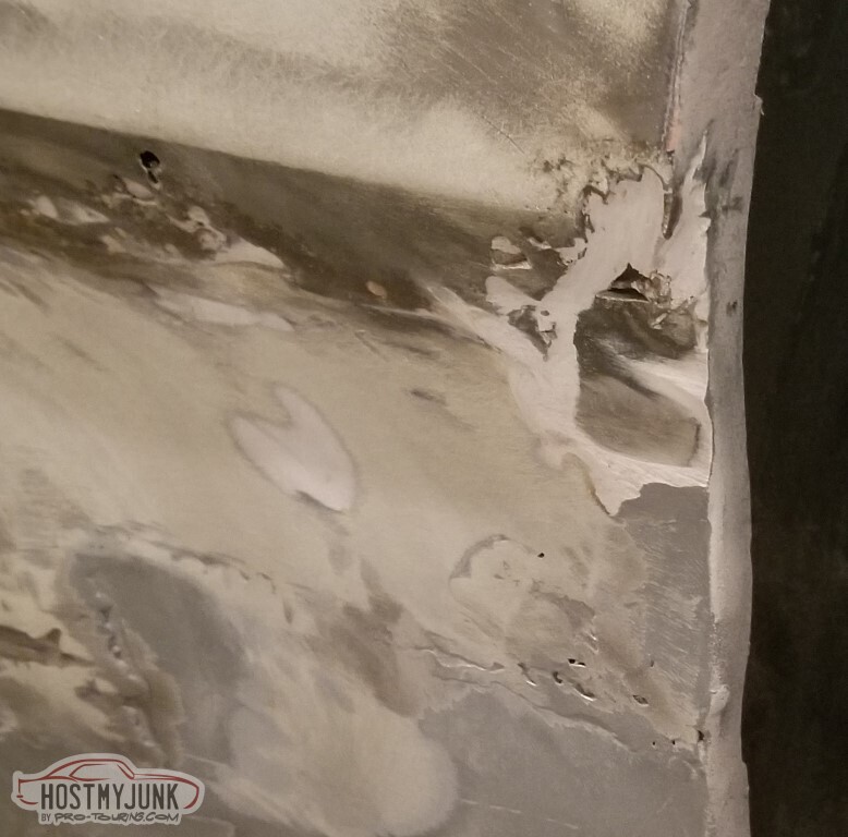
In accordance with the "Perfect Paint Job" documentation on the SPI site (hyperlink may break, can search on the term), I want to get the all-metal on the weld joints and then put epoxy primer on everything. Plenty of rust to work on.
Started on the front of the driver's door. Did put some paint on the semi-rotted framework here.

Here's what I cut away.
Patch mostly welded.
Patch welded and ground. Looks pretty good.
Next up, back of the door.
The damage was mainly filler.
Welded. The sharpie lines are to tell me where the bends should be - this has a slight arc to it.
Ground.
Closed up the holes at the side mirror mount
Fixed the small rust hole just behind the driprail and the bullet-hole thing.
Patch just behind the door.
(ground)
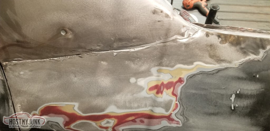
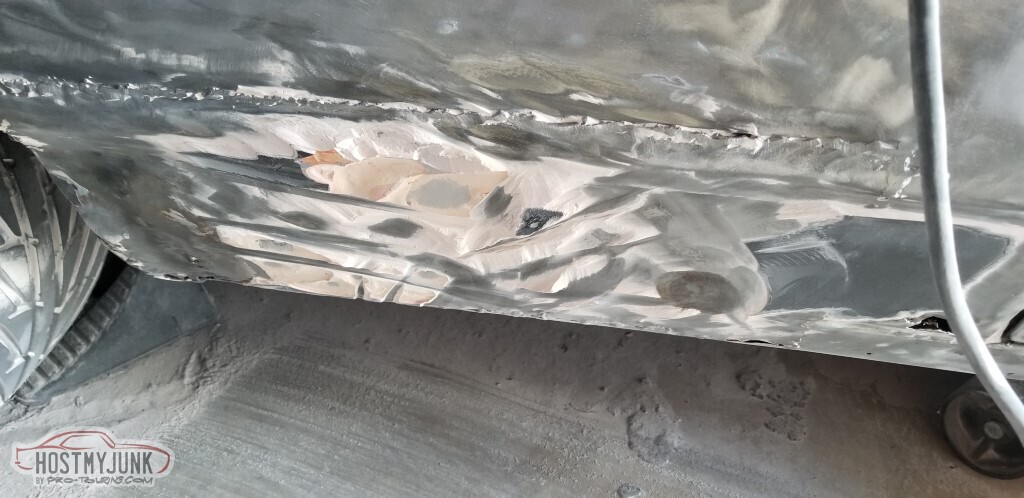
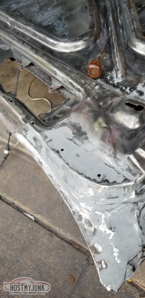
Then the rear part of the lower quarter, just ahead of the wheel. Here's what came out. It, too, was primarily filler.
Welded the patch in. Also had to patch the wheelwell arch.
The weld on this part of the hood had warped a ltitle bit, and there was oil-canning on the panel near the near edge.
Shrinking disk. I don't really know how to use this device.
But I shrank things. Maybe it's better. I also added some dents, which probably made things worse, but it's not oil-canning anymore.
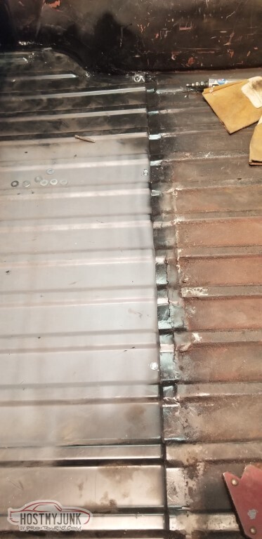
Moved on to the rear panel and tailgate. Welded up the trim holes here. Ground them, too, but didn't photograph it.
Along with the tailgate.
More tailgate, and then the (not pictured) pass side trim holes.
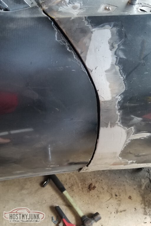
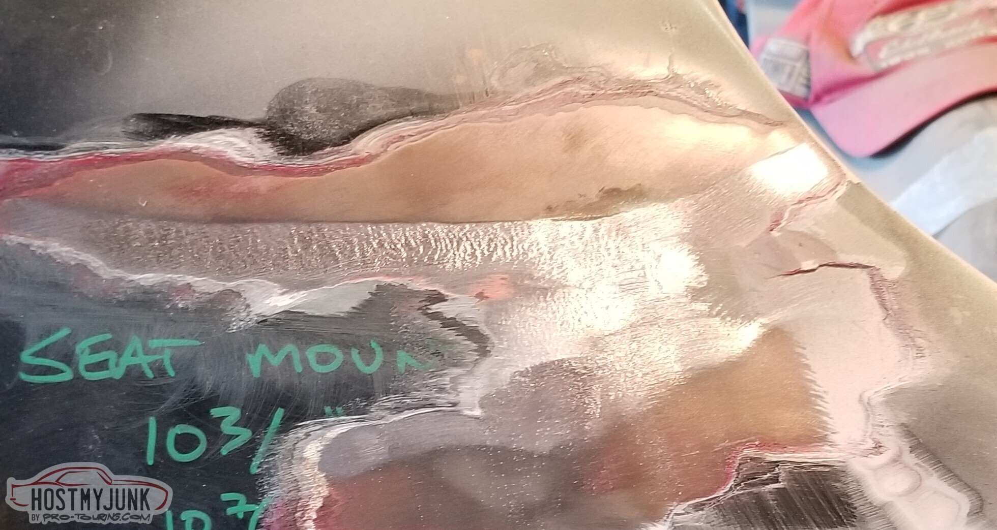
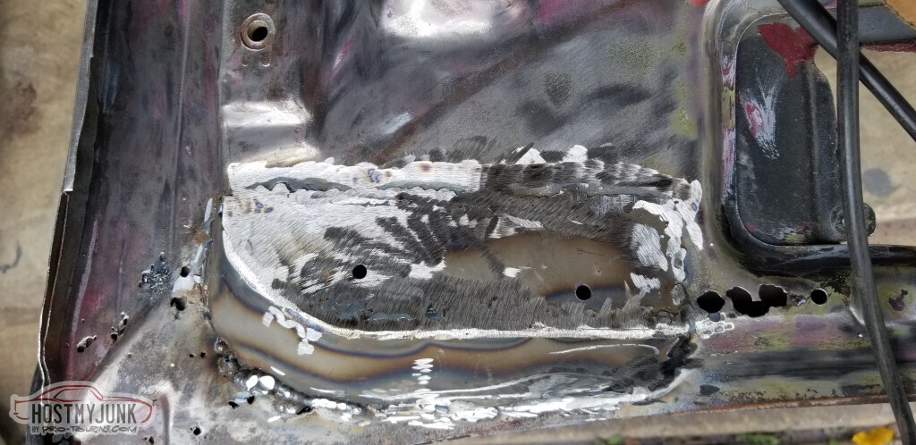
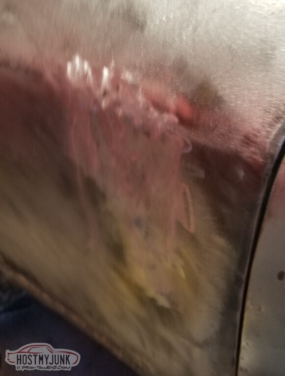
Moved along to the big dent on the pass side.
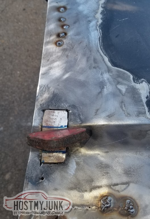
I've had that stud welder since early 2013, don't think I knew just how well it worked.
The stud welder also works well for patch panels, I can attach one of the little copper studs to the face of the patch and hold it in place while I start welding.
Also - the lower edge of this panel, as also noted previously, was welded in as a flat panel rather than bowed; I used the stud welder to add some curvature there (not pictured).
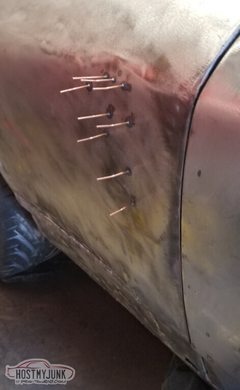
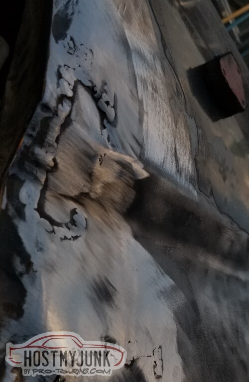
It looks smoother than it is... but it's definitely not a big dent anymore. No oilcanning, neither. Still needs some work, and maybe I'll get to try the shrinking disk again. Important part is, of course, that it not be proud of the normal surface, and I'm not quite sure at this point.
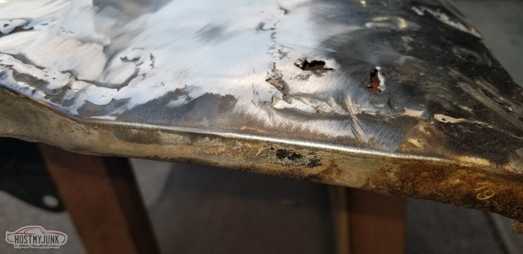
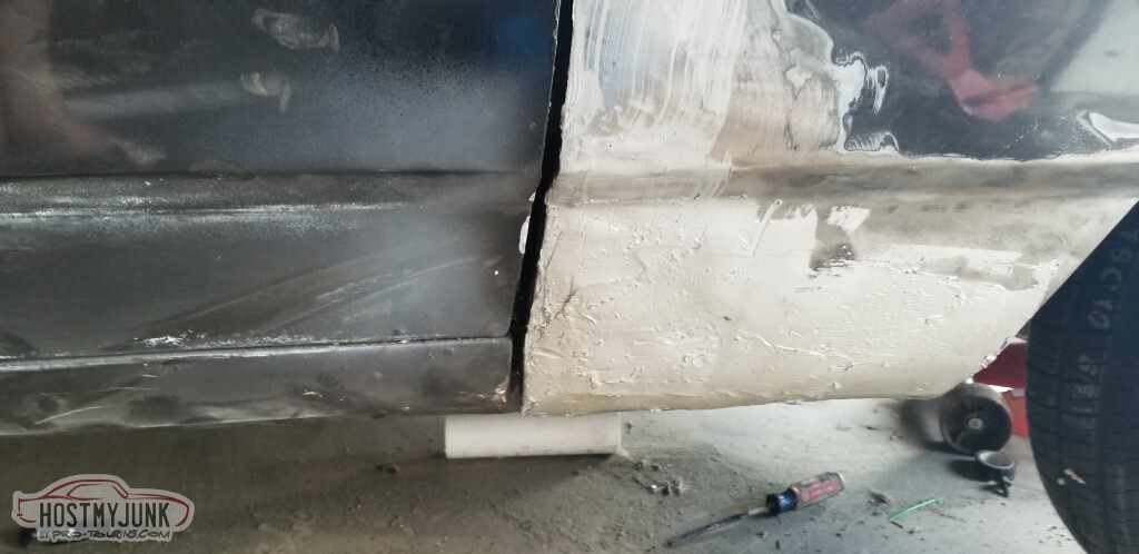
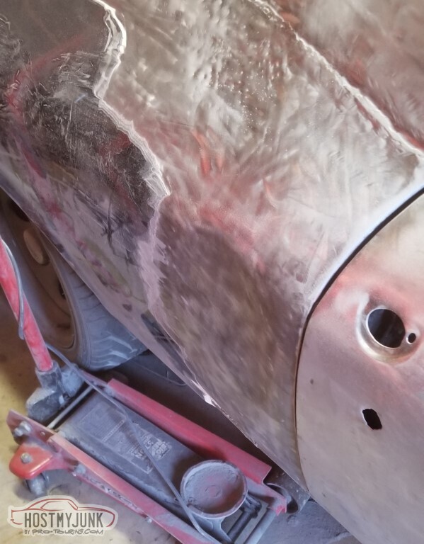
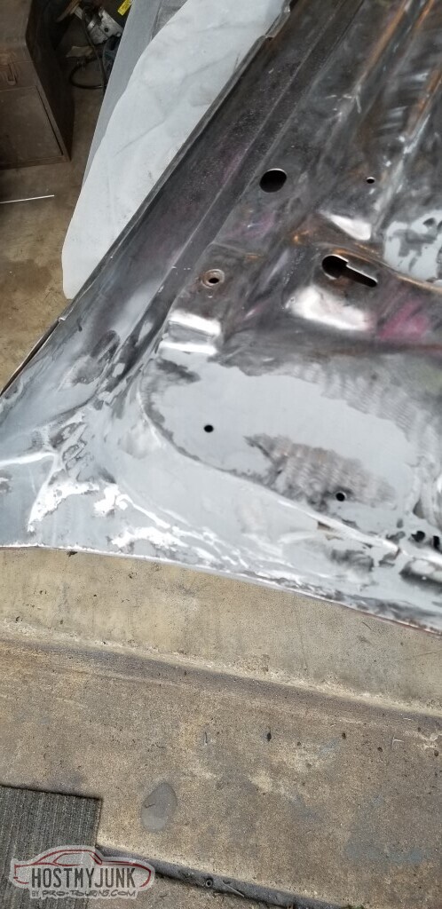
The rust further down needed cut away and replaced, of course.
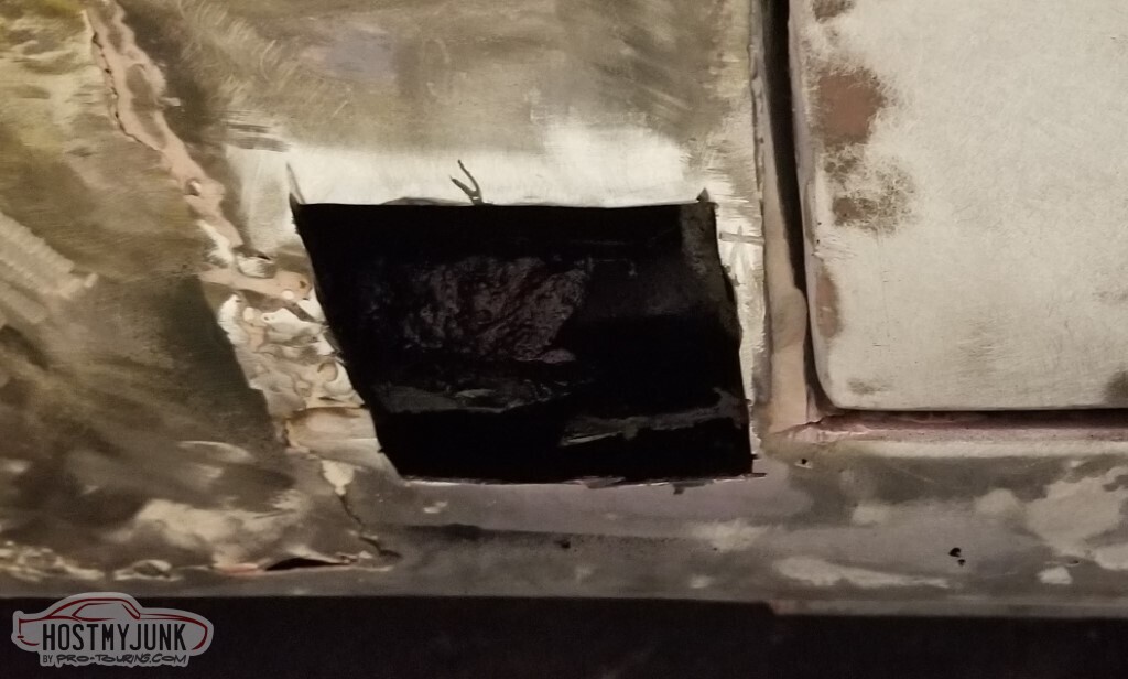
Grinding not complete. The rust in the rocker panel is so bad that I've made a pilgrimage to the local Summit to get a patch panel for it. All they had in stock was the rocker for a Chevelle - but should work Just Fine.
New can of all-metal too. Forecast has it warm enough for primer pretty much for the rest of the year (!) so will try to get this all knocked out over the next few days.

 Reply With Quote


