

Results 21 to 40 of 89
Thread: derekf's 69 El Camino build
-
05-15-2021 #21

 -ɹoʇɐɹǝpoW-
- Join Date
- Jul 2002
- Location
- Mesquite, TX
- Posts
- 4,901

Current plan is to take care of the front suspension -- I bought a set of AFX spindles out of the tax return, but of course the car wasn't ready for them as of the last update. Still isn't, but it's a lot closer.
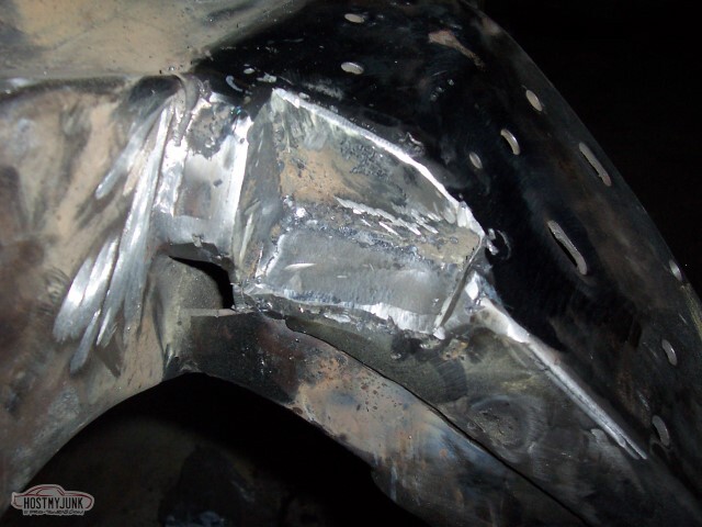
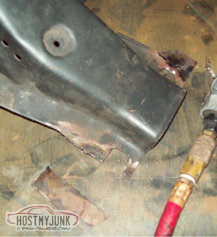
If you recall, the engine needed to be removed to create the notch for the AC lines. I started by cutting out the metal for the notch, and then cleaned all the grime and paint and rust off the frame.
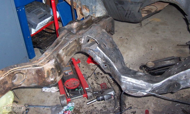
Of course, once you take something to bare metal, you really should prime it so it doesn't rust.
The primer I used was the Tractor Supply enamel primer. I really, really, really wish that when we were househunting we'd found a house where the heater pilot wasn't in the attic above the garage, and the water heater pilot wasn't in a closet off the garage -- this would have been much easier had I been willing to spray.
I do not know if I should have used a hardener in the primer, but it's too late to fret on that now. Obviously, I didn't use any.
With the primer getting closer, it was time to fill the notch. Started with some 1/8" thick bar stock of the correct width.
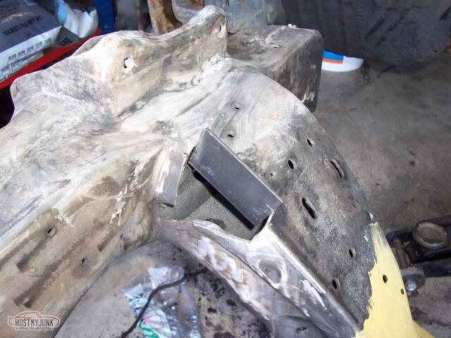
(Alternate view)
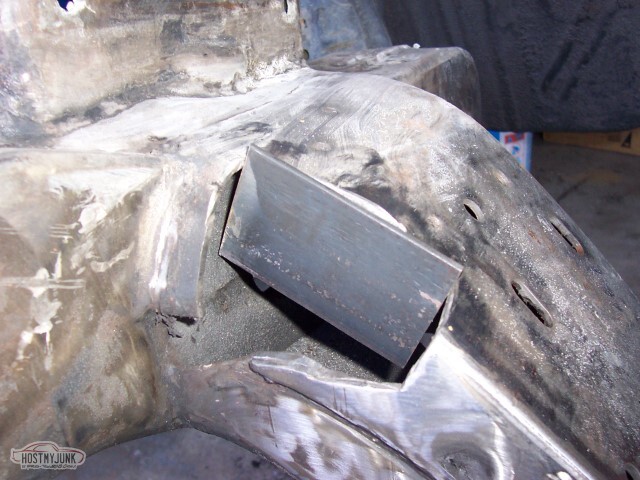
Not that involved to cut the sides as well. Learned several neat things here. The first was that it's better to worry about frame work before you convert your MIG over to use .023 wire; the second was that I shouldn't be trying to weld at all when I'm having feed problems (the little nylon screw that holds the spool on kept tightening down and not allowing the wire to feed). That is my excuse for these ugly welds.
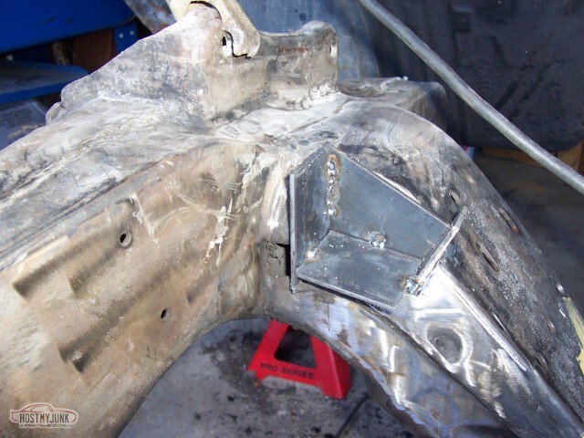
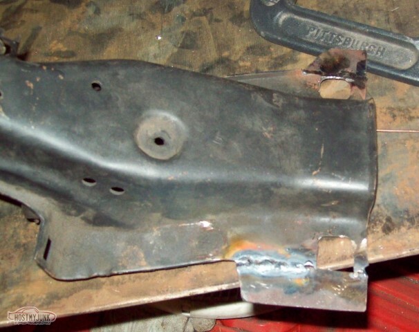
Still having feed problems. You'd think I would have stopped and tried to figure out what was going on earlier. The wiring going to the TIG does not really support me running at the amperage level I'd need for this -- but then I realized, the TIG also does stick welding... so that's what I did. Here, you see that the outer edges of the notch are filled in (in some areas).
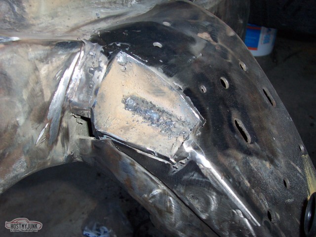
And then I tried to clean up the ugly crap weld in the inside.
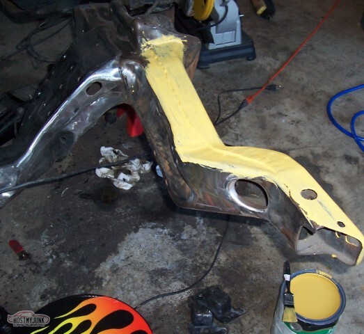
And then I applied primer.
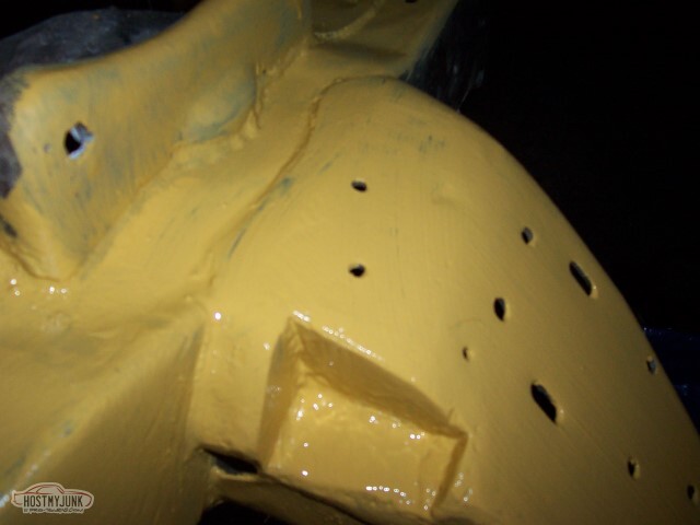
And then I applied more primer.
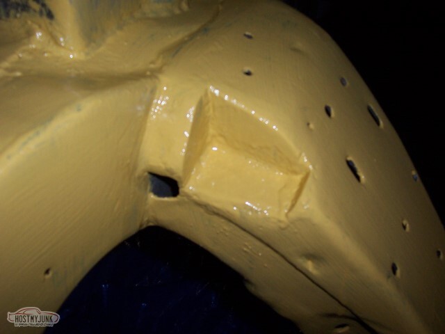
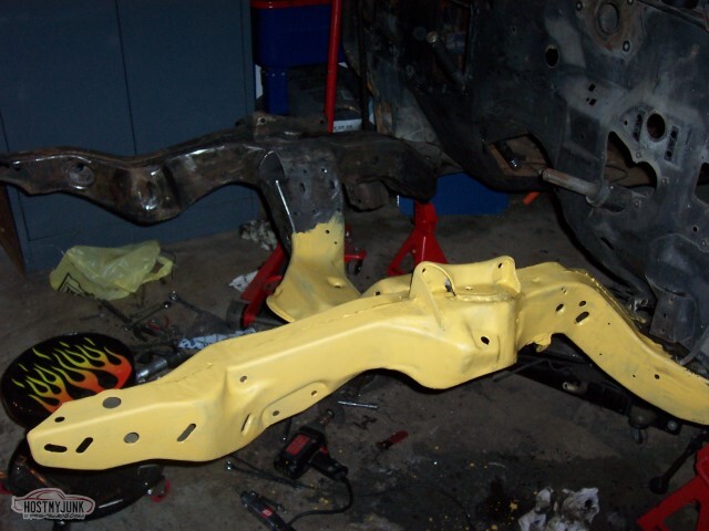
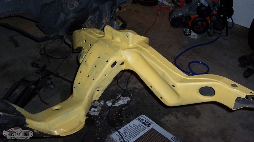
Eventually, the whole thing was in primer.
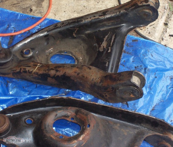
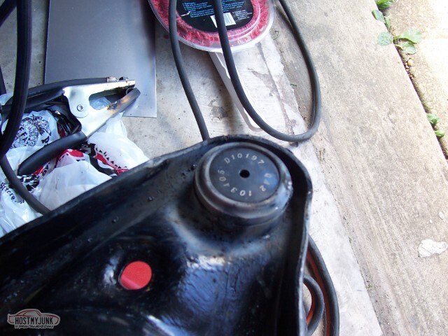
Next up - the lower control arms. These had seen better days - the POR-15 I'd applied when I reworked these back in '99 or so really didn't stick all that well. Wasn't too worried about the cost of replacing the ball joints and bushings -- the previous ones I'd bought were from Autozone with their lifetime warranty.. so after quite a while of digging, I found my receipts for the ball joints (one from 2000, one from way back in 1991). I didn't need them; Autozone's records go that far back. I took all the front end components I had receipts for up there - all the tie rod ends, the lower ball joints, the tie rod sleeves, and the bushings. They only had one bushing and the two lower ball joints to replace mine with - they gave a cash refund on the bushings, and I kept the tie rod ends and threw them in the parts washer.
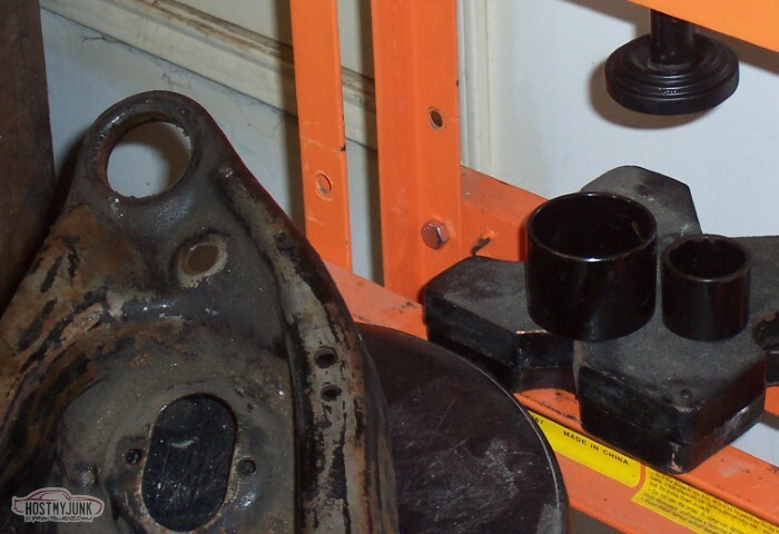
I'd picked up a ball joint service set from Harbor Freight a while back. It worked decently, but the clamp-thing wasn't big enough. Luckily, I have a press (although I used the vise as much as I used the press)
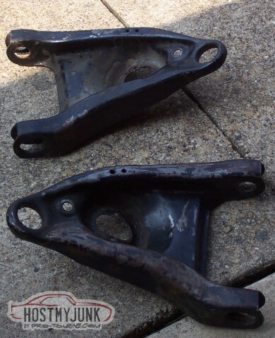
And with the LCAs cleaned off, they too got thrown in the parts washer.
Then, off to the sandblaster.
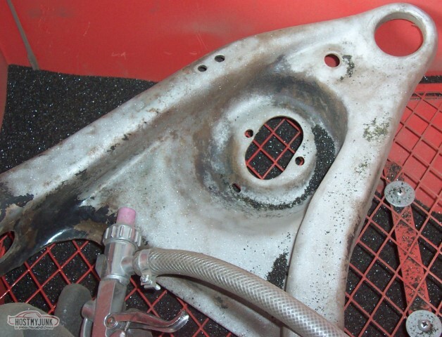
They cleaned up pretty good. Could have sworn that I took pictures of them after I put them in primer, but I can't find them now.
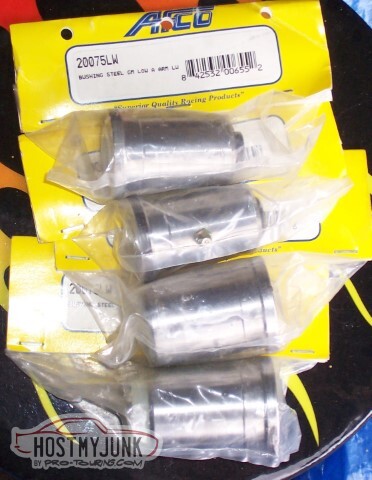
Steel racing bushings! But wait - a problem: my LCAs have an oval bushing, not the larger round one. Luckily, I have a local circle-track store (it's a huge store) - Smiley's Racing. Walked in there, someone asked 'Can I help you?', I told them what I needed, and they told me it'd be on this aisle, in a red bin on the right. They were wrong.. the oval bushings were in a cardboard box to my left, but still, I was able to buy the bushings and go home with them instead of having to pay shipping. I like patronizing local shops like that, hopefully they'll have more stuff I need.
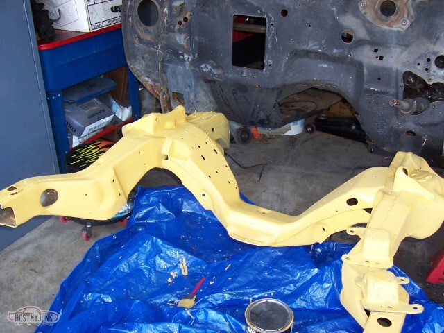
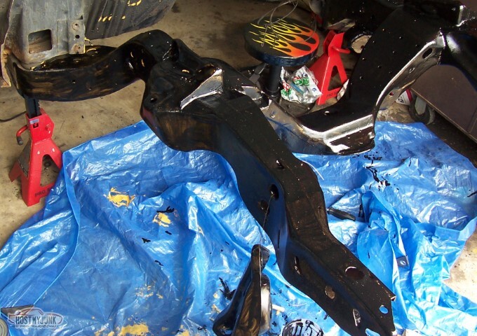
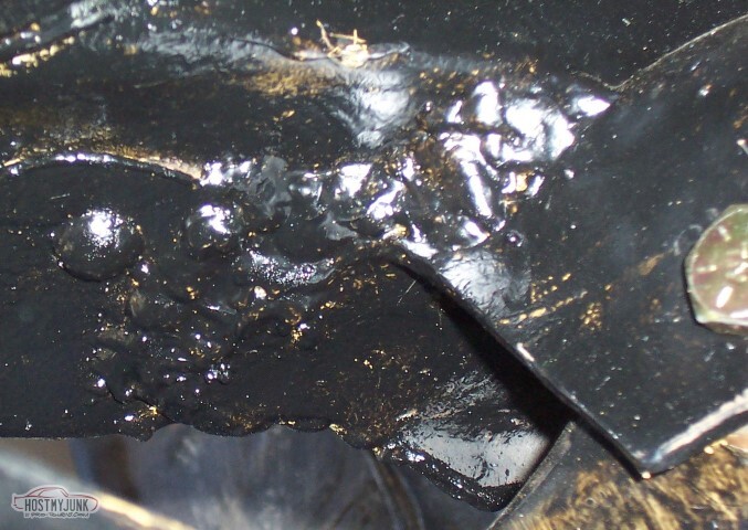
So I've received word that my clutch rebuild is complete and the clutch is on its way back to me. I'll really need to have the frame ready to put the engine back in before the clutch shows up, so today was frame-day. Paint is low-gloss black Valspar implement enamel (also from Tractor Supply) that I did use the hardener in. This is first coat; the beigey-yellow primer shows through in a lot of places..

Another view of first coat, with crappy job on the LCAs.
This is second coat. Coverage is much better here.
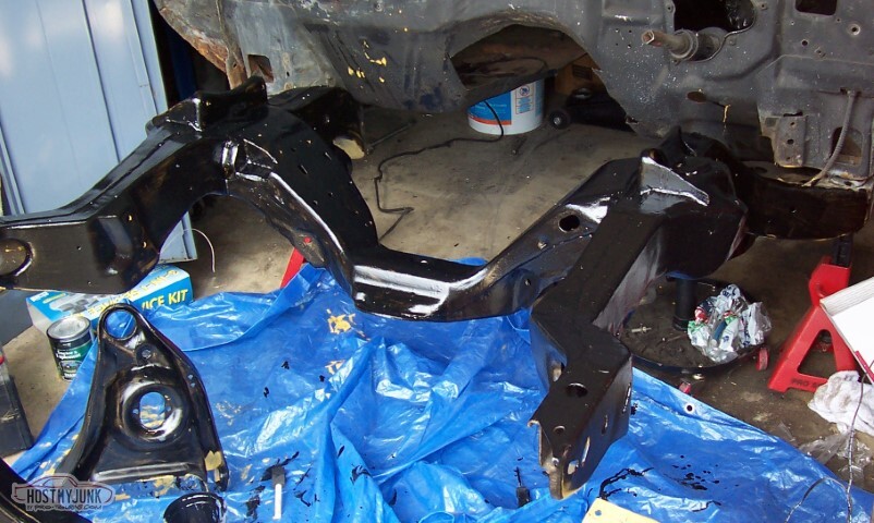
We used a roller for part of the second coat, it helped a lot. I'm not all that happy with how the paint came out in general. I probably should have sanded the primer before calling it good, and like I said above, would have been a lot better if I'd sprayed instead of brushed.
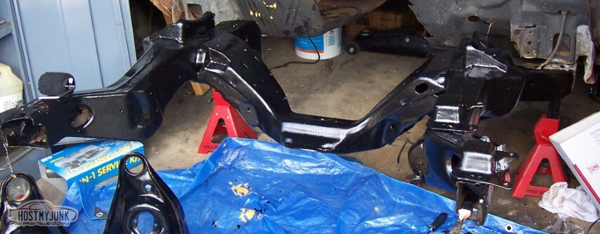
Attached the engine mounts to the frame in their new location, with nice and spiffy grade 8 bolts. Frame is ready, except for the whole lack-of-suspension thing.
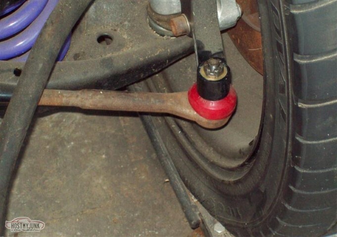
So we assembled the tie rods. The centers are the Hotchkis tie rod sleeves - I bought these used a couple of years ago, nice to put them to use... and I bought the boots with the proceeds from returning the worn bushings to Autozone.

Found a problem with the new lower ball joints -- they're not the Moog problem-solvers repackaged; they're a loose fit. I welded them in, don't reckon they're going anywhere. (went back and welded more after this pic)
Upper control arms are on order. Once they're here, I'll install the springs and spring adjusters, as well as the LCAs and some shocks.. I still have to figure out the proper shocks to use, so the shocks I install will just be the red-ryders I had before.
-
05-15-2021 #22
-ɹoʇɐɹǝpoW-
- Join Date
- Jul 2002
- Location
- Mesquite, TX
- Posts
- 4,901
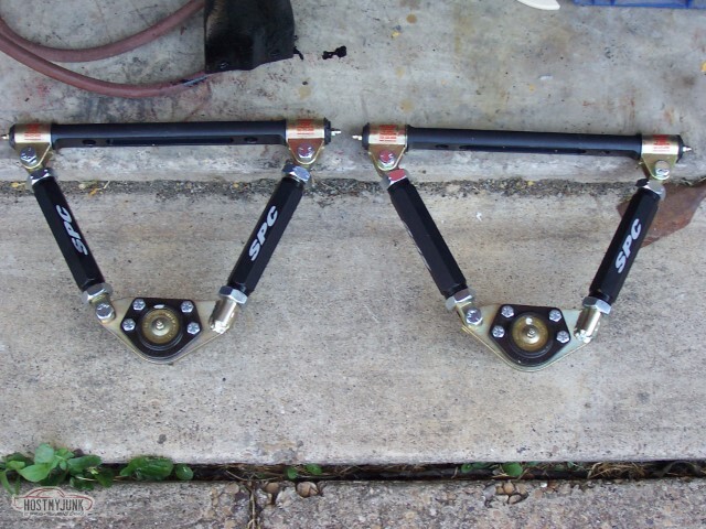
Most of the remaining bits for the suspension have shown up.
The SPC UCAs are very pretty. However, if you'll note here, they're assembled wrong. The welded part of the UCA mount should be towards the front, and all the bolts should be facing down. I should have noticed this before I assembled, for here one of the UBJs is in upside down. Not too hard to correct, but I'm surprised they came as two rights (shrug)
In order for the UCAs to clear the gussets, the gussets need to be cut back on the leading edge (here, shown by the silver paint)
In this picture, the driver's gusset is cut back but I haven't cleaned it up yet.
Here is after the cleanup on the passenger side. I have not repainted the parts that got stripped yet; there's more paint damage on the frame to come, I expect.
Once the gussets were ready, the next step was to mount the LCAs. I don't like how much effort is required to move the passenger side arm -- it was a bear to even get the bolt holes to line up. It does move, but I don't know if it gets me the equivalent of a higher spring rate on that side.
 </td></tr>
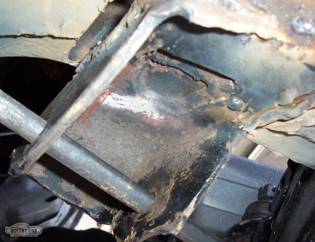
I suspect that when I got the LCA mount reattached 8 or so years ago, they didn't quite get it in the right place. They sure didn't make any pretty welds. I am not sure what I will be doing about this; for now all I've done is not reinforce the LCA bracket -- if it needs to move, it'll come free, I reckon. It's likely that it was "close enough" with the old rubber bushings, I guess we'll see how well it takes to the new ones. If it tears free again, I'll weld it again myself using the new bushings as a guide.
I also cut more of the firewall away for the day that I install the engine again - it appeared to have some interference with the top of the transmission; that won't be a problem now.

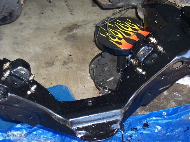
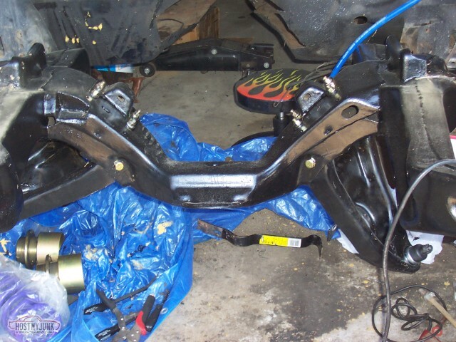
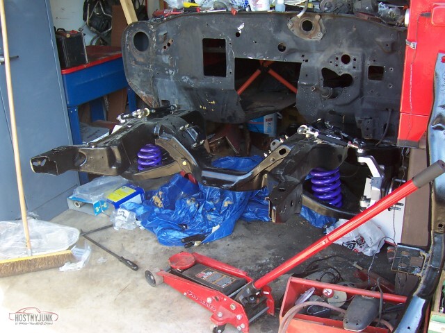
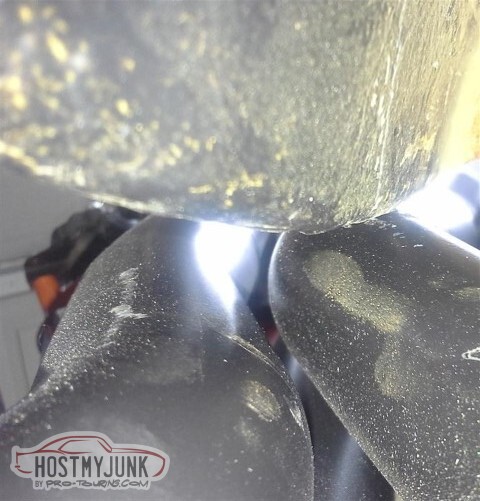
Here it all starts to come together -- the spring adjusters with the Pro-Coil springs (I believe they're 750lb springs), the SPC uppers, and the AFX spindles with C5 brakes. The adjusters are set to roughly half their travel and have been lubricated with a Molybdenum Disulfide grease.
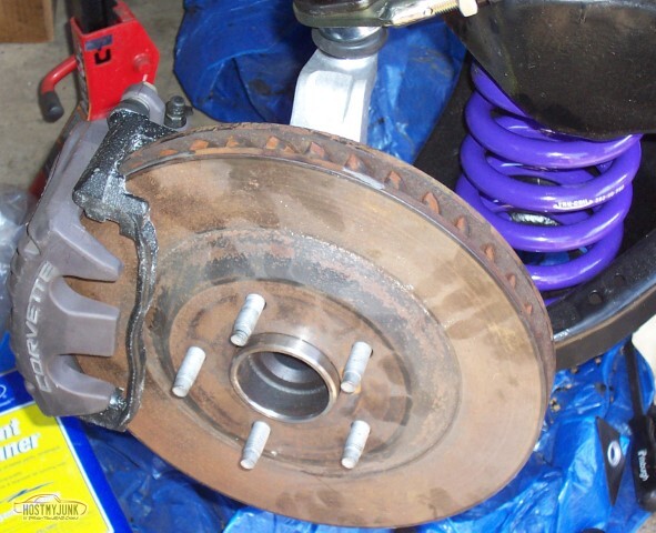
These are the same brakes I was planning on using when I had the tall spindle setup, the rotors have got some surface rust but not a lot but I don't know what the white speckles all over the abutments are. I do not have the pads installed yet, I figure I'll do that waaaay down the road.
 </td></tr>
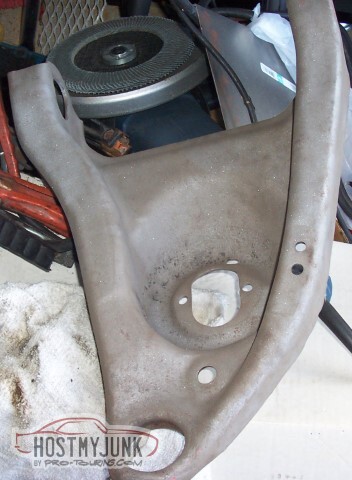
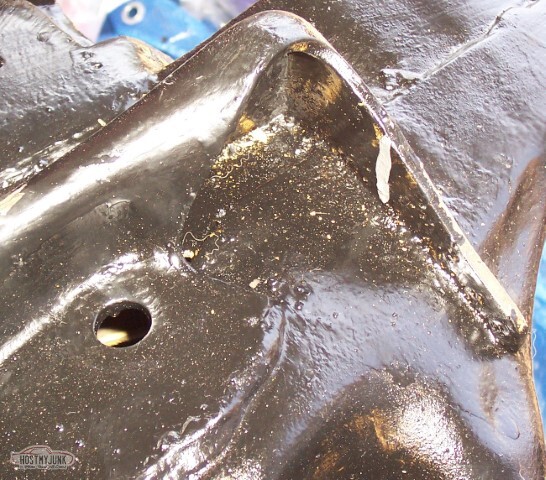
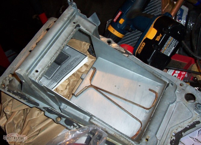
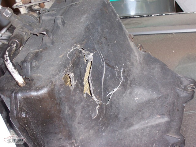
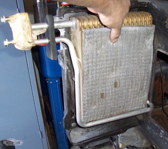
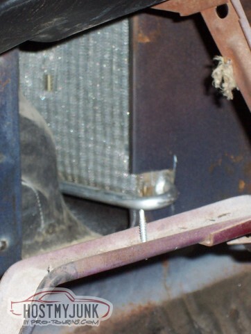
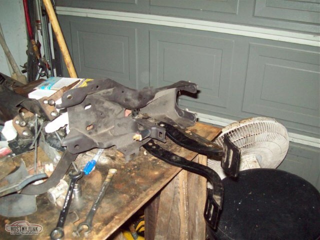
I've bought a new heater core, so time to start tearing down the AC box to install it. I don't really know what all is involved in this other than replacing the seals, and the rebuild kit I bought years ago doesn't really have much in the way of instructions. I expect that it'll just be to sandblast what's rusty, lubricate what pivots, and paint what's raw.

Here's the tub where the heater core goes. A hose and some scrubbing here, I reckon.

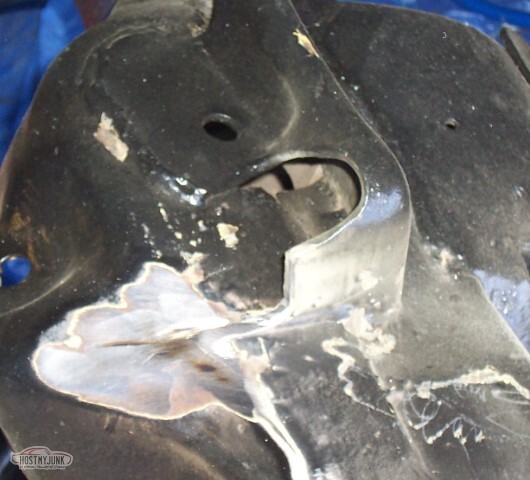
Heater core mounts here. Not sure what the straps do; I took the wrong screws out first apparently. It'll probably become self-explanatory soon, they probably wrap around the core so you don't directly screw into it.
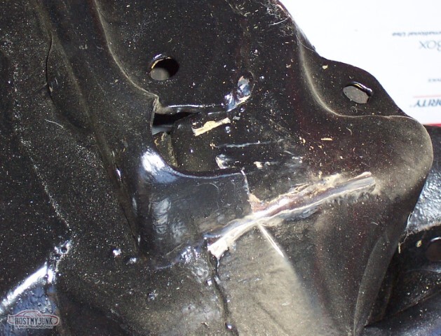
This will be the hard part of the evolution. It might be easiest to find a replacement suitcase, or at least this part of it. Current plan is to use fiberglass to repair, and then to paint the suitcase.
I still need to find some replacement hose for the interior -- mine is old, and shot.
The rest of the front suspension is on hold. While I've got a new idler arm and a new center link (not yet installed), and as you saw in the last update, the tie-rods are ready, I do not have a steering box - I don't plan on using the original, 40 year old box; and I haven't bought a replacement Grand Cherokee box yet.
I also no longer have the tires that go on the front wheels - the unfortunate side effect of them being the same size as the Camaro is that when the Camaro needed tires, the El Camino gave its up. I have one damaged tire from the Camaro that could be put on the Camino's wheels, but the other blew out and was discarded. Not sure what size wheels the car will end up getting, so I'm not so interested in buying a new tire. I'll need to start shopping the local used tire places looking for one more tire.
I've ordered the polyurethane body bushings, they're expected to arrive next week. I won't be installing them until after the Camino is on its wheels -- I don't like using the type of force I expect to need to break bolts (or break bolts free) from underneath it when it's just on jackstands.
The rebuilt dual-disk McLeod clutch has returned and sits, still in the box. Still got a ways to go before mounting the engine though; I want to get the excess holes on the firewall filled in first - the only extra I know of right now is the fuse box, I'll have to get things bolted up first to know for sure.
Still need to get a replacement shifter for the transmission -- B&M's "lifetime"warranty doesn't apparently cover them if you don't have the receipt and they aren't interested in sending me the two dollar plastic ball to fix it. I'll call them one more time, and if they don't step up, I won't be buying anything else from them, ever. Also need to get a reverse lockout solenoid -- both of these items had failed on the Camaro, and the El Camino appears to be a convenient donor for when the other car needs specific parts. The AC compressor falls in the same category, sort of; the one from the Camino was tried but also didn't work... so I know it's bad.
05-15-2021 #23
-ɹoʇɐɹǝpoW-
- Join Date
- Jul 2002
- Location
- Mesquite, TX
- Posts
- 4,901
I did a lot of cleaning up -- got the last of the inherited tools put away and the garage clean enough to work in.
I also got to the point where I was ready to start cutting the LCA mount off - and I was really, really nervous about doing such a thing. Go figure.
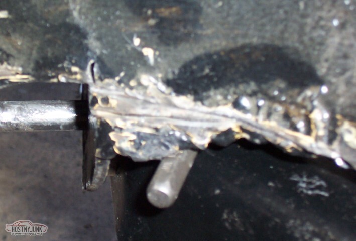
Here you see the mount, and the test-rod that points out that it's not in the right place. Theoretically, the rod should slide through the front mount holes, and then through the rear mount holes. Here, it hits the upper right corner of the hole by just a little bit.
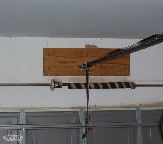
Sunday when I came out, the door wouldn't open. Guess that spring does more than I would have thought, I just couldn't lift it -- and no door means no work, since the garage is very cramped and where I was working really needed that access.
Might be just as well, it was very hot out.
Okay, I have no pictures from the first part of this Saturday. I don't know if I failed to take any, or the camera failed to save them. Given that it no longer turns on, I'm going to go ahead and claim it to be the camera's fault. The day started with the ceremony of the cutting off of the suspension bracket. What a pain. I used the 9 inch grinder with the cutoff wheel where I could, falling back on the sawzall where I couldn't fit the grinder. I only had two metal cutting blades for the saw though, so when they were done, I was done with the frame and had to move on to other tasks..
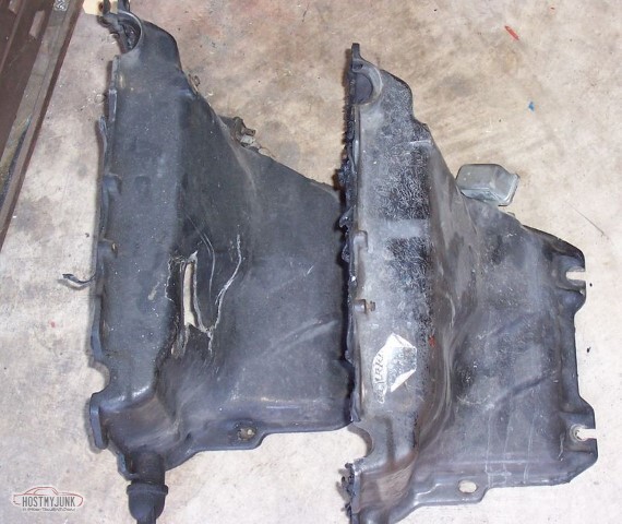
The broken AC box? The spare 70 AC box in the attic was identical, except for the broken part.</tr>
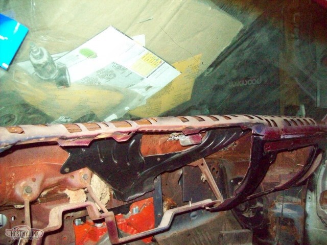
This bracket that held some piping had to go.
Started to try to mount the Camaro AC coil by notching the box to fit the tubes.
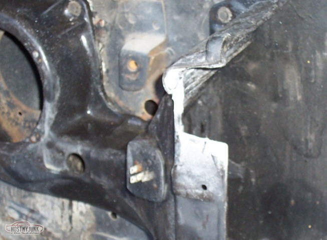
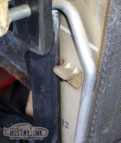
This tab is a problem, but was easily bent down (hope I didn't poke a hole in things when I bent it though)
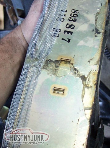
There was a tab here on the other end of the coil -- could have sworn I took a pic, but I don't have it now -- but the tab is just attached with clear goop and it came off easily enough.
Here's how it fits with the tab bent.
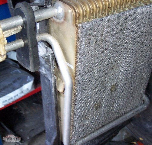
Not such a good fit, that pipe is in the way.
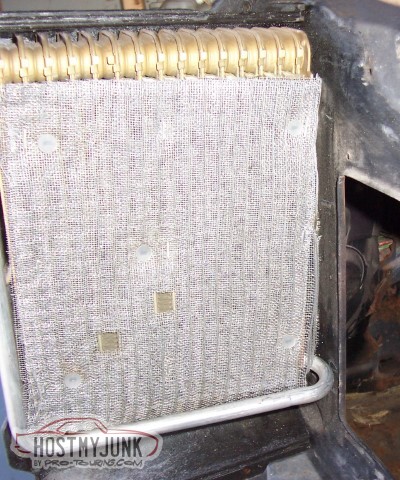
Notched the firewall to clear the pipe. I'll have to also notch the inside box.
Closed the whole thing up. I'll have to block off the bottom part of the box -- this coil isn't nearly as tall as the original.
Moved on to the clutch. I'd sent the dual-disk off to McLeod to get rebuilt, and I have it back now.
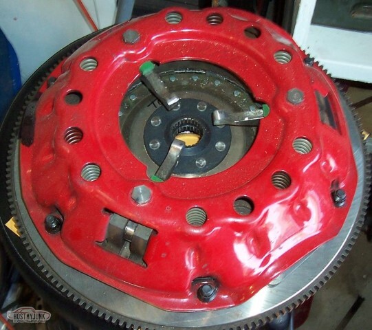
I'd picked up some ARP bolts for the flywheel.
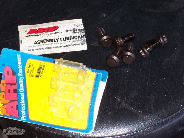
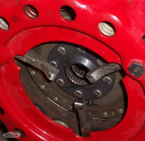
After disassembling the clutch, it was simple enough to attach to the crank with those bolts.
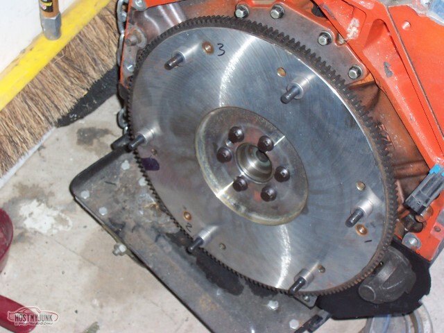
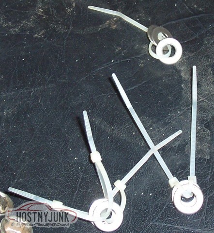
Disk 1, and then the floater plate. The numbers written on the flywheel? They identify which group of spacers and shims go there.
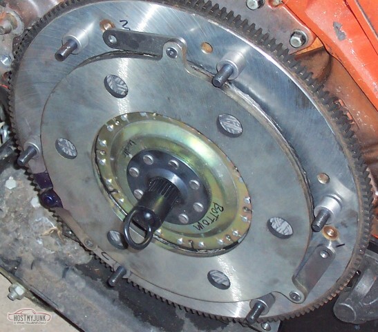
Spot 1 is the group with one nylon tie, etc. The spacer goes on the flywheel side, and then the shims closer to the floater.
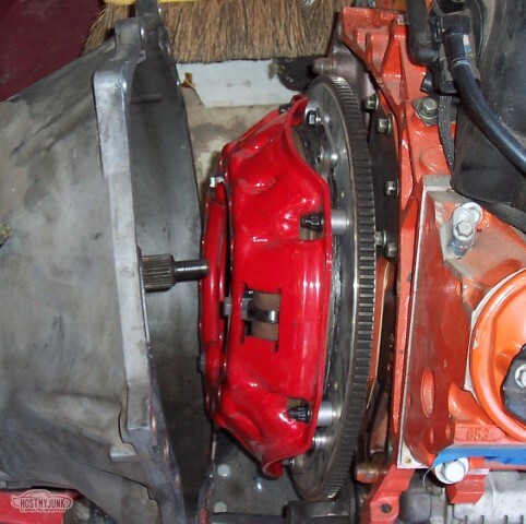
Assembled.
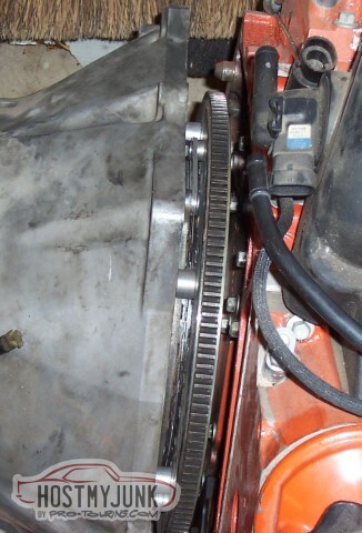
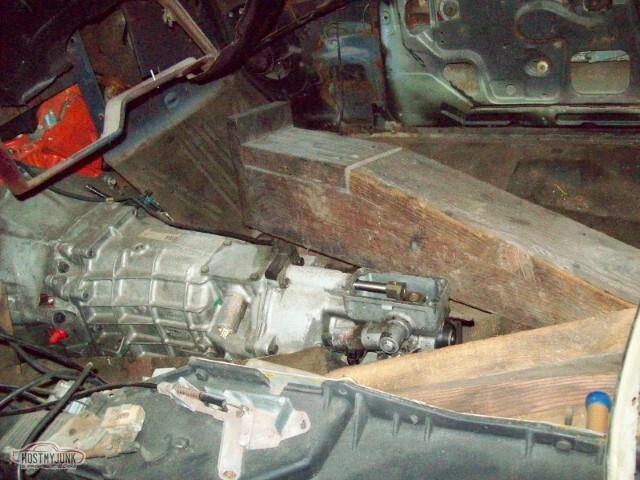
Hurrah for transmission installations.
Except when you can't get them to line up. I've torn this apart a couple of times and tried to get the boy to help get it in there, and it just isn't working. Will continue to try once the engine isn't sitting in a nose-down state -- that complicates it a bit.
Sunday. Saturday night I went and picked up new blades, and the rest of the mount came off within a matter of minutes. Sharp blades are a good thing.
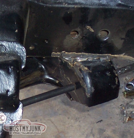
Here the mount is just held in place by the rod and the LCA (LCA is on a jackstand). Amazing how easily the LCA moves when the mounts line up. The difference, for the most part, was that the LCA needed to be moved back on the frame about 3/16".
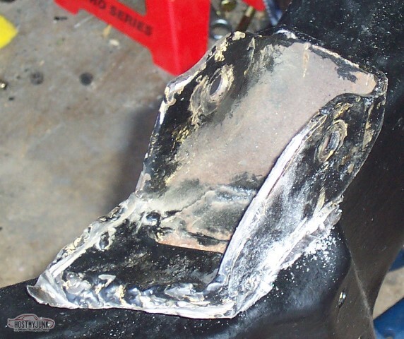
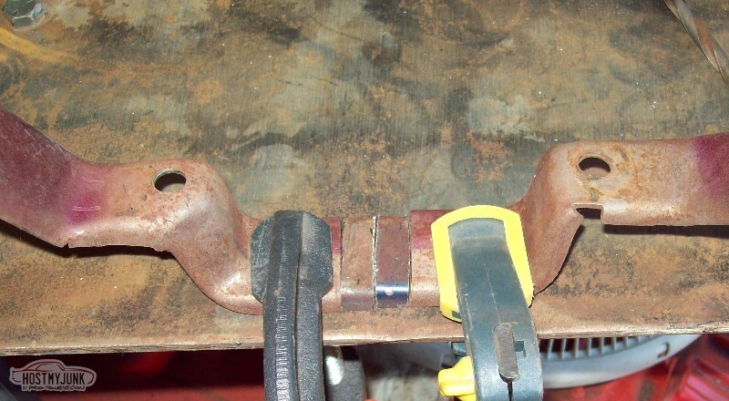
On the outside, used a punch as a spacer to put the mount in the right place for tack welding.
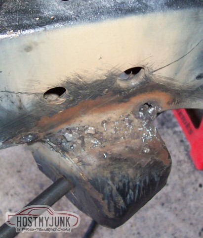
The MIG is still set up for .023 wire; the TIG is not driven by thick enough power cables to put forth enough juice for this, which leaves stick-welding, which I suck at. I am not too worried about penetration -- I blew through enough that I can be pretty sure I'm melting the metal, but I a) leave some ugly welds, and b) have to clean up a lot of blowthrough. The inner and outer edges of the frame are mostly welded. I think I've had some warpage from the heat, the rod still slides right in but it gives some resistance to turning. I'll need to put the LCA back in and verify all is still well (didn't want to do it while everything was hot, hate to melt those bushings)
The fore and aft edges of the mount are not welded. I'll have to make some bits to fill in the gaps -- both edges have some area to fill.
In the back, the gap is about 1/8";. The front gap is more like 3/16" or 1/4";. I had to stop welding because the stick welder puts out some interference that was ruining some stuff other folks were doing. Plus it was really hot with the welding gear on, so I think I was happy to stop.
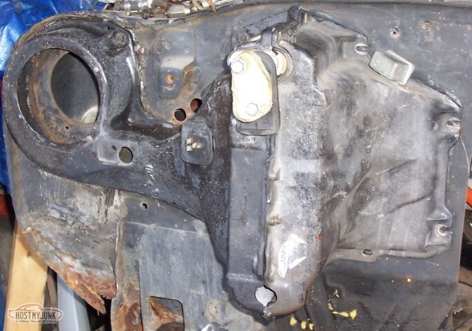
Here's the AC box from the inside.
Personal self-improvement list: Measure more before just cutting things. I think once I started cutting on the car, it became too easy to just cut things -- frames, tunnels.. where does it end?
05-15-2021 #24
-ɹoʇɐɹǝpoW-
- Join Date
- Jul 2002
- Location
- Mesquite, TX
- Posts
- 4,901
I bought El Camino parts!
No pictures, because I'm either a jerk or I didn't take any. Or both.
I got:
- Jeep Grand Cherokee steering box so I can complete the front end assembly
- Camaro clutch master cylinder w/ ATS bracket so I can mount my clutch
- A clutch pedal assembly so I can activate the clutch
- MSD fuel pump
- Fuel sender that has a return line, so I can use my stock tank
- Both panels that form the sides of the cowl, because mine are rusty (you've seen the pics)
This *should* complete my fuel system (other than connectors), the front suspension (other than shocks), and the clutch setup. Still can't get the transmission mated to the engine. Current thinking is that it's because of the cheapie plastic alignment tool just isn't good enough to use for the dual-disk setup. Forte's is out of the GM metal alignment tools (I was supposed to call today and see if he was able to get a Ford one turned down) and my local QuarterMaster dealer doesn't have the 26 spline one.
I did grab that Reverse Lockout I'd "borrowed" from the Camino's T56 and the Pro 5.0 shifter, returning the stock parts to the Camaro.
I also bought tools!
I bought a bunch of little tools I'd been needing. I spent hours at the new local Harbor Freight just looking at what they had and there's always some little thing that you never knew you'd need. I got things like a set of J-nuts and screws (which I've already used), heat shrink assortments (I've used that too), fuse holders (they were on clearance!) and little crap like that.
I also got the bandsaw I've been needing, and a throatless shear -- I haven't used the bandsaw yet, but that shear makes cutting metal easy.
05-15-2021 #25
-ɹoʇɐɹǝpoW-
- Join Date
- Jul 2002
- Location
- Mesquite, TX
- Posts
- 4,901
The mounting of the transmission to the engine took place over the holiday break. I had a lot of issues -- starting with the inaccuracy of the cheap plastic alignment tool. A post pointed at Forte's as having steel tools that would do the trick, but they're out of them. Someone else suggested just taking the bellhousing off, and using the input shaft as the alignment tool - so that's what I did. Transmissions are heavy.
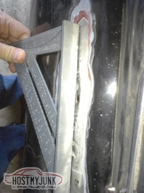
After repeated failures, I figured out what was going on... when I was feeling the shaft mesh and go the rest of the way in, what I was actually feeling was it clearing the second disk. When the measurement from the flywheel to the transmission face is roughly 5 1/2 inches, you're not in the pilot bushing. Once I figured that out, it went together easily - about 4 5/8" flywheel to tranny face measured on three sides to make sure it's centered, and angle finder used to make sure it's not crooked. Bolted together just fine at that point.
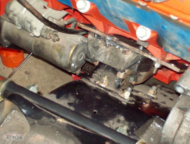
Today was the ceremony of the putting in of the engine. It went pretty well, and the engine hoist is now disassembled and placed in the attic.
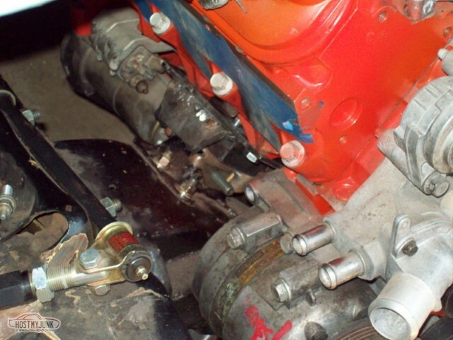
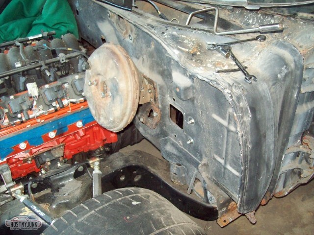
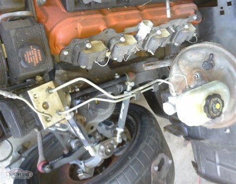
I need to grind the rear corner of the steering box to clear the alternator. I also need to clean or replace the alternator. Steering box needs to come out anyway, I've broken two pullers trying to get the pitman arm off. I figure next step is to turn it upside down and use the press on it. While it's out it can be ground and painted. Belt clearance looks tight, but it's not so bad.
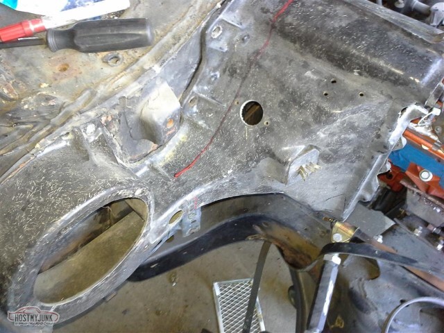
Okay, this was unexpected. The notch that I measured over and over again before cutting? Not even close to big enough. I'll have to take the compressor off and cut more.
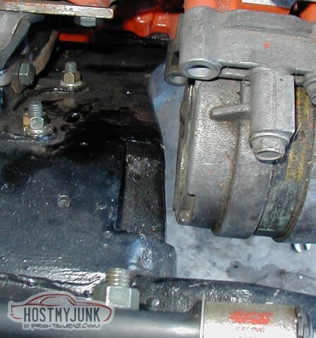
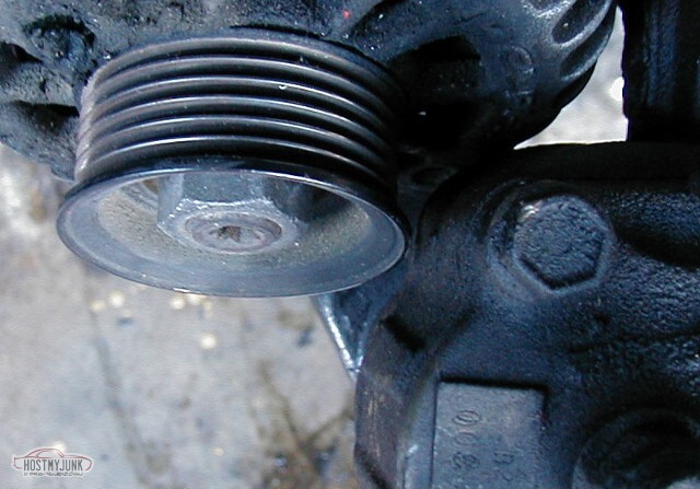
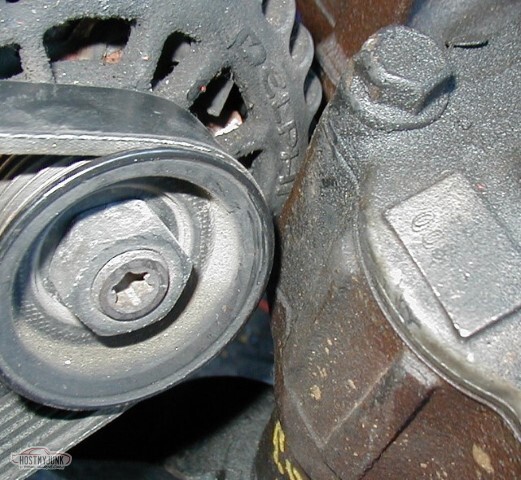
With the belt on, you can see the clearance a little better... there's probably 1/4" to 3/8" between the belt and the steering box.
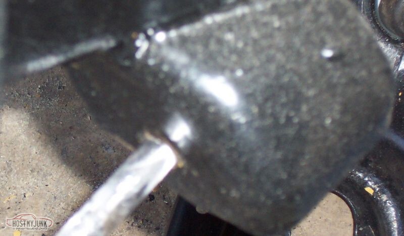
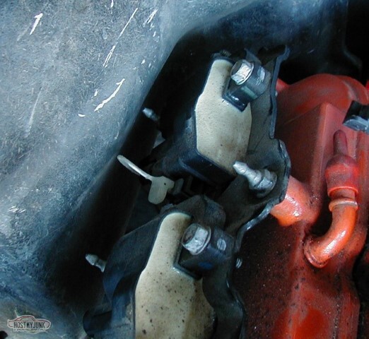
I'll need to replace these pointy coil bolts with non-pointy versions. I should probably also put the plug in now before I mount the AC box. Perhaps the box should be clearanced a bit.
Final pic of the engine in its new home. Bolts are in but not tightened.
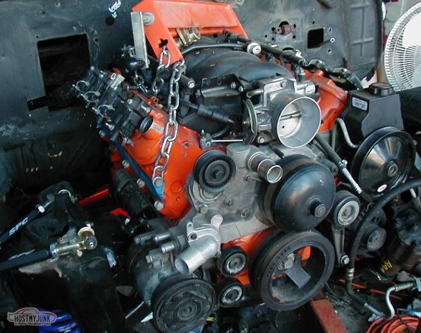
Between the slope of my driveway, the huge gap between the driveway and the garage, and the lip at the garage entrance, moving the engine around takes a lot of effort. If the weather remains nice, I should be back out there in the next few days.
Next up, either AC line clearancing or steering box... and then the car goes back on its wheels. Still to come: Gussets for the LCA mounts, sway bar mounts, transmission mount.
05-15-2021 #26
-ɹoʇɐɹǝpoW-
- Join Date
- Jul 2002
- Location
- Mesquite, TX
- Posts
- 4,901
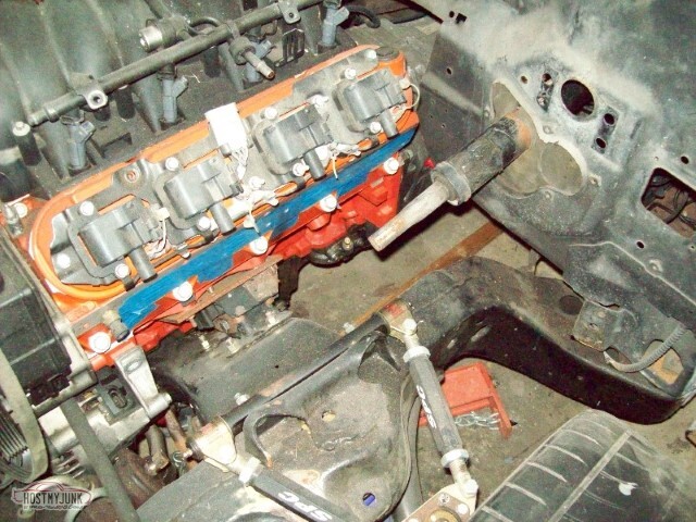
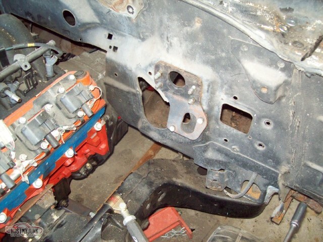
Engine is bolted in on the El Camino. Driver's side:
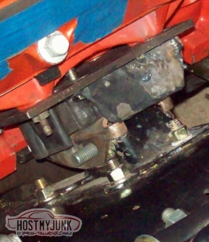
It's wierd; pretty sure I sandblasted, primed, and painted the mounts here.. but they're all sorts of scarred up. Good thing this isn't a show car.

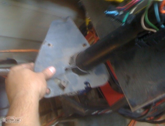
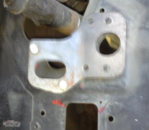
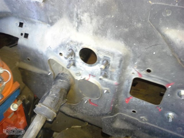
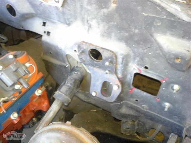
<tr><td>I had to adjust the passenger side mount to move the engine bolt holes back some (arrows show direction). Since bolting this to the block is the first step, distance wasn't so important -- but I believe it was roughly 1/2 inch.

... and here it is, bolted to the block, mount attached, and welded to the plate to fix the relative position.
Unfortunately, there's a problem: The bottom bolt hole doesn't really line up with anywhere that there's "metal" to bolt to. I'll have to use this plate as a template for a new one, or weld more metal along the bottom.

Ran into a minor snag with the clutch bracket; the hole in the firewall doesn't really line up with where the shaft wants to go. Will have to cut a new hole, not sure yet how I want to seal it to the firewall.
Engine mounted with the bad pass bracket. Level, straight, ready to move on once I a) fix the plate, and b) fix the notch for the AC lines.
05-15-2021 #27
-ɹoʇɐɹǝpoW-
- Join Date
- Jul 2002
- Location
- Mesquite, TX
- Posts
- 4,901
I do not know how many times I've had to rework these motor mounts, or how many times I've chosen to rework them, or whatever perspective you want to have on them. Hopefully this will be the last time. If I get the motor mounts finalized, then the next step (I suppose) is notching the frame (correctly this time) and bracing the LCA mount, and then I can put the core support in and get a bit further. Whee!
Oh yeah, somewhere in there I need to do the body mounts too, I have some poly mounts to put in. And I have to figure out the brakes, and the steering, and I think I was missing a rod boot on one of the tie rod ends, and I have a lot of cotter pins sitting around so I think I have failed to do something there. The list goes on and on.
I'm starting to see a trend here -- the allen head bolt is grade 10.9, but they still strip out. I am not sure if this is the second or the third that I've had trouble with.
When the replacement bolt goes in, I reckon first I need to chase the threads with a tap, and then use antiseize.
The regular bolts don't seem to have any problem; I guess it's something with the coating or something.

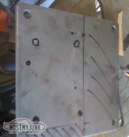
The plate is marked for the new motor mount. I imagine I'll end up cutting it tomorrow, and I do not doubt that I'll have to notch the bottom to clear the engine's ribs. Whee.
I have a problem, apparently. I had a hole in my AC box. I came up with a replacement to fix the hole.
I then promptly broke the replacement as well.
05-15-2021 #28
-ɹoʇɐɹǝpoW-
- Join Date
- Jul 2002
- Location
- Mesquite, TX
- Posts
- 4,901
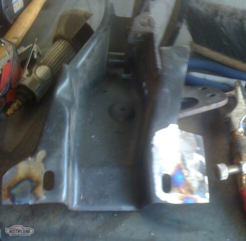
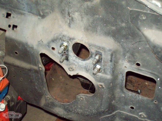
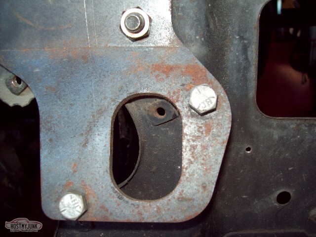
The new motor mount plate is ready. The holes for the stock mount are already drilled and tapped, just waiting for the mount to be attached.

And here the bolts are tightened down, the engine is lowered into place, and the long bolt for the mount has been installed. At this point, other than putting washers and nuts on, the engine/transmission are installed. (Okay, to be truthful, the bolts on the transmission mount aren't tightened down yet, but that's trivial).
Once I get the frame notch for the compressor lines done and the LCA reinforcements in place, it'll be safe to install the core support.
The other thing I've done lately is to build a welding table - 1/4 plate top, frame/legs built out of 2x2 box tubing. This will make things easier.

05-15-2021 #29
-ɹoʇɐɹǝpoW-
- Join Date
- Jul 2002
- Location
- Mesquite, TX
- Posts
- 4,901
Know first off that I couldn't find my camera, so I had to take pictures with my phone. Know also that the iPhone takes crappy pictures.
2021-05-11 edit: This would have been the iPhone 3G, circa 2010
The 4th gen Camaro column I'm using is different from the original El Camino column. The spacing on the bolts near the wheel is wider - roughly 6" rather than the roughly 5 1/4" the original column used. Also, the Camaro column has a different mount at the firewall, though the diameter of the column is about the same.
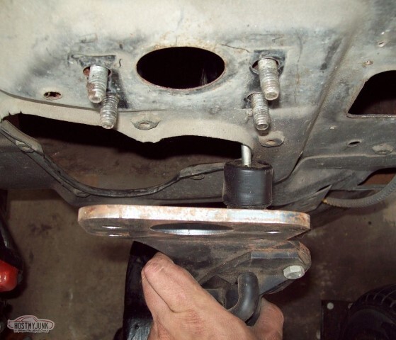
So - started today by cutting around the flange for the bottom mount for the column. You do not have to go very deep here, the flange is very thin. I went too deep, but not deep enough that I am worried about the shape of the remaining bits.

The El Camino flange fits just fine, although I am not sure how it should be oriented here. I also don't know what size the bolts are for the clamp; they're smaller than the 1/4" bolts I had to play with.
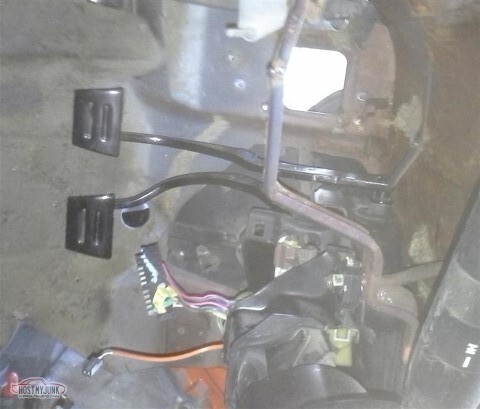
Since the bolt spacing at the dash is wider on the Camaro column, I needed to widen the bracket for the brake/clutch pedal.
Apparently I needed a reminder that recently welded metal is hot; after I set myself on fire I stopped for the day.
So I still need to drill the pedal assembly, find bolts for the column base (and I suppose the scored bit of the insulation is the part I need to open up for the clutch pedal), and modify the bottom part of the dash. Then the column and pedals can be mounted.
I also looked at what modifications I'm going to need to make to the Camaro's brake booster. They are... substantial. I might be better off coming up with a regular El Camino booster.
05-15-2021 #30
-ɹoʇɐɹǝpoW-
- Join Date
- Jul 2002
- Location
- Mesquite, TX
- Posts
- 4,901
(side note, relevant but not specific to the El Camino. Including because hopefully I'll need this information soon)
LS1 Tuning with EFILive
Ok - so new vehicle, a functional LS1. Car has longtube headers, ported MAF, a giant K&N setup, and true dual exhaust (3 inch through an X pipe, dumping before the rear axle)... and it has the stock 98 TA tune. That won't do.
I've claimed several times on this site to be an idiot, and that applies here as well. I ain't an expert on this, but I did drive past a Holiday Inn Express earlier today. I have the level of experience one gains by doing this once.
Obviously the first step was to do the basics -- turn off EGR and AIR, disable CAGS, disable the rear O2 sensors, disable all the emissions that might later throw a code. That's simple stuff; I did all that on my old Z28 as well.
This EFILive document details how one does a Calc.VE tune. Next step was to calibrate the MAF. That was relatively easy -- it worked out to roughly a 10% boost all the way through.
Next up needed to install the wideband O2 sensor (an Innovate LC-1 that I've had in the box on the shelf for five years now). A few interesting learnings from that -- and the reason why I actually added an update for this work -- follows.
Per the instructions, red goes to a switched 12v source; black goes through the calibration button and through the LED, then to ground.
Blue and white go to vehicle ground. They do NOT connect to pin D of the Flashscan.
If you have a FlashScan v2, you can use the WO2AFR1 and WO2AFR2 PIDs. If you have a v1, like I do, those PIDs don't work -- you have to use EXT.AD1 and EXT.AD2 to get the raw voltages, and BEN_LC11 and AFR_LC11 (for connection to pin C) or BEN_LC12 and AFR_LC12 (for connection to pin E).
With the LC-1 itself - a few things there, too:
- The headphone-looking plug things have to go farther in than you'd think to connect.
- The LM Programmer program and the LogWorks program don't coexist well. You may have to reboot after closing one to get the other to work.
After using the Programmer, trying to run LogWorks may give an error about a lack of realtime data. - If you find the values in LW to be bouncing around all over the place, redo the free air calibration.
- Don't ever, ever, ever short the yellow or brown wires to anything, it'll ruin the device.
- Calibrate the device to your Flashscan by using LM Programmer to set both the min and max for channel 1 to 3.5v, and the min and max for channel 2 to 2.5v. You can then compare with the voltages reflected in EFILive to verify that you're getting what you should be getting.
If'n you get lost, or confused, don't be afraid to go hit the EFILive forums. They're very helpful.
I still have work to do; I haven't done anything that involves full throttle tuning (hell, I've floored the car a whopping twice in the whole time I've owned it; not convinced yet that I trust the car enough to beat on it).
05-15-2021 #31
-ɹoʇɐɹǝpoW-
- Join Date
- Jul 2002
- Location
- Mesquite, TX
- Posts
- 4,901
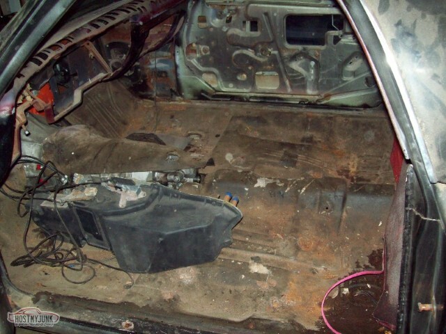
Interior upholstery removed. It would appear that somewhere along the way, the cab became a storage location. I have, among other things, wooden ramps in there.
Alternate view of the dash with no pad and no dash and no column and no glovebox.
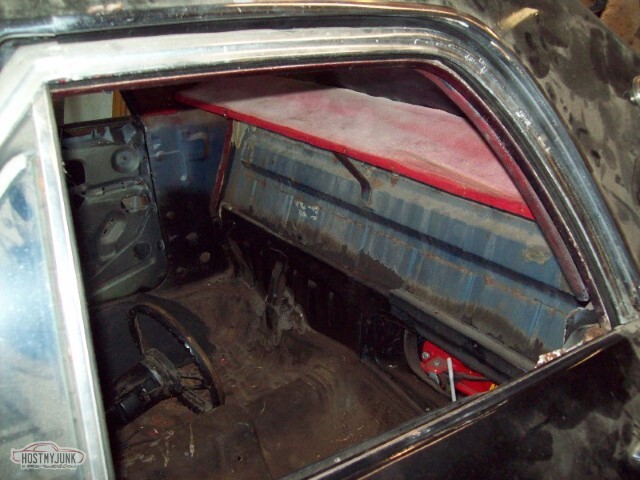
So I took the new column and just hung it off one of the bolts to get some sort of idea. This was not as helpful as it sounds; all the angles are completely off since it's not in the proper place.
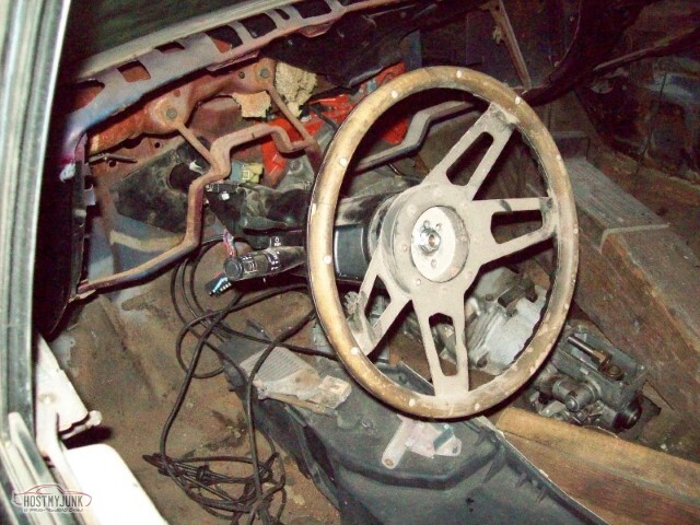
It's not a good angle for the picture to see the angle of the shaft but it's aimed far too high. Makes sense since the cab-end of the column is too low.
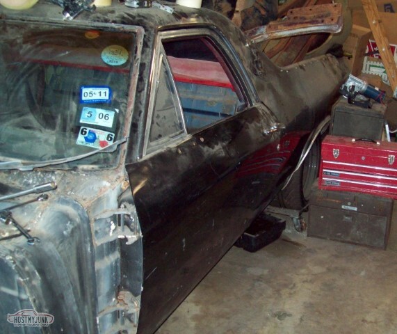
So while i was at it, after doing things wrong with the column, I got carried away while removing the windshield trim and ended up removing the windshield too (just as well, it was cracked and as you can see, the top of the dash desperately needed paint). That's red, I think, from three or four paintjobs ago.
So next order of the day: Make the holes in the pedal assembly wider so that they'll fit the newer column (you might remember I mentioned this before). Initial try was the drill press. That worked poorly.
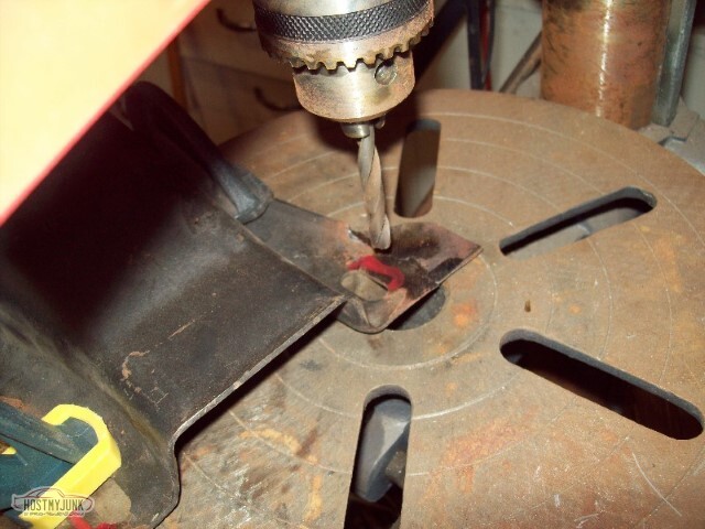
So I tried the air saw. That worked worse as it broke one of my new ears off.
Rewelded.
So I pulled all the useless crap out of the interior (except the AC box as I don't know where else to put it and in theory I'll attach it to the car shortly)
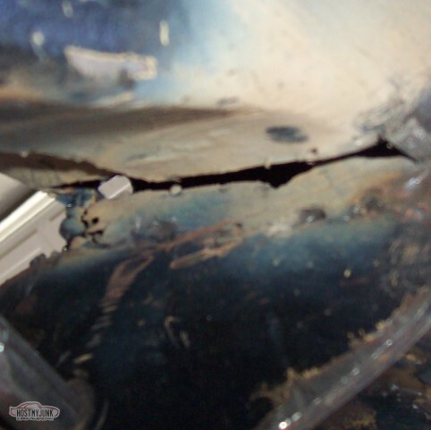
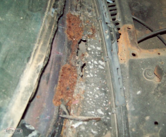
So I have more rust - passenger side cowl, right where the windshield mounts. Not a big deal, it drains into the cowl just like everything else up here, but needs to be fixed anyway.
So the bottom of the dash is too narrow to fit the widened pedals, and the holes are too narrow for the newer column. I cut the middle of the dash out with the intention of taking ~1/2" from each end and putting them in the middle, to widen the unit without changing the overall dimensions. Here we see the ends ready for welding. Note: Plastic clamp is a bad idea for welding.
So with the dash-middle out, time to mount the pedal-assembly. Just threw washers and nuts on it for now...
... and something bad has happened.
a) The bolts are too short (the pedal flange is > 1" below the dash bottom)
and b) the bolts aren't in the right place.
They seem to be OK for the dash itself, so apparently the 69 Camaro pedal assembly is *not* the same as the 69 El Camino one. (I also think I'm offset to the right just a little but have not yet measured).
Alternate view.
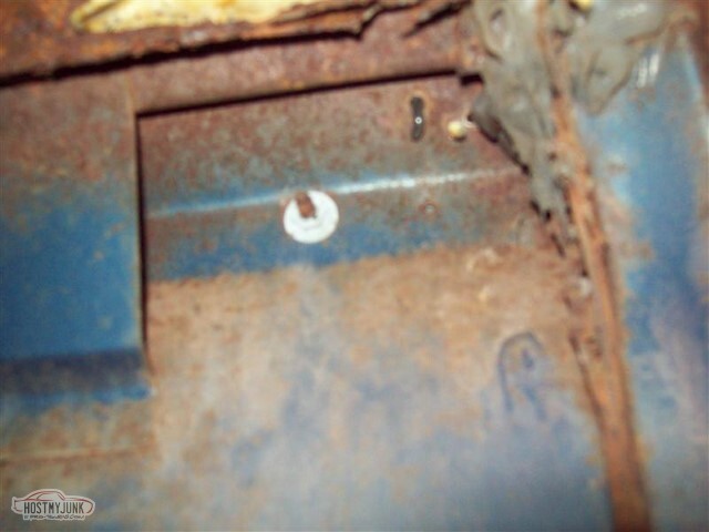
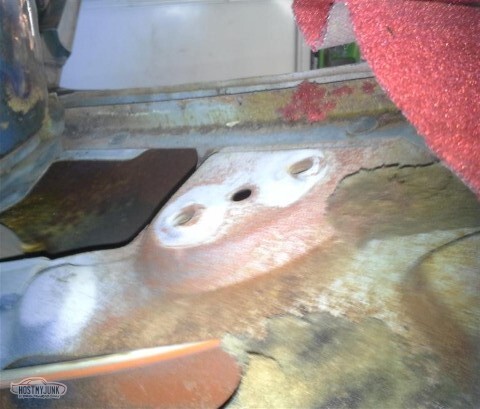
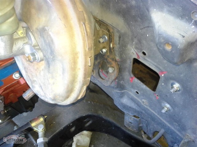
So in the spirit of "let's see what else doesn't work right", put the clutch master cylinder bracket on the firewall. Figured I was going to have to cut a hole for the rod.
Did not expect that the hole I would have to cut would overlap an existing hole. That's.. not good.
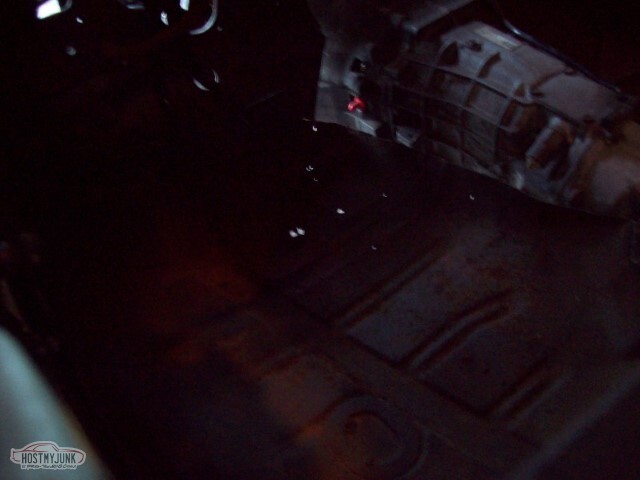
And with the interior cleared out, I could see that I had some rust issues in the floorpan as well (you can't really see most of it with the flash here)
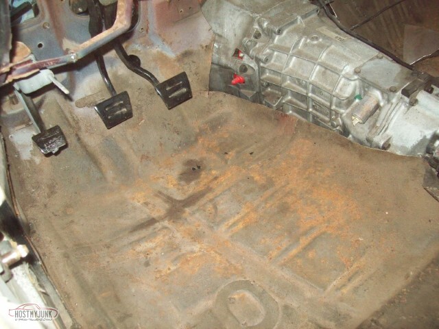
but I bet you can with the flash off.
But, I went ahead and mounted the brake booster and e-brake handle. I know I'll be pulling them back out shortly, but I like feeling like I'm assembling things.
And then I spent several hours getting rid of crap from the garage. Pile in the bed is the inner fenders for both the Camino and the Chevelle, the Chevelle's fenders and I think both core supports. All need at least sandblasting if not minor rust repair.
I pulled the rear carpet out too (it hung to hide the rear panel). It was faded and needed replaced.
So: Column lining up with the steering box is probably not an issue; box is still in the same place and if the column is in the same place then it should still line up.<p>
I figure that on the pedals, I'll notch the assembly in two places to move the front end higher without changing anything with the geometry. Might come up with an alternate plan in there though.
Still need to figure out how to connect the column to the box - looks like the box is splined and the column is just a double-d shaft but I suspect there's going to be 12-15" I'll need to add. I don't want to use two u-joints so I don't really know how this will work -- old shaft was splined and then had a rag joint at the box; that would have worked out great if the new shaft was also splined, but it ain't.
Luckily enough: I don't have to make that decision yet; I'll have to worry about that when I get closer to doing the headers.
On a happy note, I found the missing fuel pump (perhaps I didn't mention that: I bought an MSD fuel pump and then lost it.)
Not sure what's next up after the column gets mounted - rust/firewall repair/rear axle/fuel tank? Body bushings? AC box? I don't know yet.
05-15-2021 #32
-ɹoʇɐɹǝpoW-
- Join Date
- Jul 2002
- Location
- Mesquite, TX
- Posts
- 4,901
So I think I did a lot today, but not a lot on any one specific thing.
With the pedals removed, the steering column comes through like this. I had hoped that I would be able to have just a single u-joint, but it looks like it's going to take two and an intermediate shaft.
and here's what it looks like when the column is in its final position. Not sure if I'm going to use this wheel or not -- this was the wheel in the car for ~20 years but it's showing its age and the wood is starting to come apart; if I'm going to use this, I'll need to rework it.
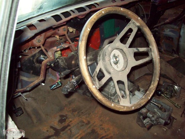
So in order to build a box around the clutch rod, I'll have to fill part of the steering column hole. Here the area that needs to be metal is boxed in.
alternate view of same
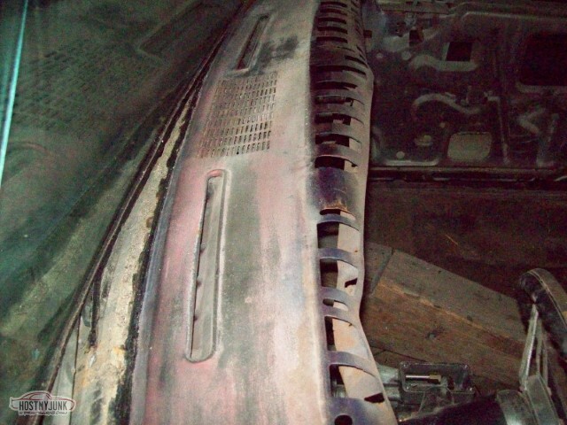
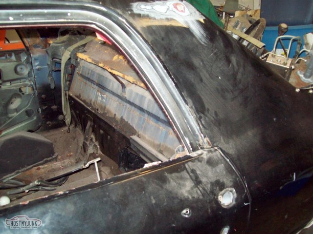
Sail panels removed, pinchweld moldings removed, cover on package tray removed. I do not know what I am going to do about the upholstery. You can see how faded the velour headliner is. If I'm going to replace the roof, this gets easy (ha ha) as I can just get a stock headliner; otherwise, I've got the sunroof in the way.
Cleaned the garage for a couple of hours, found and installed the missing tie rod end boot. Added a washer to the aluminum arms as I just didn't feel right torquing against the pretty anodizing. Washer seemed to fit like it was supposed to be there.
So I realized that I was missing a part in the AC box -- the plate forces the air to go through the box itself and not behind the coil. I had been thinking that I needed to use fiberglass to block off the unused part of the box, but if metal is good enough here, why wouldn't it be for the bottom as well?
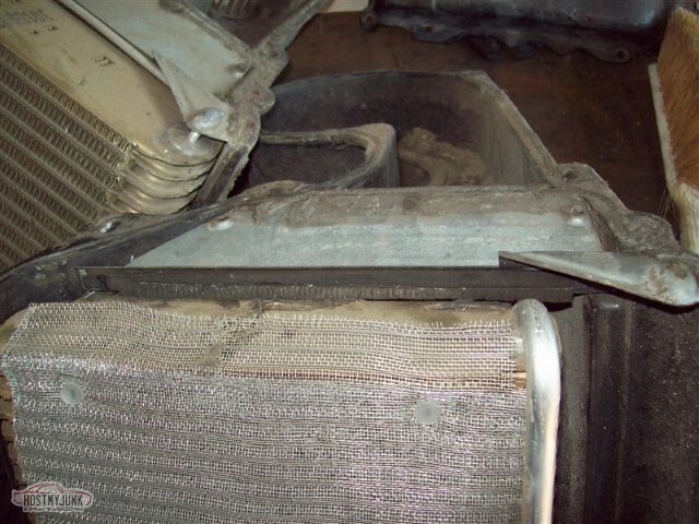
Here's the area that would need blocked
Roughly 2 inches wide. I can screw or glue or something to the flat surface that is between 0 and 1/2" on the measure here.
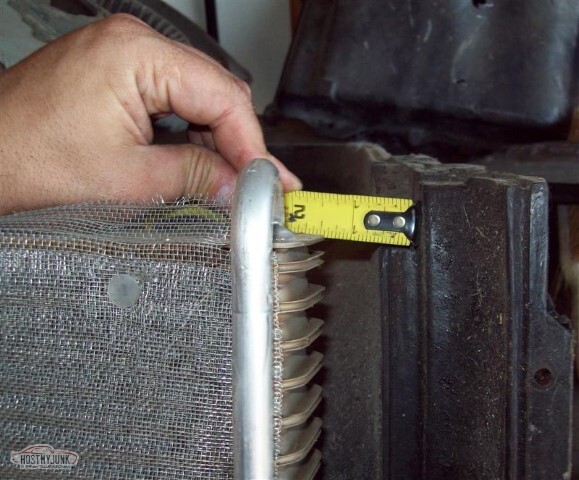
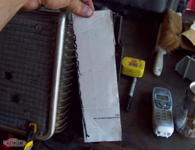
Cardboard template looks to fit perfectly.
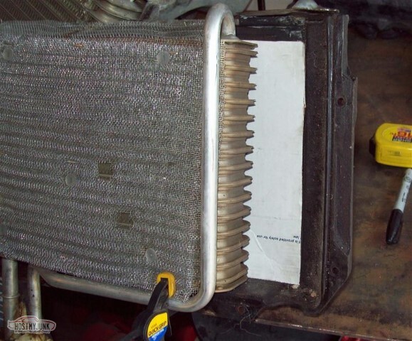
It looks like this. I'll want to prime and paint the plate before assembly so I haven't bothered cutting metal for this yet.
So: What's next?
Well, I know that in the near future are:
- Torque the upper ball joints and tie rod ends (61 and 35 lb/ft respectively).
- There's a bolt missing to attach the steering box to the frame, I'll need to correct that.
- Pedals need to be adjusted to line up correctly.
- Need to complete work on the AC box.
- Still need to correct the AC notch in the frame crossmember.
- Still need to reinforce the rear front LCA mounts (rear front as in the rear mount on the front LCA, not front mount for the rear LCAs).
- There are holes in the firewall that need to be filled with metal, like the fuse box hole above. I also need to patch rust in the floorboards.
- I need to reassemble the transmission tunnel, but in order to be able to properly figure out how much I need to add for the taller tranny, I need to replace the (probably original) body bushings. I expect all of the bolts will break rather than unscrew.
- Then I can move on to big stuff like the rear axle rebuild and the fuel tank
- Somewhere along the way, I need to de-rust and at least prime the body parts sitting in the bed - the inner fenders for both cars, the core supports, and the Chevelle fenders. A sandblaster would be helpful, I think.
- Oh yeah - if I want to complete the front suspension/brakes, I'll need to replace the warped rotor.
05-15-2021 #33
-ɹoʇɐɹǝpoW-
- Join Date
- Jul 2002
- Location
- Mesquite, TX
- Posts
- 4,901
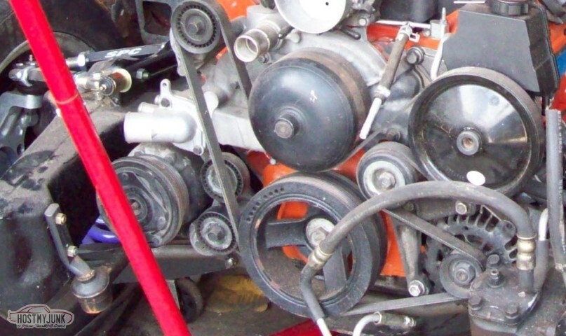
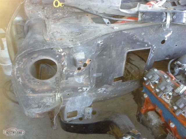
The El Camino had to donate its alternator to the TA, and during that process I realized that I can't remove the alternator with the engine where it is. Seriously. I had to take all the alternator brackets off to get it out. That ain't going to work, so I suppose I need to go with alternate accessory mounting locations (which may make the AC frame notch easier, if I don't have to do it).
05-15-2021 #34
-ɹoʇɐɹǝpoW-
- Join Date
- Jul 2002
- Location
- Mesquite, TX
- Posts
- 4,901
Ok, so it's time to do things. No updates over the past few weeks since (as usual when I don't work on it) I had to spend quite a bit of time cleaning so I'd have room to work.
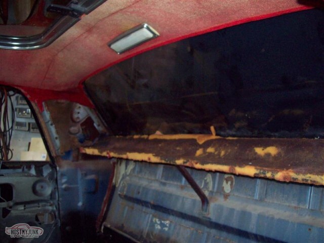
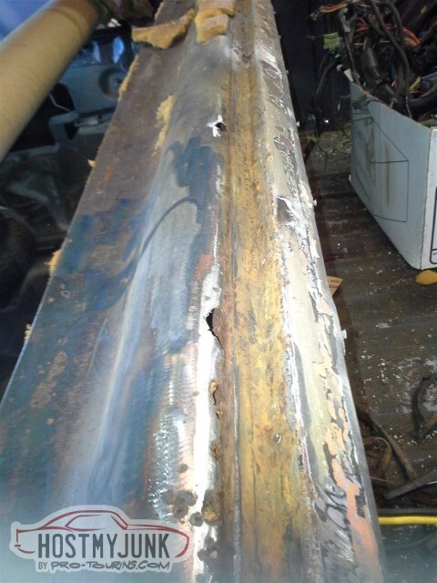
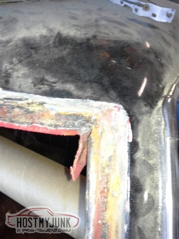
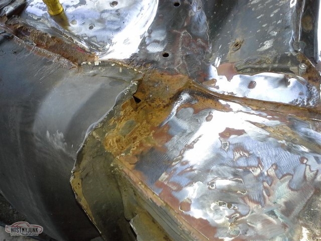
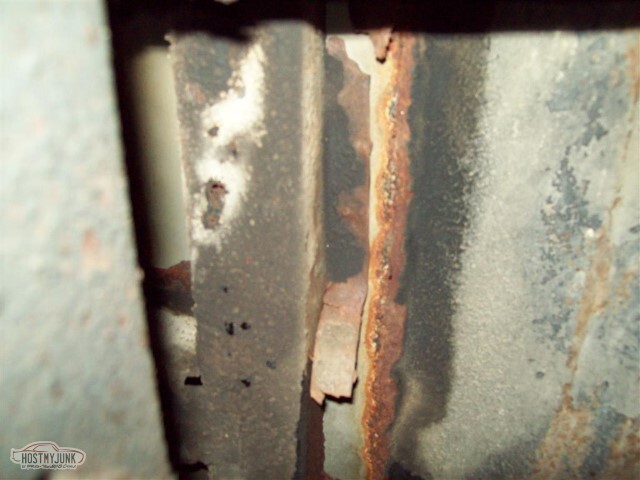
Started by removing the rear window trim. I knew I had at least a little rust in the channel that I'd need to take care of.
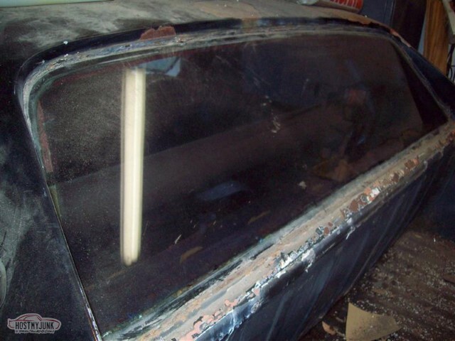
It's hard to see with the flash, but there's a pinhole of light in the top right corner. That's The Rust I Knew About.
So I took the window out. There's quite a bit more rust than I expected. I'm guessing it was leaking for a long time, and I never noticed the dampness of the material on the package tray.</td><td>

A little more rust further down.</td>

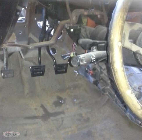
I installed the pedal assembly I had modified for the wider column. I'd bought it used, it was from a 69 (?) Camaro but supposedly was the same as A-body.
Yeah, it isn't. They're similar, but the A-body pedal assembly fits higher on the dash than the F-body assembly. I'd have had to rework what I had to make it fit properly. Then I realized that doing that was silly, I already had a pedal assembly that fit correctly.... but I couldn't find it (part of the driving force behind cleaning was looking for this).
Found it today. It fits better, other than the width issue.

Alternate view of how well it fits (with the single auto brake pedal)

Moved the clutch and brake pedals over (since this was an auto car) but they're binding a little so I'll need to pull it apart and grease things. Still need to adjust the width.
05-15-2021 #35
-ɹoʇɐɹǝpoW-
- Join Date
- Jul 2002
- Location
- Mesquite, TX
- Posts
- 4,901
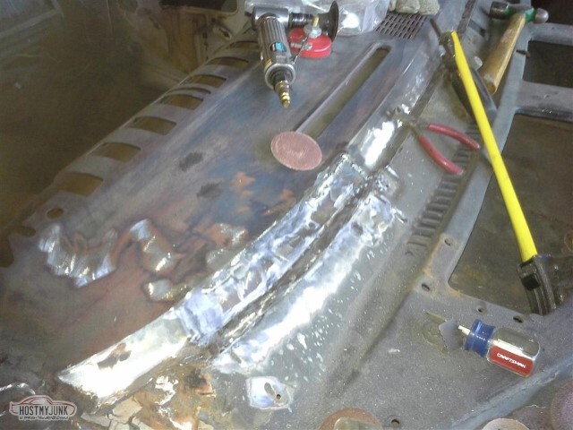
I saw a TV show last month. The host was talking about doing rust repair using a TIG torch and bronze rods.
The gist was that you can fill holes easily since the bronze has such a low melting point compared with the base metal.
I bought two packs of rods - some Silicon Bronze TIG rods (3/32, I think) and some plain bronze brazing rods (3/16 or thicker).
Yeah, that went poorly. All I accomplished doing was making the holes bigger. The TIG rods worked better than the brazing rods (surely no surprise).
Additionally - I got a new cell phone, tried using the camera from that. Won't be doing that again; these pictures kinda suck.
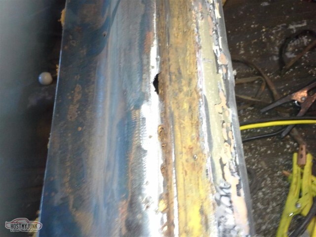
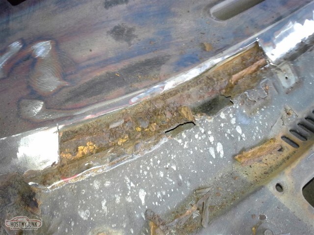
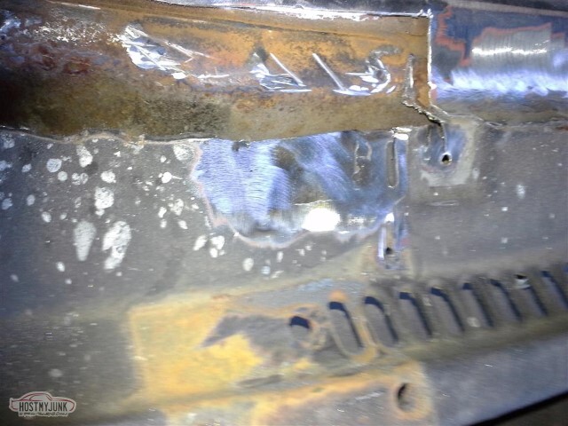
So here's what I started with. The holes are in the package tray on the inside of where the back window goes.
I have not found where the leak was that allowed all the water in, but the seal for the window seemed to be pretty old.
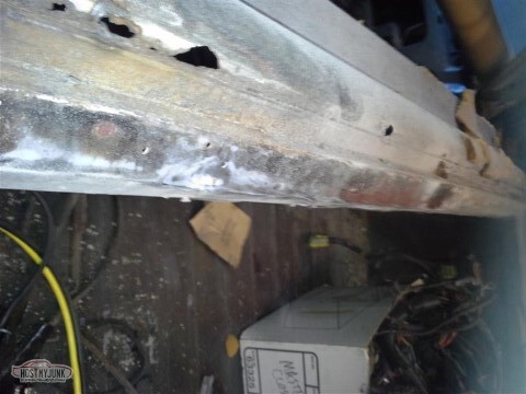
Alternate view of the holes. I successfully filled one, and made several others much larger than they were when I started. I know this is not structural and it'd be safe to fill with something other than new metal - but that's not the way I want to do things.
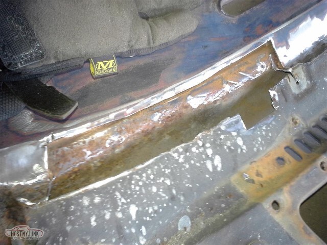
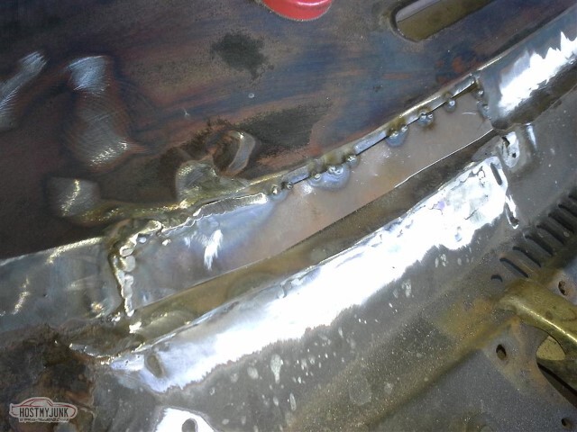
So after trying to clean up the rust-holes, I sanded the flat panel below the window. I knew I had drilled some holes for the front attachment on the tonneau cover, but what I found surprised me: about six separate other sets of holes for tonneau attachment, filled with some sort of
caulking or bondo. All of these will get welded up.
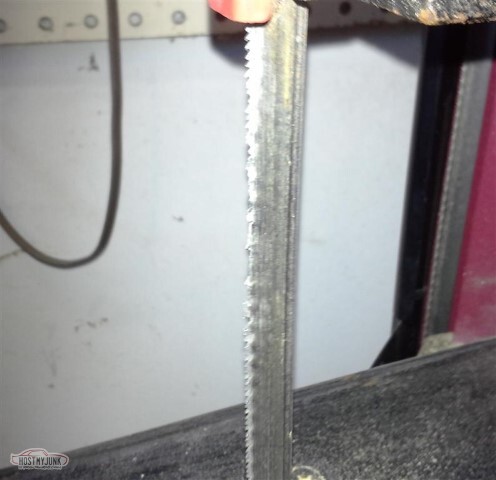
So I figured out why the bandsaw keeps throwing the band (other than being a cheap HF saw): there are several places on the blade where there are no teeth. When it hits one of those areas, the blade stops and comes off the pulleys. I've known I needed a better blade, now it's confirmed. I don't like the way it twists the blade 45 degrees offset for the cutting surface either, perhaps the whole saw needs to be adjusted - I don't need the setup where the saw can be lowered onto a piece of metal.
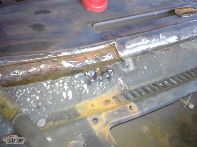
So I cut the mounting points for the pedals (with the band saw) so they'd fit the adjusted column mounts. Got them reassembled, lubed, and mounted as shown here.
So the ATS clutch master bracket mounting holes don't QUITE fit the A-body pedals - which surprises me, but is simple enough to correct.
Of greater importance - I am going to have to rethink the master cylinder, or at least the ABS system -- I cannot reuse the lines that the donor Camaro/TA had as they put the ABS box in the PS pump. I can probably just make new lines but I think that somebody mentioned that an S10 MC has the same piston diameter but has the ports on the driver's side of the MC.
So this is a picture of the sail panel inside. I am assuming that this bracket is what a shoulder belt would attach to - but I've got two threaded holes around what I would think was the belt attachment unthreaded in the middle. Anyone know what bolts here?
Next up, the column-base-trim was wrapped around the steering column to properly locate the shaft at the firewall. Still need to screw everything together - and will have to cut a hole for the clutch pushrod, but this is progress.
And then a reminder occurs: I've got some rust issues on the windshield frame too.
And both cowl sides.
And the driver's side floor.
And my crappy repairs to the bed 10+ years ago.
Really I need to sand down the whole firewall, or at least this side, before mounting things.
So that's where I stand: 1 step forward, 2 steps back. At least it's progress, of a sort.
2021-05-15 edit: I sure say "so" a lot! Also, sorry about the rotated pics - they weren't that direction on the source, and I can't figure out how to get HMJ to rotate them.
05-15-2021 #36
-ɹoʇɐɹǝpoW-
- Join Date
- Jul 2002
- Location
- Mesquite, TX
- Posts
- 4,901
So not that productive of a day. Lots of planning and prep work to do, which is now (to an extent) done.
The lower column brace bracket (whatever you call it) from the stock 69 column does indeed fit correctly for the 2000 Trans Am column I'm putting in. The screws to hold it all together are #12x1" (I had to go buy some). Here the column is mounted, even though I'll have to pull it all back apart when I mount the clutch master. I'm one short on #12 screws, but it probably won't matter as the far-right screw hole will likely not exist in the altered firewall.
Used the drill press to enlarge the bottom two bolt-holes in the AFX clutch master bracket. Now it fits, but needs paint (in general, not from the drill press)
Mounted the booster to the bracket too. Almost looks like progress, but this too will need to come off so I'm not sure why I did it.
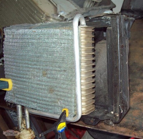
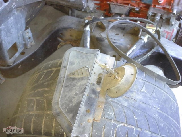
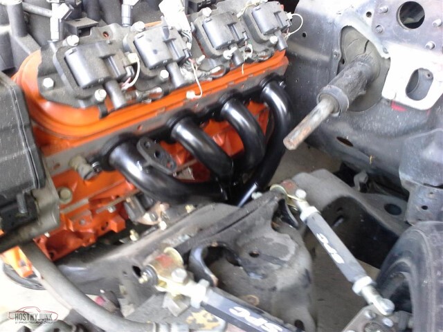
So on the AC box - I don't like the little notch that I put in the firewall, I want to close that back up - but the LSx-era coil is larger than the stock box will fit, so I'll need to adjust the box if I'm going that way. I am assuming that fiberglass works for repairs on these. It better, since I already cut the hole for the lines here.
Note that the pointy bolt on the coil packs is far too close to the box and will need to be replaced with a normal bolt, as well.
So note the body mount thing between where the fan goes and the rest of the box. I know the fan chamber can't grow without ruining airflow, and I also figure that it can't get much bigger near that mount lest it interfere with the fender.. so I'm thinking to slit the whole box at the red line and expand it however much is appropriate for this coil.
Conveniently enough, I have a spare (unmolested) complete AC box so if this doesn't work out, I can just swap that one out.
I also need to repair this flappy-thing. The hinge has seen better days, and the vacuum canister bracket is broken. Figure I can make a linkage, not sure yet how to fix the hinge.
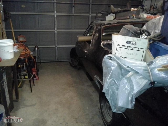
And then I spent hours cleaning the work area. Not that you can really tell, but there was a lot of stuff on the left side of the picture that has been put away now (a couple of tool boxes, a full size drill press, a lot of garbage). This should make future work easier.
The tube sticking out of the window contains the window chrome - it's a heavy cardboard tube from a roll of linoleum so should protect everything well. I need to seal the ends and put it up in the attic.
So I spent a little bit of money: I ordered the headers (Hedman 68534). They're uncoated LS1 headers for a 2000 Camaro/TA, and they have the EGR/AIR ports so at the very least I'll have that to rework. With those, and finishing the firewall rust repair/paint, I'll be ready to put the front clip back on (which doesn't mean it'd run - still need electric and fuel and cooling and different accessories). Need to finish the frame welding too.
Additionally, I found, bought, and installed the band saw blade I needed so hopefully I can now cut metal without having to put the blade back on the pulleys every half inch.
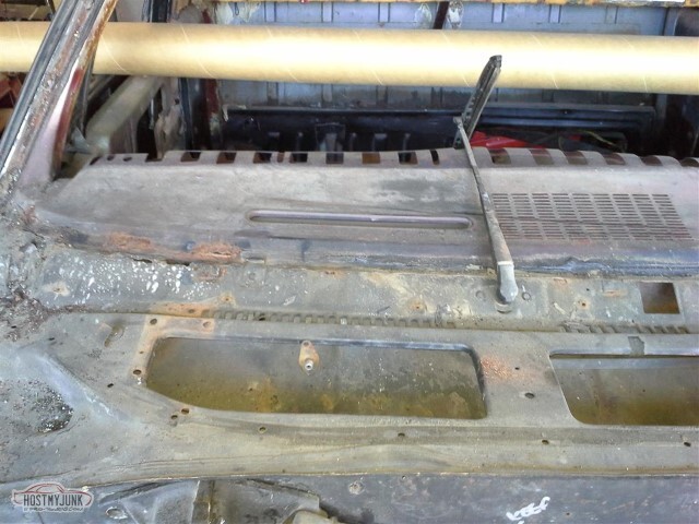
I am not really sure how the package tray repair is going to go. I *know* that it doesn't have to be perfect; that I can get it close and cover the panel with vinyl or something, but that doesn't seem "right" and I'm thinking that I want to do the package tray the same as the dash - eggshell black paint. We'll see how it goes.
05-15-2021 #37
-ɹoʇɐɹǝpoW-
- Join Date
- Jul 2002
- Location
- Mesquite, TX
- Posts
- 4,901
Started by removing the windshield (not that difficult,I cut the glue away last year and it's just been sitting there). Need to clean the dash-top for repainting (several coats and the black is giving way to the previous reds and blues) and of course there's the rust I've shown a few times.
I'm guessing that not only was it sufficient to glue the window in, but also somebody tried to ensure a good seal with silicone caulking (since there's both black and clear glue here). Alternately, the window was reglued by someone who didn't clean out the old glue first.
Lots of goop in the upper channel. The middle trim clip was much rustier than the others; I hope this doesn't foreshadow something bad.
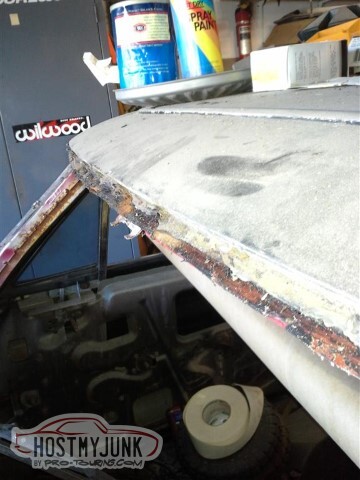
So yeah, this pic came out extraordinarily blurry. What you would be seeing if it could be made out is some rust damage to the lower lip of the windshield frame on the driver's side. It's not rusted through so I am not yet sure how I want to handle this.
I've had a pile of the Roloc disks for a while and hadn't ever used them. I think they work pretty well. Started on the driver's side frame and got a bit carried away. I'll need to prime all this anyway. The paint here on the cowl appears to have been the original and wasn't holding up well anyway - using the air nozzle on it was flaking chunks off. White primer, or at least I think that was the primer.
Pulled out some of the seam sealer for the cowl side that I'll need to replace. New shopping list item: more seam sealer (I bought the new cowl panels back in 2008! I may be a slacker, but I plan ahead)
2021-05-11 edit: (this entry is from 2013)
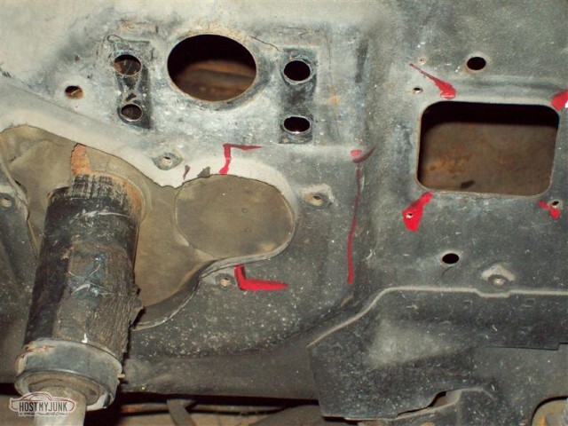
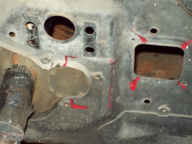
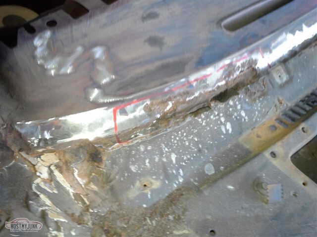
So I figure I need to figure out what I'm doing. The red marks indicate where I figure the cuts should be - where there'd be enough good metal to weld to. This is scary though, there's a couple of different curves and some bends and I don't have a good brake or (any) roller.
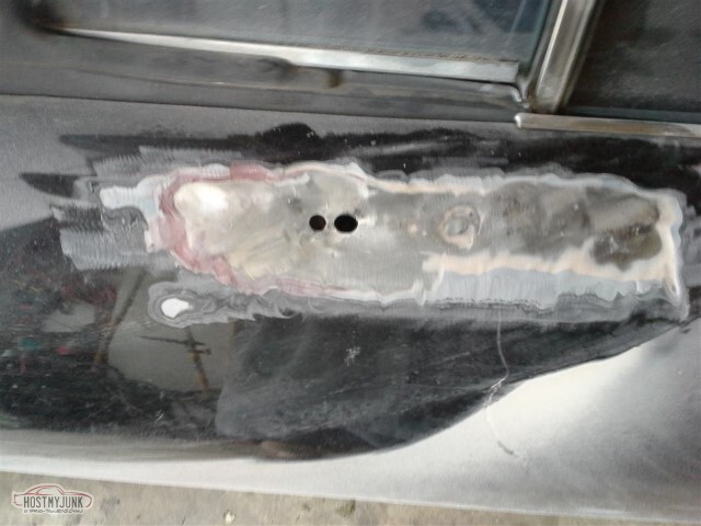
So first I go try to do something smaller. I'd drilled holes in the door to mount the crappy side mirror, and now they're just holes.. and I can see a bubble where the hole from the previous mirror was just bondo'd up.. so let's weld them closed.
Thats's a lot of bondo on the door.
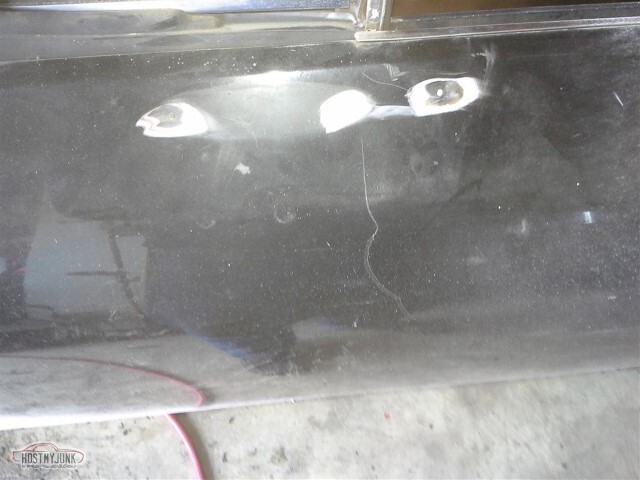
And then I expand the area where I've checked for holes, found and welded up several others, and then I find this monstrous hole, again just filled with bondo.
I expect to find things done incorrectly, but I don't like it when I'm not the one responsible.
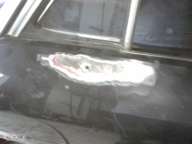
Not sure how well it comes through... but not only is there a hole there, but the door skin is pushed in 3/16" or so.
Not sure yet how I want to correct this.
Hoping the extra filler is only in this area.
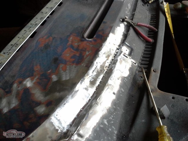
Okay, enough playing. Time to get to work on this windshield channel. Start by cutting on the first set of lines, to get the back of the channel.
Then the second and third sets of lines. Will use three separate pieces of metal to correct this. I don't have a brake or a slip-roll, but I do have a very nice throatless shear so I can make patches.
I do not, however, have particular skill at welding. Here the first piece has been tacked in place.
And then it's been welded around the perimeter. This was the easy one.
So I forgot to take any pictures of the second piece going in, or the test fits of either of these pieces, or the painting of the backsides. Second piece went in perfectly. Third piece, not so much.
I've run out of coarse/medium Roloc disks, and the fine don't really do well on smoothing welds so I think I'm done for the day.
It looks better in the picture than it does in real life. I seem to have forgotten two things:
1) Hot metal warps.
2) This is an important piece. Don't use a "good enough" mentality.
I've got a ~1/8" low spot in the top of the dash here, and the channel-back has about a 1/4" low spot. I am not yet sure how I want to correct these, and I still need to clean up and finish the welds. I've had a stud-welder on the tool list for a while, perhaps this is the justification I've been needing. That would likely also help with the door mirror dent thing.
I think the cowl sides are next. Either that or the closing up of unneeded holes, but to do that, I'll have to put the tunnel back in place, and before I can do that, I need to do the body mounts so I have the final clearance... so probably cowl sides.
05-15-2021 #38
-ɹoʇɐɹǝpoW-
- Join Date
- Jul 2002
- Location
- Mesquite, TX
- Posts
- 4,901
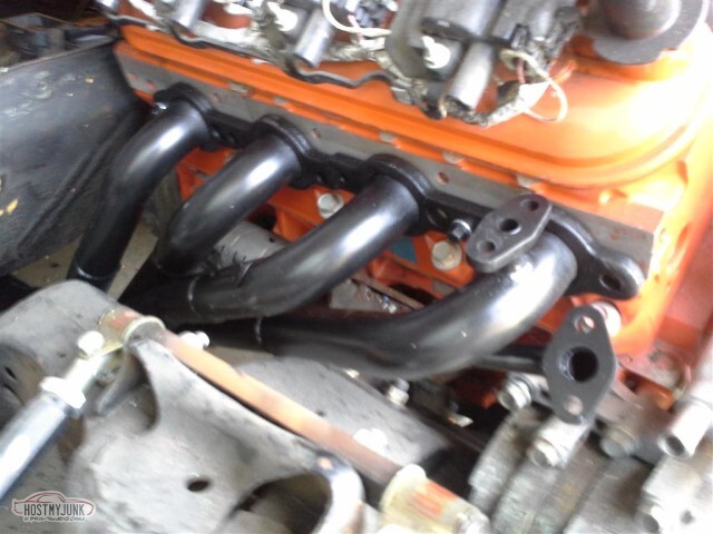
So the headers came in, after the email from Jegs that said they wouldn't ship until the end of the month.
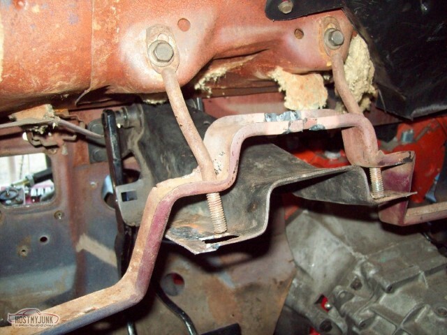
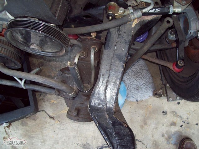
I bought Hedman "hedders", PN 68534 - they're supposed to be direct-fit headers for 98-02 Camaro with the LS1; bought them with the expectation that I'd have to do some substantial modification to get them to fit with my homemade engine mounts.
Yeah, that's not really so much the case. Especially on the driver's side, there's actually very little that needs to be changed.
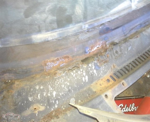
There's one spot where they rub on the crossmember.
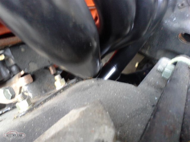
Passenger side is very similar.
I figure I can dent the pipe a little here to clear.
Alternate view.
I've got to dent the pipes, I need to strip these and paint with proper header paint, and I will need to cut off and weld up the spots for all the emissions stuff that won't be needed here.
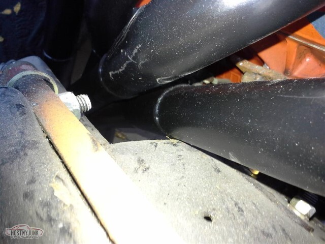
There's also one more interference point, only on the pass side: The flange kicks out enough to hit the frame at its lowest point. I actually figure that will fix itself, but we'll look closer when denting the pipes.
I must admit, I'm pleased with the Hedman quality and completeness - it came with the gaskets, blockoffs for the emissions stuff I'm not using, the collector flanges, and all the bolts needed.
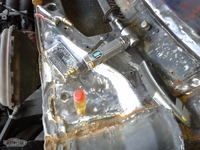
Cut off the studs used for the stud welding and ground down the remainder. There was another hole that was filled with putty.
2021-05-11 edit: I guess I did get the stud welder around this timeframe?
Corrected the low spot in the dash top, too - cut the edge, pried it up, rewelded.
05-15-2021 #39
-ɹoʇɐɹǝpoW-
- Join Date
- Jul 2002
- Location
- Mesquite, TX
- Posts
- 4,901
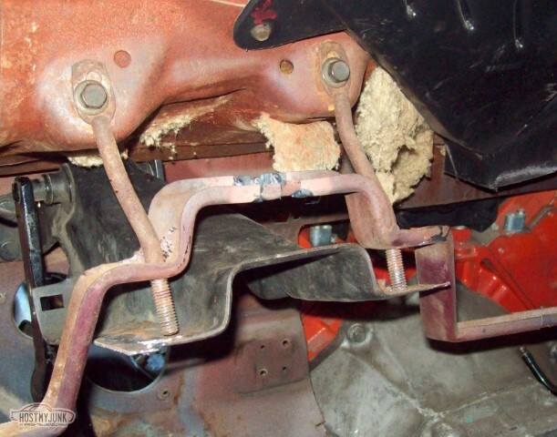
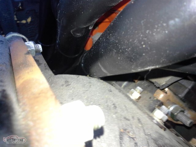
So the headers fit pretty good, except for the things that don't.
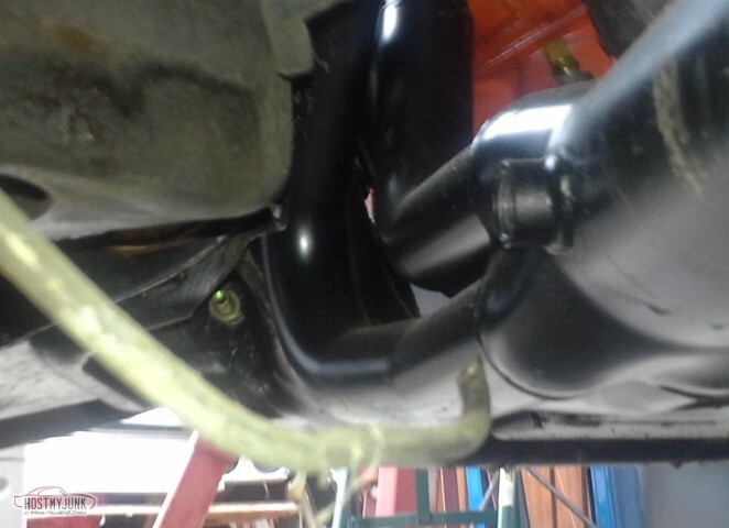
This being one of them - the driver's side tube is too close to the frame to actually put an oxygen sensor in there. Need to either move the bung to the other side, or move it further back.
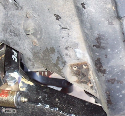
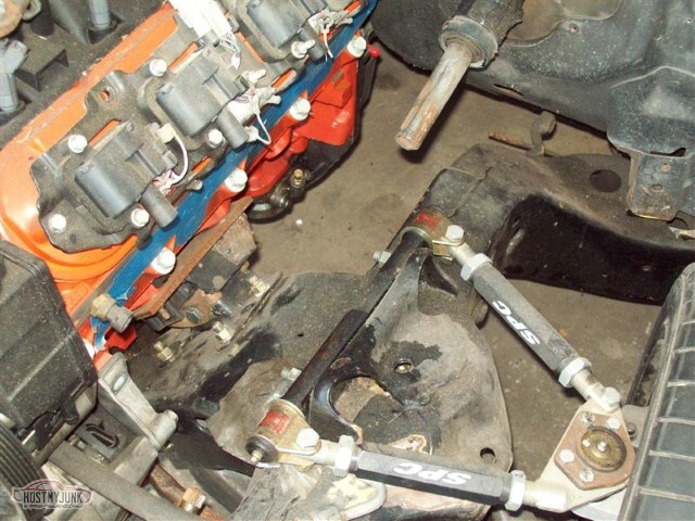
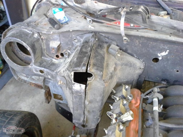
On the pass side, here's where the header arcs out enough to clip the frame just above the LCA mount.
05-15-2021 #40
-ɹoʇɐɹǝpoW-
- Join Date
- Jul 2002
- Location
- Mesquite, TX
- Posts
- 4,901
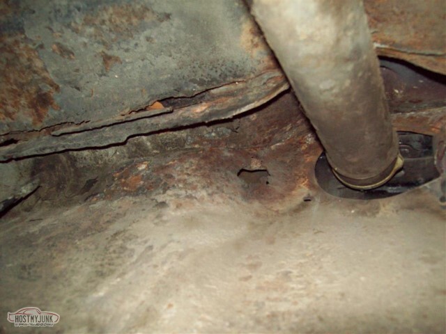
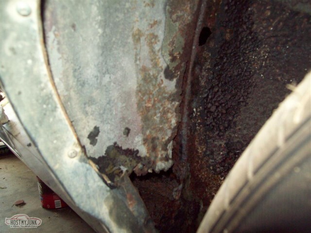
Got most of the body mount bolts out (all but the far back on the driver's side, front on the pass), but the more I look around the more rust I find. I'm almost to the point where I'm ready to start looking for a 69 Chevelle to move all these parts over to, it's rather disenheartening to find yet more rust.
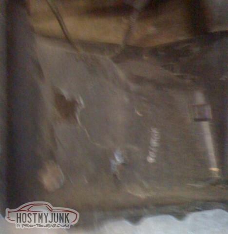
These glowing spots are holes on the pass floorboard behind where the seat goes. There are many; more than what the picture would indicate. New floorboard or a heavy-duty patch job.
No idea how this happens - inner part of the bed, next to the fuel filler. Guess this is more patching (once the tank is out). You can also see some rust damage at the edge of the bed. That's going to be a pain to repair.
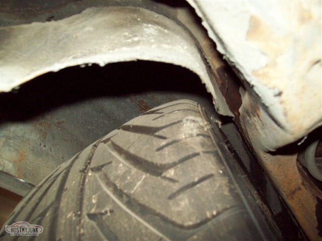
Odd that the inner fender is that far from the frame there. Simple enough to correct once the wheels are off, should free up some space for a little wider tire.
Here's where I repaired a hole in the bed years ago. Looks like there was some rust to the bed reinforcement too.
Additionally, the rear mount on this side appears to be spinning in its cage; once the tank is out I'll need to cut an opening to fix that. Looks like tank/axle removal is coming sooner than I expected.
Two separate rust holes in the driver's rear fenderwell (knew about these already, but that's more I'll need to handle when the axle is out).
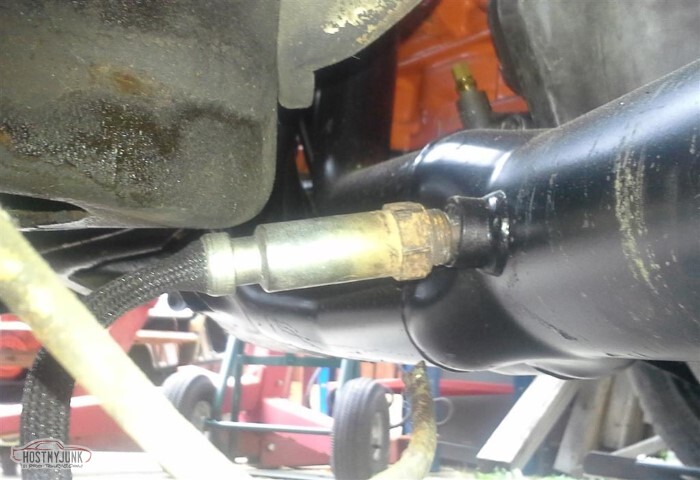
Once I replace the accessories, I'll need to get new hoses... and the steering box needs to be cleaned up. For my future reference, the hose closer to the driver's wheel is the low pressure hose.
Driver's door is completely torn down now (or at least as far as I'm taking it). Need new window fuzzies and vent window weatherstrip; better to replace the drip rail and window moldings too, or at least polish these; not sure that mine are straight enough anymore though.
On a happy note, it looks like one of the driveshafts is an appropriate length. I can't put it in as the floor brace is too low at that point but nice to know that once it's raised I'll have one that fits (once I replace ujoints and the diff yoke).
Bought the bolts to do the new body mounts and I already had some new poly bushings.
Still need to tear the front end back apart and clean up/reinforce the frame and do the firewall cleanup (and AC box and all this rust repair and correct the headers and this and that and the other thing)

 Reply With Quote


