Results 621 to 640 of 786
Thread: 1970 GTO Version 3.0
-
01-29-2023 #621

 -Moderator/Sponsor-
- Join Date
- Apr 2001
- Location
- The City of Fountains
- Posts
- 15,975

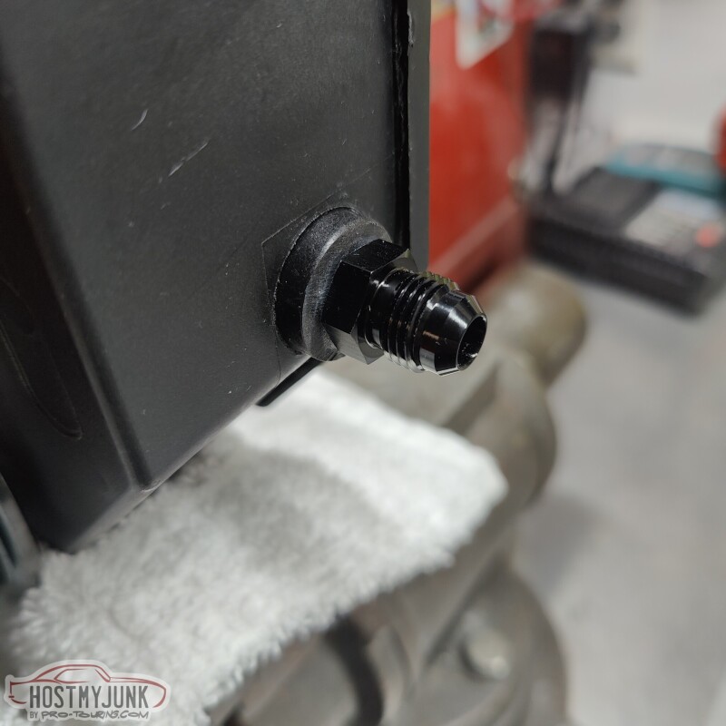
A quick trip to Star Performance produced the 1/8" NPT to AN-6 Male fitting, and the power steering return is now sorted.
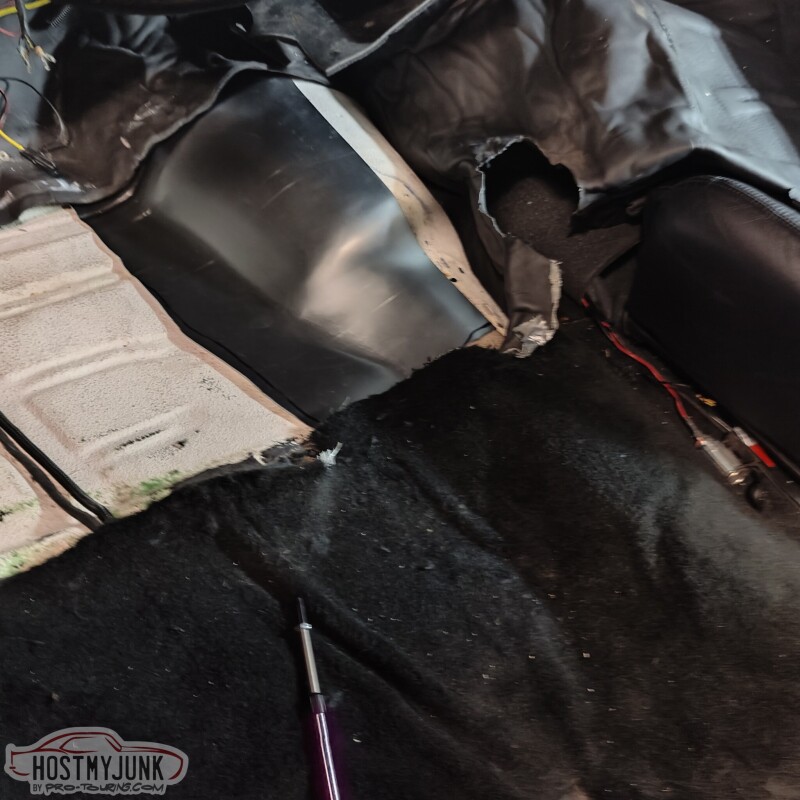
The next project to tackle was this hole in the side of the transmission tunnel.
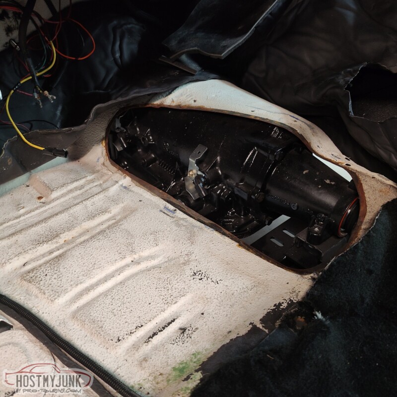
The hole used to have a cover that had a shifter hump in it to clear the shifter and linkage for the Richmond 6 speed that used to be in the car. With that transmission gone and the 4L80e in its place, a new cover needed to be made.
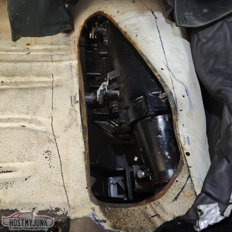
Here you can see how close the transmission is to the trans tunnel. My body bushings are 20 years old. They are not cracked, but I am sure they have settled some, which is contributing to the lack of clearance.
A quick Google search showed that partial floor pan patch panels were readily available. I called The Parts Place and they had one in stock and had it at my door in two days. You can see that part of the panel includes the needed piece to start making a new cover for the tunnel.
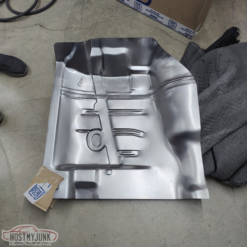
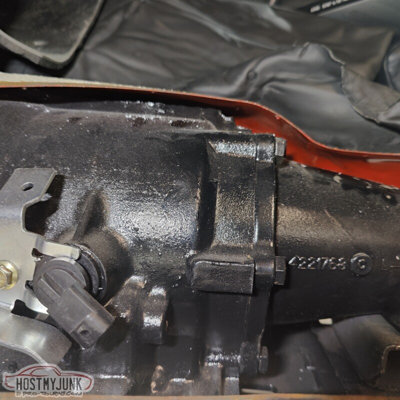
I trimmed it big to start...
Then trimmed it to the final shape...
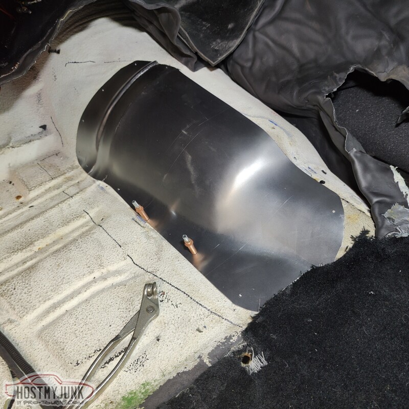
and started to drill the necessary mounting holes.
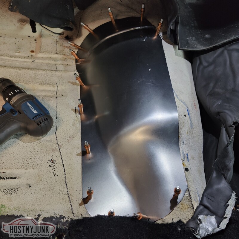
Turned out pretty good in the end, without having to do any custom metal shaping, which I don't have the skills to do anyway....
Andrew1970 GTO Version 3.0
1967 Cougar build
GM High-Tech Performance feature
My YouTube Channel Please Subscribe!
Instagram @projectgattago
Dr. EFI
I deliver what EFI promises.
Remote Holley EFI tuning.
Please get in touch if I can be of service.
"You were the gun, your voice was the trigger, your bravery was the barrel, your eyes were the bullets." ~ Her
-
01-29-2023 #622
 Registered User
- Join Date
- Nov 2006
- Location
- Ma.
- Posts
- 5,567
The floor came out nice, is it going to be removable? That wrap for the up/down pipes looks like a nice setup.
Wayne
Car FINALLY home !!!!!! lol
Project FNQUIK https://www.pro-touring.com/showthre...ghlight=FNQUIK
-
01-29-2023 #623
-Moderator/Sponsor-
- Join Date
- Apr 2001
- Location
- The City of Fountains
- Posts
- 15,975
Yes, it will be removable, like the old one was. Originally Posted by Motown 454

Andrew1970 GTO Version 3.0
1967 Cougar build
GM High-Tech Performance feature
My YouTube Channel Please Subscribe!
Instagram @projectgattago
Dr. EFI
I deliver what EFI promises.
Remote Holley EFI tuning.
Please get in touch if I can be of service.
"You were the gun, your voice was the trigger, your bravery was the barrel, your eyes were the bullets." ~ Her
-
02-01-2023 #624
-Moderator/Sponsor-
- Join Date
- Apr 2001
- Location
- The City of Fountains
- Posts
- 15,975
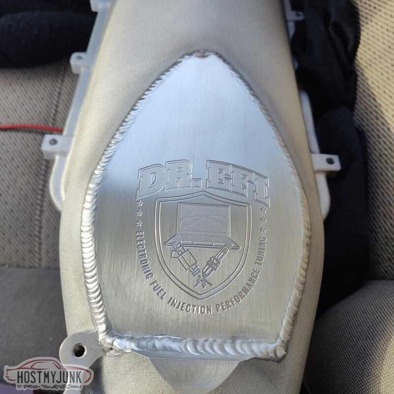
I took my intake to Hot Rod Express, where they welded the engraved manifold cover plate to the Holley intake lid.
Today was the day that I wanted to get the heat exchanger mounted and start thinking about running the plumbing (so much plumbing in this car!!!) the A2W intercooler system. When I originally asked Vic to mount the heat exchanger to the radiator, I really had no idea how things would be plumbed. I had him mount the heat exchanger with the inlet and outlet (dual pass) on the driver's side. Clearly this is not going to work.
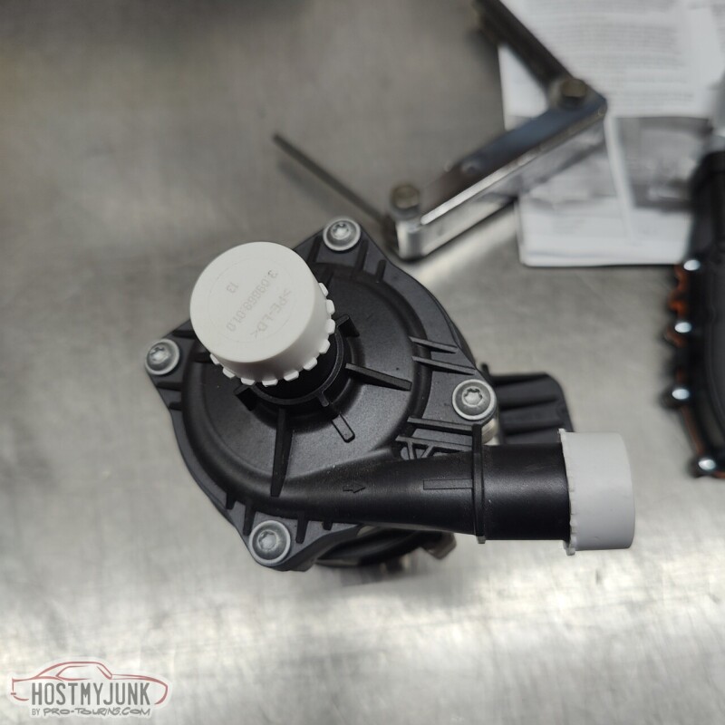
With the intercooler, fill tank, and circulation pump in place, it was clear that the best option would be to have the input and outlet on the passenger side. Before digging into that further I wanted to make sure that the circulation pump fittings would be oriented in the correct direction. I emailed Tobias at Tecomotive and he quickly responded that the pump inlet and outlet cover can be clocked in any of the 4 positions relative to the pump body.
I unscrewed the top and it sure doesn't look very fancy in here, but this pump is supposed to move A LOT of water.
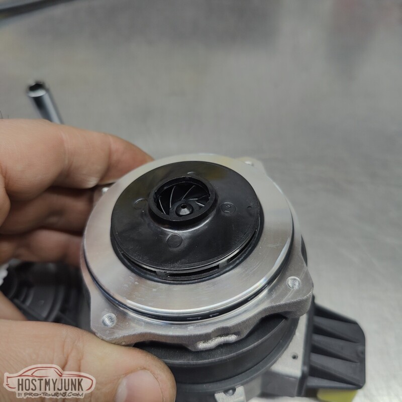
Not much to see here....
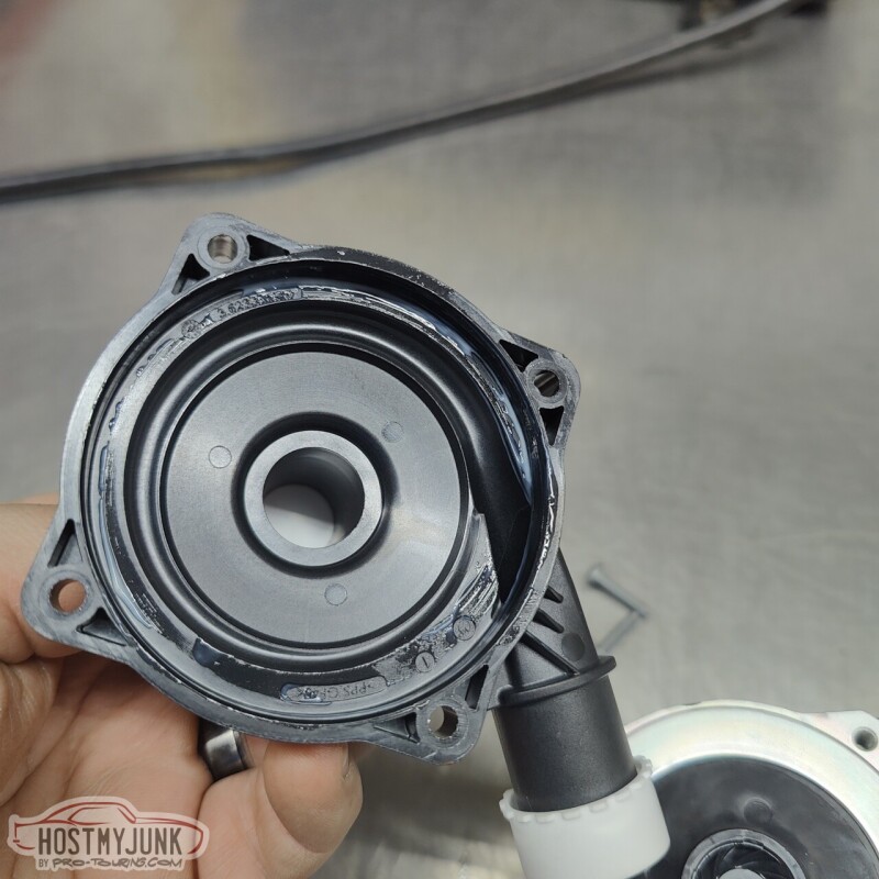
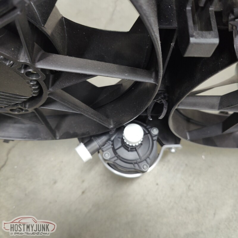
I positioned the pump body in such a way that the connector was close to the fan shroud so that the wires for the pump could be routed along the bottom of the shroud.
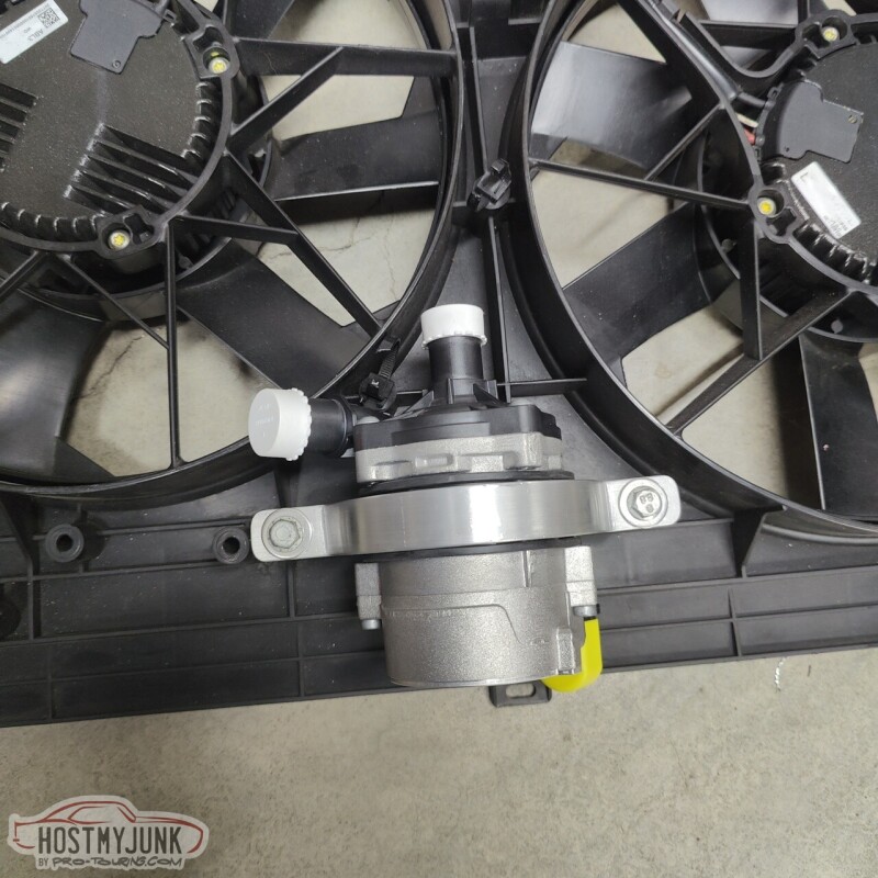
I clocked the top so the outlet would face the passenger side (the top is the inlet).
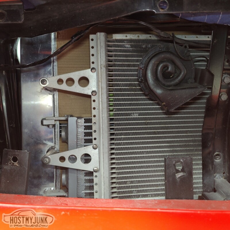
I also pulled both grill inserts so it would be easier to work in front of the radiator. As I was going along, I always had to make sure that I could get to everything without having to pull the grills, because once the radiator is installed, there is no way to access the grill hardware.
Here you can see that the heat exchanger was flipped (the drain is now at the top and can't be used). We couldn't rotate the heat exchanger because that would have required a complete reworking of the mounts and I did not want to do all that. I can live without a drain.
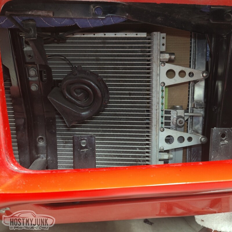
There is a lot more room on the passenger side for plumbing because the radiator core is slightly offset to the driver's side (note the larger tank on the passenger side).
With that orientation locked in, we moved to the bench where some minor fiddling had to be done to make the mounts work.
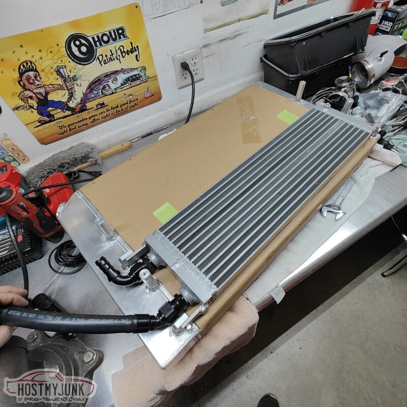
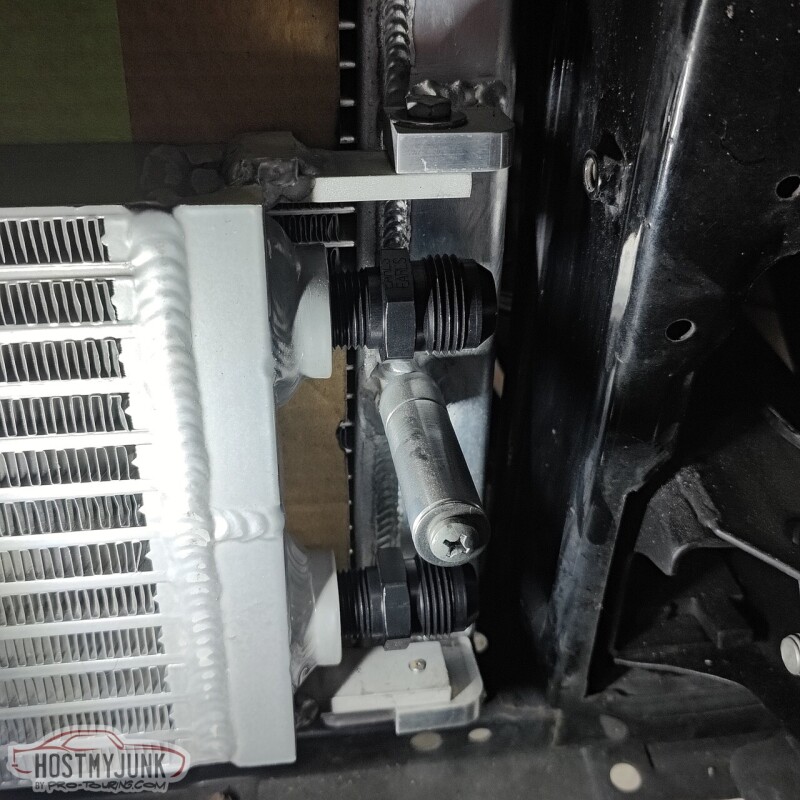
Both the inlet and outlet hoses fit pretty well using 90 degree fittings. With the fans removed and the radiator top tilted back, there is enough room to access these fittings from the top.
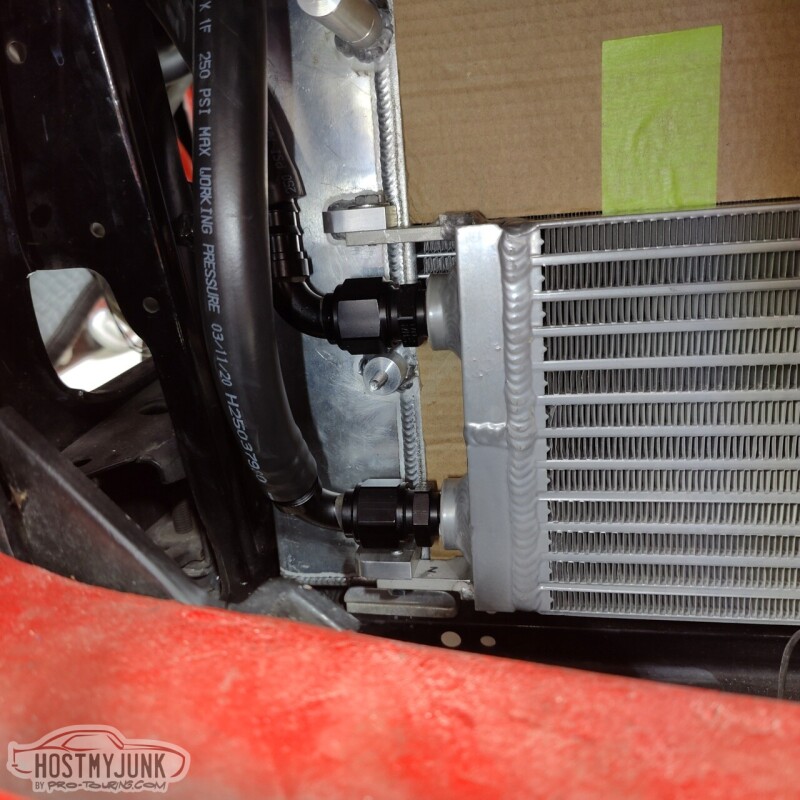
I also trimmed the core support slightly so that the hoses can pass in front of the radiator. You can also see the Low Doller Motorsports temperature/pressure combo sensor in the cooling system.
I still have to finalize the exact hose routing, but this is pretty good progress.
Andrew1970 GTO Version 3.0
1967 Cougar build
GM High-Tech Performance feature
My YouTube Channel Please Subscribe!
Instagram @projectgattago
Dr. EFI
I deliver what EFI promises.
Remote Holley EFI tuning.
Please get in touch if I can be of service.
"You were the gun, your voice was the trigger, your bravery was the barrel, your eyes were the bullets." ~ Her
-
02-02-2023 #625
 Registered User
- Join Date
- Sep 2009
- Posts
- 2,707
Looking great Andrew! That's nice that you were able to just flip the HX and it all still lined up. I'd actually argue that it's more important to have the drain fitting the way that you have it now to help purge air out of the system. It took me quite a while to finally get all of the air purged out of my system.
1955 Nomad project LC9, 4L80e, C5 brakes, Vision wheels
1968 Camaro 6.2 w/ LSA, TR6060-Magnum hybrid and etc SOLD
1976 T/A LS1 6 Speed, and etc. SOLD
Follow me on Instagram: ryeguy2006a
-
02-02-2023 #626
-Moderator/Sponsor-
- Join Date
- Apr 2001
- Location
- The City of Fountains
- Posts
- 15,975
Thanks Ryan and great point about the purging of air! I haven't even considered that. I actually have some LS9 bleeders and I'll see about installing one in the drain. Originally Posted by ryeguy2006a
Andrew1970 GTO Version 3.0
1967 Cougar build
GM High-Tech Performance feature
My YouTube Channel Please Subscribe!
Instagram @projectgattago
Dr. EFI
I deliver what EFI promises.
Remote Holley EFI tuning.
Please get in touch if I can be of service.
"You were the gun, your voice was the trigger, your bravery was the barrel, your eyes were the bullets." ~ Her
-
02-03-2023 #627
 Registered User
- Join Date
- Apr 2003
- Location
- Central Valley, CA
- Posts
- 900
FYI, for all the late model GM intercooler stuff GM vacuum fills them. As mentioned it's nearly impossible to get all the air out of the system unless you vacuum fill the system, as there are often spots in the cores that are higher than the plumbing-- so they're going to trap air at the high spots unless you pull a vacuum on the system. On a few of GM's setups the fill points aren't even the highest spots in the system so vacuum filling is a necessity.
1969 Chevelle
Old setup: Procharged/intercooled/EFI 353 SBC, TKO, ATS/SPC/Global West suspension, C6 brakes & hydroboost.
In progress: LS2, 3.0 Whipple, T56 Magnum, torque arm & watts link, Wilwood Aero6/4 brakes, Mk60 ABS, vaporworx, floater 9" rear, etc.
-
02-03-2023 #628
-Moderator/Sponsor-
- Join Date
- Apr 2001
- Location
- The City of Fountains
- Posts
- 15,975
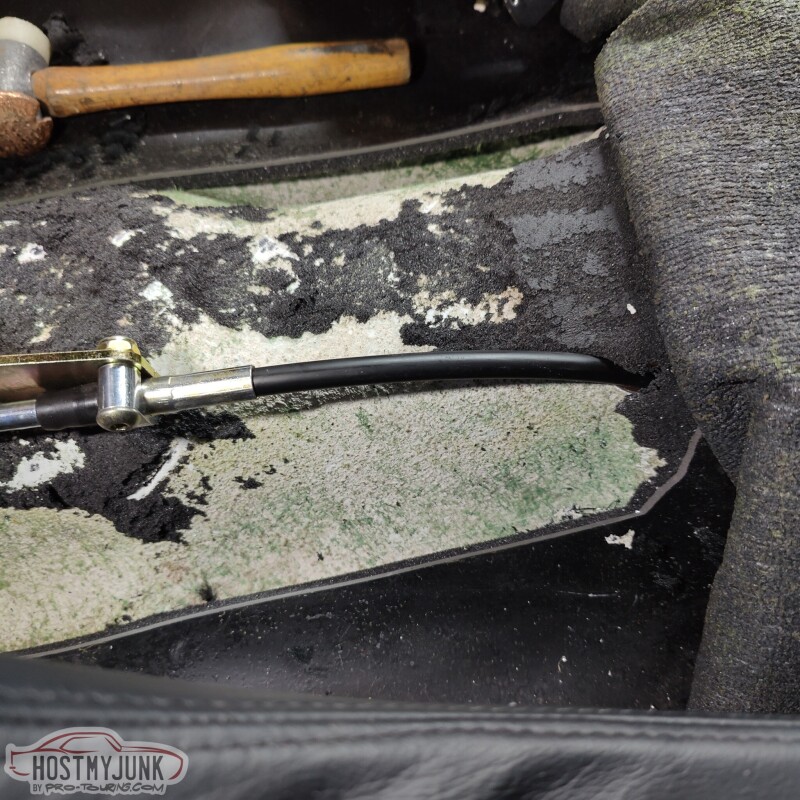
I had mocked up the shifter a while back and it turned out that the 4 foot cable that was included with the Lokar shifter was not going to be long enough. So I ordered a 6 foot cable (which honestly could be 7 feet) from Summit and after it was defrosted in the Texas warehouse, I received it yesterday.
So it was time to put the big boy pants on and poke some holes to mount the shifter. I positioned it in such a way that with the shifter in Drive, I could, very naturally, put my hand on the shift level and slide it to the right and use the forward and backwards tap shift feature.
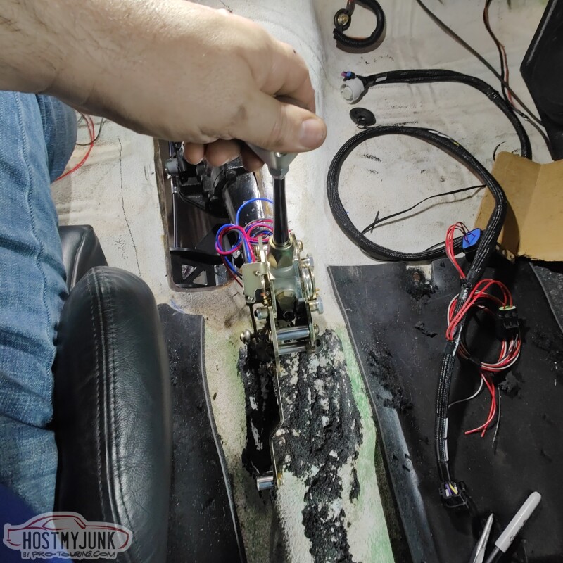
I drilled the first hole and shockingly it lined up perfectly where I intended it to go. I mounted the shifter and marked the other hole.
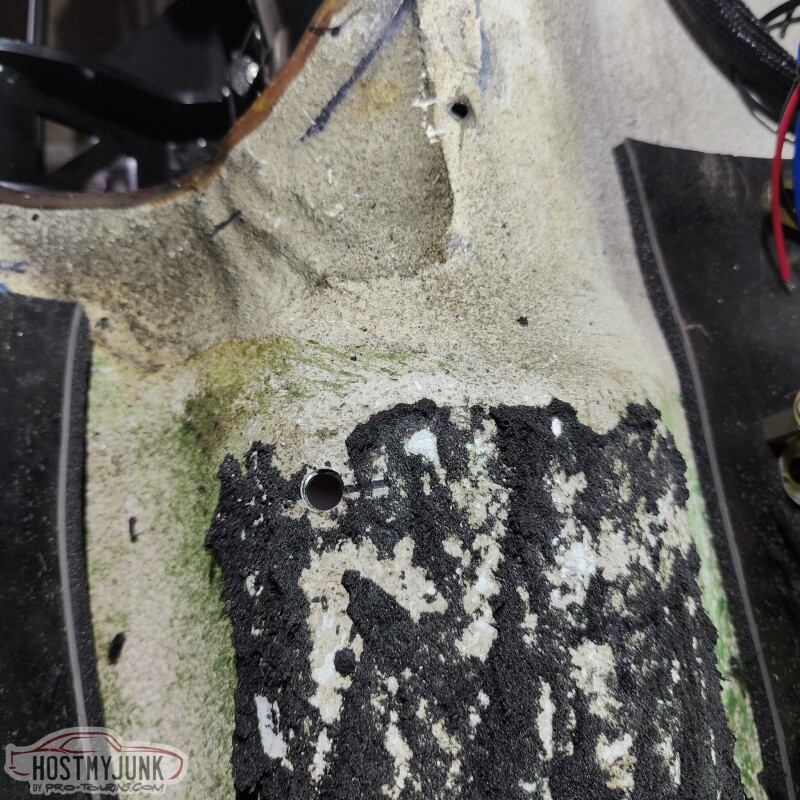
I used nut-serts (riv-nuts) inside the hole and temporarily mounted the shifter.
I did a little more measuring and drilled a hole in the floor for the shifter cable. ICT Billet posted a teaser on their Instagram about their new shift cable pass-through and I have been bugging them about it for weeks. I am hoping it will be available soon so I can use it to seal the hole.
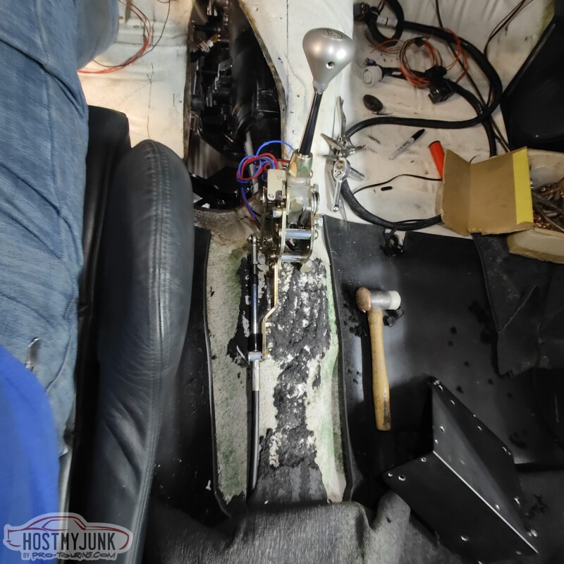
For the front of the shifter, Vic whipped up a simple bracket and we (yes, I welded one side and he the other...thanks you...) welded it to the floor.
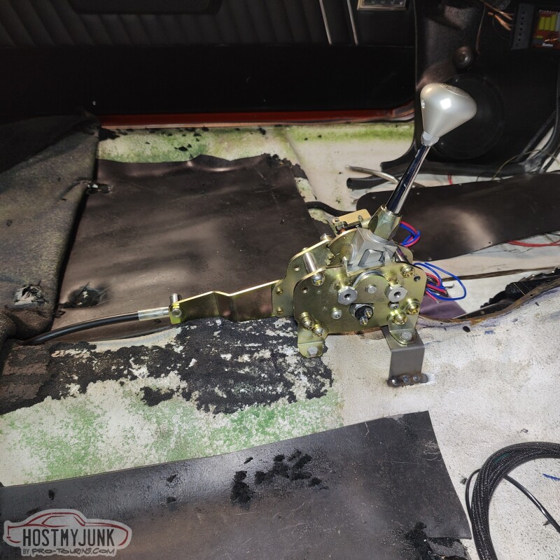
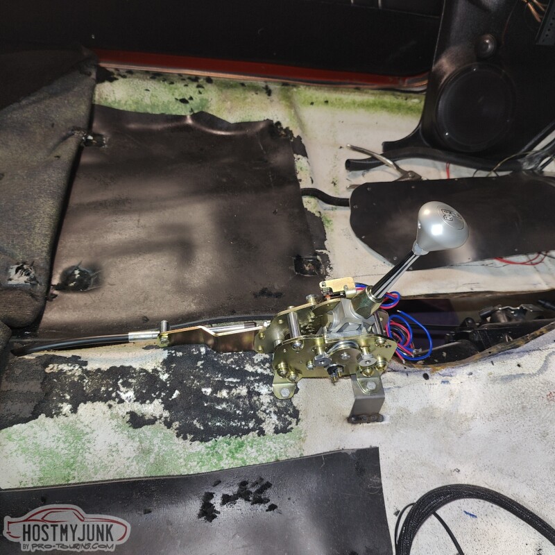
The shifter feels pretty good, but there are some minor adjustments that need to be made still.
Andrew
- - - Updated - - -
Good call on the vacuum bleeding, thank you! I will keep that in mind when the time comes! Originally Posted by Blown353
1970 GTO Version 3.0
1967 Cougar build
GM High-Tech Performance feature
My YouTube Channel Please Subscribe!
Instagram @projectgattago
Dr. EFI
I deliver what EFI promises.
Remote Holley EFI tuning.
Please get in touch if I can be of service.
"You were the gun, your voice was the trigger, your bravery was the barrel, your eyes were the bullets." ~ Her
-
02-03-2023 #629
Registered User
- Join Date
- Apr 2003
- Location
- Central Valley, CA
- Posts
- 900
What's the size of your front mount heat exchanger? It looks pretty undersized to me given the HP that engine is going to make, but I could be wrong.
Reason I'm asking is that it seems far, far smaller than the 3 heat exchangers on my CT4 Blackwing which is only 475hp. It has one center mount heat exchanger that's the full width and probably 3/4 of the full height of the radiator core plus twin side mount heat exchangers that are probably 8 x 10 core size each.
Then again, if you aren't sizing the system to keep the charge air temps reasonable over a full send 30 minute road course abuse session and only sizing it to cool things off after quick WOT blasts from time to time you can get away with a lot smaller heat exchanger size up front.
Datalogging will show if you start to get some heat soak after several back to back WOT passes.1969 Chevelle
Old setup: Procharged/intercooled/EFI 353 SBC, TKO, ATS/SPC/Global West suspension, C6 brakes & hydroboost.
In progress: LS2, 3.0 Whipple, T56 Magnum, torque arm & watts link, Wilwood Aero6/4 brakes, Mk60 ABS, vaporworx, floater 9" rear, etc.
-
02-03-2023 #630
-Moderator/Sponsor-
- Join Date
- Apr 2001
- Location
- The City of Fountains
- Posts
- 15,975
The heat exchanger is 26x7x2. It is a dual pass design, not sure if that makes a difference. As I was installing it, I was thinking that it might be on the small side, but I really don't know. Originally Posted by Blown353
I am definitely not trying to run 30 minute track sessions. This is a street car that will see the drag strip a couple of times per year. I don't have a temp sensor in the heat exchanger, but I can certainly add one to monitor the water temperature of the intercooler system.
I can go with a taller head exchanger, but I can't go wider or thicker. I am open to suggestions...
Andrew1970 GTO Version 3.0
1967 Cougar build
GM High-Tech Performance feature
My YouTube Channel Please Subscribe!
Instagram @projectgattago
Dr. EFI
I deliver what EFI promises.
Remote Holley EFI tuning.
Please get in touch if I can be of service.
"You were the gun, your voice was the trigger, your bravery was the barrel, your eyes were the bullets." ~ Her
-
02-03-2023 #631
Registered User
- Join Date
- Apr 2003
- Location
- Central Valley, CA
- Posts
- 900
I'd suggest calling C&R, they can whip up a worksheet for your target HP level and come up with what size heat exchanger would be needed for adequate cooling under sustained use.
I don't have any access to their heat exchanger core / fin sizes or efficiency and heat transfer data related to their cores, but in the past when I've worked with them they've been very helpful when sizing radiators and intercooler heat exchangers. Once I get further along on my car I'm going to work with them on my heat exchanger. I was previously about 65-70% through my build with twin turbos and a large air to air intercooler, but now that I'm changing to a 3.0 Whipple (I tuned a car last year with an LS3 and a 2.9 Whipple and instant torque anywhere in the RPM range was stupid fun) I have to change over to air to water and I'll need a heat exchanger.
Your heat exchanger looks similar in size to what Magnussen provides with their C5 corvette supercharger kits, I used one of those on a friends 2006 GTO with a Magnussen. It's OK for street driving and occasional WOT blasts but isn't big enough to avoid heatsoak under sustained heavy use, the IATs and heat exchanger water temps started to run away on us on the chassis dyno when I did several back to back pulls. That's why I have a hunch something similar will happen with your setup, although it will probably be just fine for normal street use to keep IATs in check for a few WOT blasts followed by a few minutes of off-boost driving to cool things back down.1969 Chevelle
Old setup: Procharged/intercooled/EFI 353 SBC, TKO, ATS/SPC/Global West suspension, C6 brakes & hydroboost.
In progress: LS2, 3.0 Whipple, T56 Magnum, torque arm & watts link, Wilwood Aero6/4 brakes, Mk60 ABS, vaporworx, floater 9" rear, etc.
-
02-04-2023 #632
-Moderator/Sponsor-
- Join Date
- Apr 2001
- Location
- The City of Fountains
- Posts
- 15,975
What do you think about adding a second, same heat exchanger on top and effectively making it a quad pass design? Originally Posted by Blown353
Andrew1970 GTO Version 3.0
1967 Cougar build
GM High-Tech Performance feature
My YouTube Channel Please Subscribe!
Instagram @projectgattago
Dr. EFI
I deliver what EFI promises.
Remote Holley EFI tuning.
Please get in touch if I can be of service.
"You were the gun, your voice was the trigger, your bravery was the barrel, your eyes were the bullets." ~ Her
-
02-05-2023 #633
-Moderator/Sponsor-
- Join Date
- Apr 2001
- Location
- The City of Fountains
- Posts
- 15,975
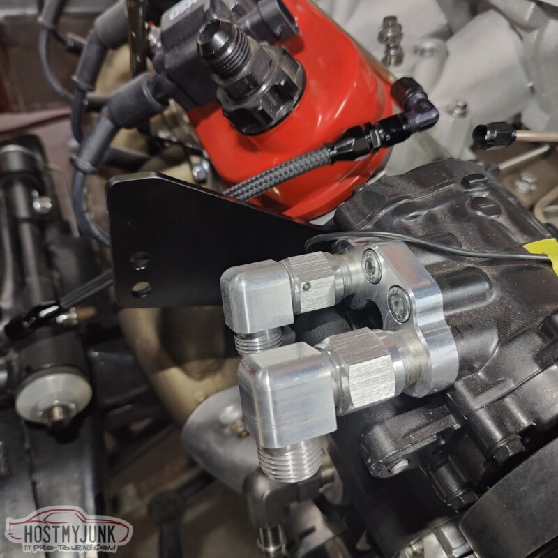
My friend Blake designed and 3D priced a cover the the boost solenoids.
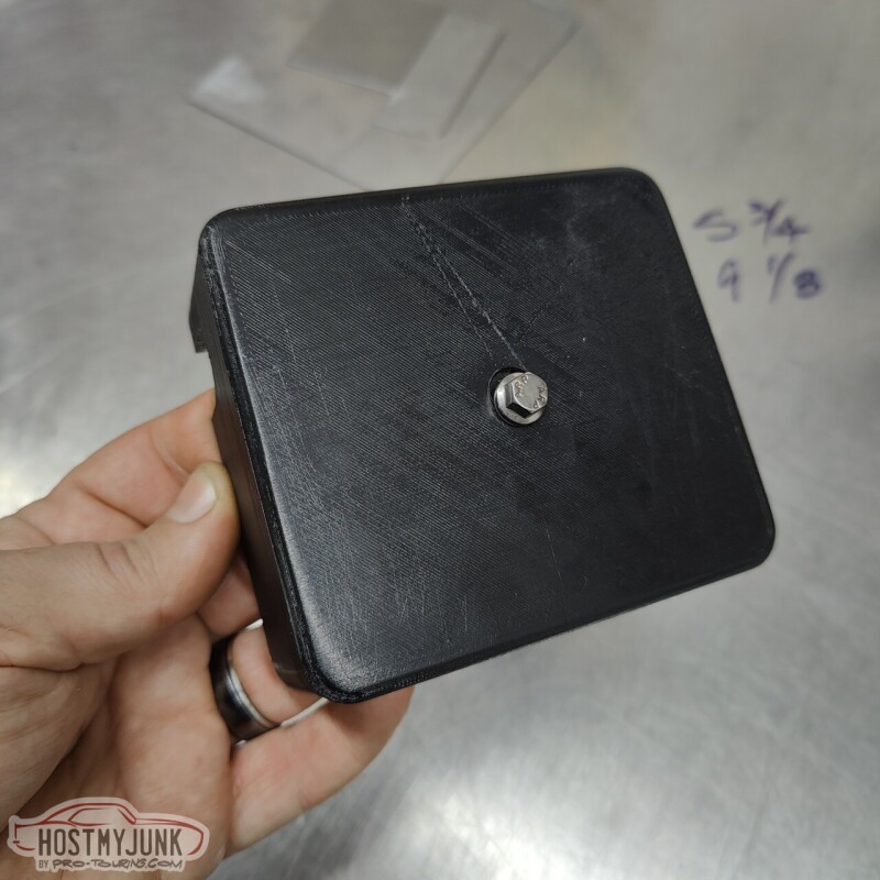
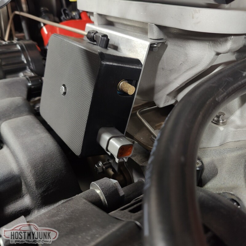
He included a cut-out on the side so that I can mount a Deutsch 4 connector bulkhead fitting, instead of the two connectors that were on the solenoids before.
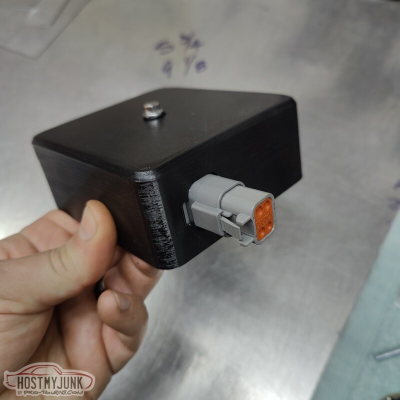
Both Vic and I liked the raw 3D printed look of the sides, but the top was not as pretty. So Vic applied some vinyl to the top.
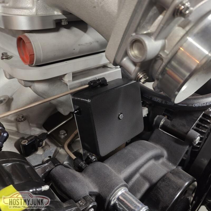
The mounting plate itself is pretty thin, so in order to tap a hole for the hold down bolt, I drilled a small hole and used a punch to gradually enlarge the hole. This folds the soft aluminum out and gives more material to tap, making it as good as a captive nut.
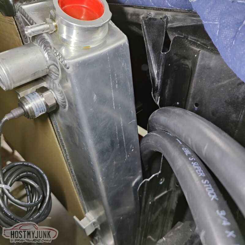
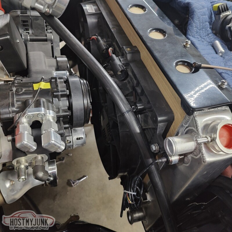
I also made the hose that gos from the fill tank to the top of the heat exchanger.
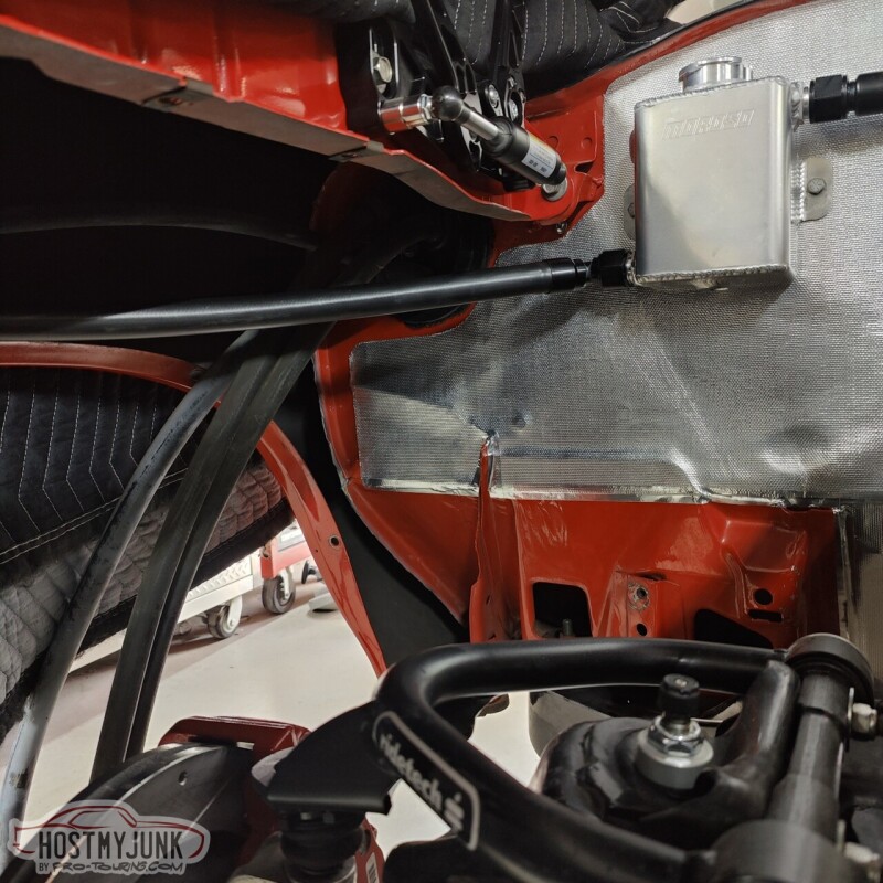
Hear are the two heat exchanger lines where they slip between the core support and the radiator.
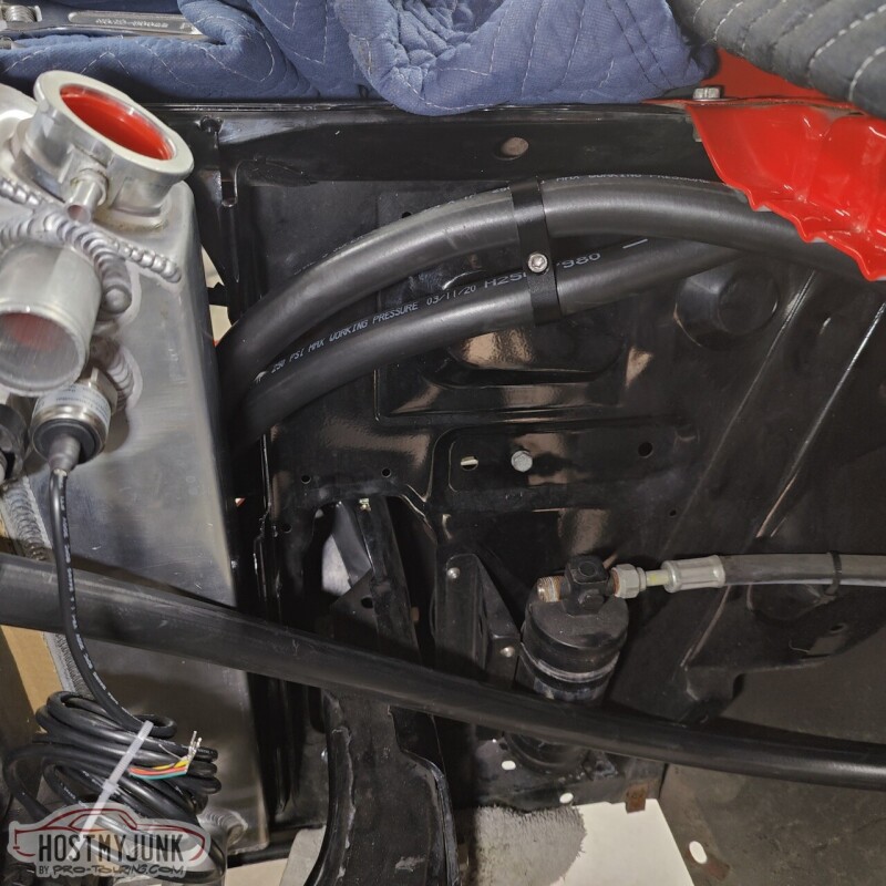
The hose from the bottom of the heat exchanger loops towards the fender, then comes over the fan, and then down into the top of the pump.
I also took the turbo off so that I could rattle can the turbo support bracket.
Andrew1970 GTO Version 3.0
1967 Cougar build
GM High-Tech Performance feature
My YouTube Channel Please Subscribe!
Instagram @projectgattago
Dr. EFI
I deliver what EFI promises.
Remote Holley EFI tuning.
Please get in touch if I can be of service.
"You were the gun, your voice was the trigger, your bravery was the barrel, your eyes were the bullets." ~ Her
-
02-06-2023 #634
 Registered User
- Join Date
- Feb 2013
- Posts
- 1,413
Looks great, Andrew! Good work.
-
02-06-2023 #635
-Moderator/Sponsor-
- Join Date
- Apr 2001
- Location
- The City of Fountains
- Posts
- 15,975
Thanks Josh!
Andrew1970 GTO Version 3.0
1967 Cougar build
GM High-Tech Performance feature
My YouTube Channel Please Subscribe!
Instagram @projectgattago
Dr. EFI
I deliver what EFI promises.
Remote Holley EFI tuning.
Please get in touch if I can be of service.
"You were the gun, your voice was the trigger, your bravery was the barrel, your eyes were the bullets." ~ Her
-
02-07-2023 #636
Registered User
- Join Date
- Apr 2003
- Location
- Central Valley, CA
- Posts
- 900
Youve got me digging way back into my memories of thermodynamics and fluid dynamics, but I think youd be better served running the 2 dual pass heat exchangers in parallel rather than in series as a single 4 pass heat exchanger going from memory here but IIRC as the delta T gets closer between the water and the air going through the core, its going to be less efficient in terms of removing heat from the water. You want a larger delta T between the water and air to carry more of the heat away, but not excessively large. Originally Posted by andrewb70
Running the 2 heat exchangers in series as a single 4 pass heat exchanger might end up with a very low delta T between the water and air once the water gets to the 3rd and 4th pass, and those extra passes wont do much for transferring heat from the water to the air at that point and the water having to flow through all that extra core length with no extra cross sectional tube area when the heat exchangers are in series will increase the backpressure your pump has to push against, and more backpressure reduces the overall water flow rate of the pump and thus decreases the overall heat transfer rate that the system is capable of.
2 double pass cores in parallel should be more efficient at shedding heat since each core will have a larger delta T between the water and air, and with the cores being in parallel the cores should have less backpressure than a 4 pass series arrangement since the pump will see the 2 parallel heat exchangers as a larger double pass heat exchanger with tubes that are the same length as a single heat exchanger but with double the cross sectional tube area available for flow, so your overall backpressure should be lower putting the pump into a more favorable spot on its flow vs backpressure curve so the overall water flow rate will be higher, and a higher water flow rate will also help with more rapid transfer and removal of heat.
Again, this is all going off rather rusty memories from various classes many years ago. Id have to dig back into books and equations to see if my gut feel is correct, lol1969 Chevelle
Old setup: Procharged/intercooled/EFI 353 SBC, TKO, ATS/SPC/Global West suspension, C6 brakes & hydroboost.
In progress: LS2, 3.0 Whipple, T56 Magnum, torque arm & watts link, Wilwood Aero6/4 brakes, Mk60 ABS, vaporworx, floater 9" rear, etc.
-
02-08-2023 #637
Registered User
- Join Date
- Sep 2009
- Posts
- 2,707
That solenoid cover you had 3D printed is really cool Andrew. Not sure if you want to or not, but I'll bet you would could sell those.
1955 Nomad project LC9, 4L80e, C5 brakes, Vision wheels
1968 Camaro 6.2 w/ LSA, TR6060-Magnum hybrid and etc SOLD
1976 T/A LS1 6 Speed, and etc. SOLD
Follow me on Instagram: ryeguy2006a
-
02-08-2023 #638
-Moderator/Sponsor-
- Join Date
- Apr 2001
- Location
- The City of Fountains
- Posts
- 15,975
Thanks for the detailed information. I think for now I will leave it as is and see how it goes. If the AITs are too high, I will re-evaluate at that time. Originally Posted by Blown353
It would have to be a complete kit with the aluminum bracket and the lid. Something to consider... Originally Posted by ryeguy2006a
Andrew1970 GTO Version 3.0
1967 Cougar build
GM High-Tech Performance feature
My YouTube Channel Please Subscribe!
Instagram @projectgattago
Dr. EFI
I deliver what EFI promises.
Remote Holley EFI tuning.
Please get in touch if I can be of service.
"You were the gun, your voice was the trigger, your bravery was the barrel, your eyes were the bullets." ~ Her
-
02-08-2023 #639
Registered User
- Join Date
- Jul 2015
- Location
- KY
- Posts
- 116
You are correct higher delta will transfer faster. Also parallel will minimize pressure drop. Originally Posted by Blown353
-
02-08-2023 #640
-Moderator/Sponsor-
- Join Date
- Apr 2001
- Location
- The City of Fountains
- Posts
- 15,975
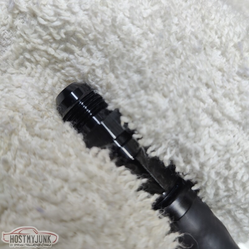
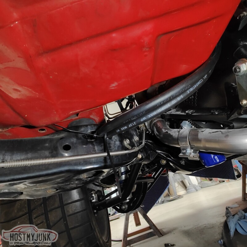
Today was another plumbing day. This time it was time to plumb the transmission cooler. Here is a little tip when working with push-lock style hose.
Add a union to the fitting and snug it down. This does two things:
1. If using a 45 or 90 degree fitting it keeps the nipple from trying to move around.
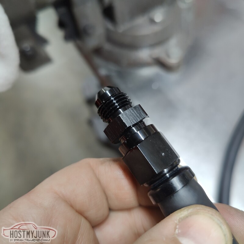
2. When putting the fitting in the vise to hold it, it keeps the the nut from crushing and becoming out of round.
This is the rear fitting on the transmission. The picture actually makes it look like there is a lot of clearance, but in reality it is very tight.
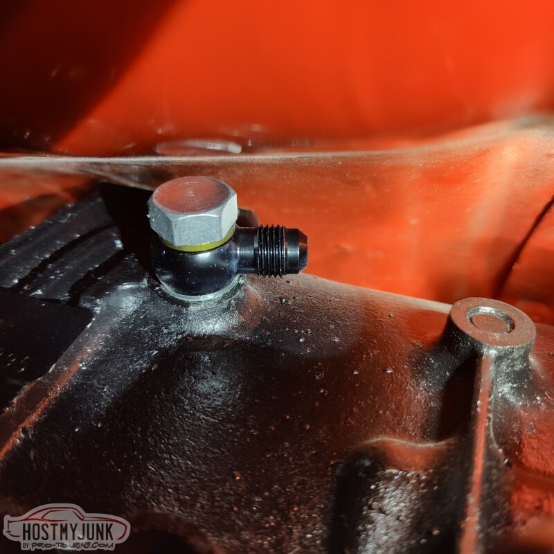
I managed to get the hose end started, but I will probably have to get creative with getting it tight. I think a Crow's foot should get it done.
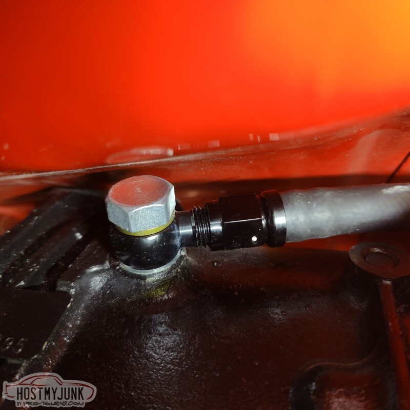
The front port wasn't too bad. I used a 45 degree fitting on this hose. Removing the trans dipstick made access easier.
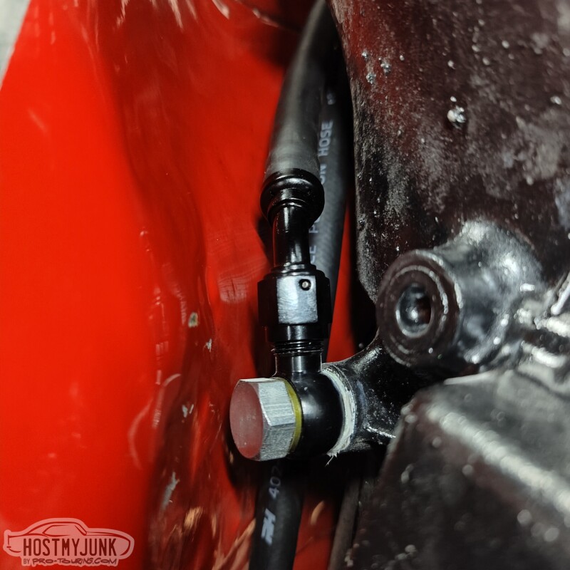
The hoses make a gently sweep over the bell housing area of the transmission, over to the driver's side, where they slip into a slot in the frame. This slot is where the factory hard lines were routed through the frame and out the front crossmember, by the steering box.
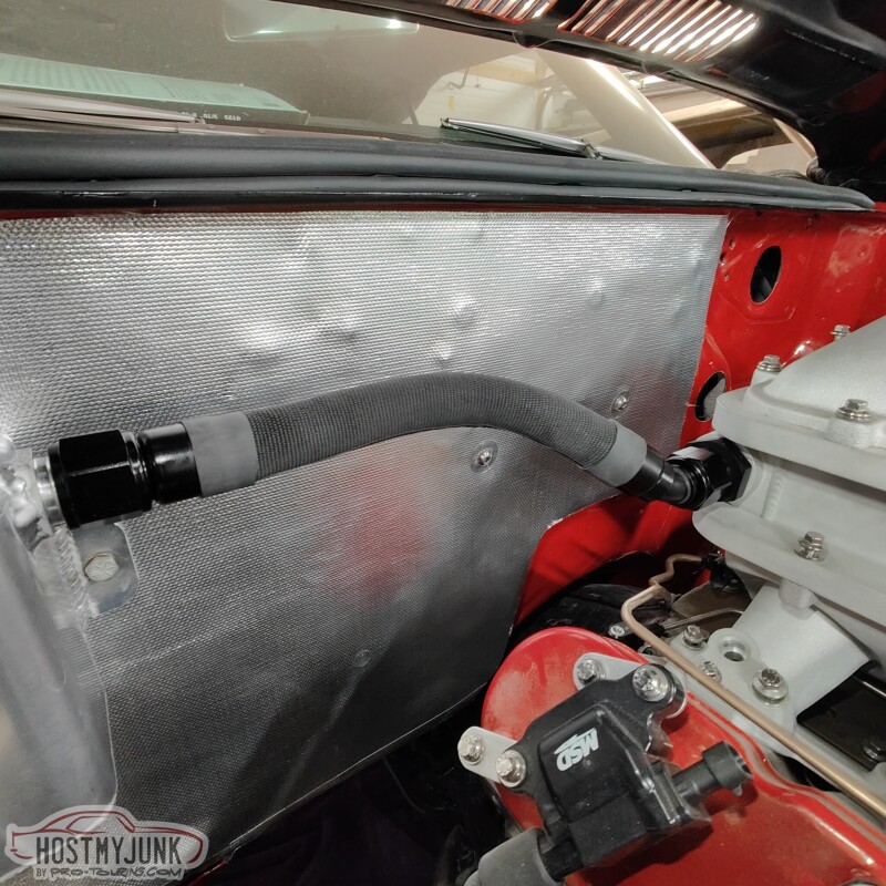
I also experimented with some covering material for the intercooler plumbing. This is a fabric heat shrink material.
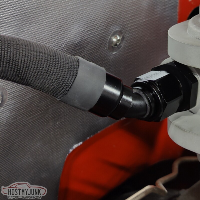
The ends are finished with heat shrink. This is a close-up to show the pattern and texture.
Andrew1970 GTO Version 3.0
1967 Cougar build
GM High-Tech Performance feature
My YouTube Channel Please Subscribe!
Instagram @projectgattago
Dr. EFI
I deliver what EFI promises.
Remote Holley EFI tuning.
Please get in touch if I can be of service.
"You were the gun, your voice was the trigger, your bravery was the barrel, your eyes were the bullets." ~ Her

 Reply With Quote