

Results 21 to 40 of 48
-
07-30-2019 #21
 Registered User
- Join Date
- Jul 2017
- Posts
- 166
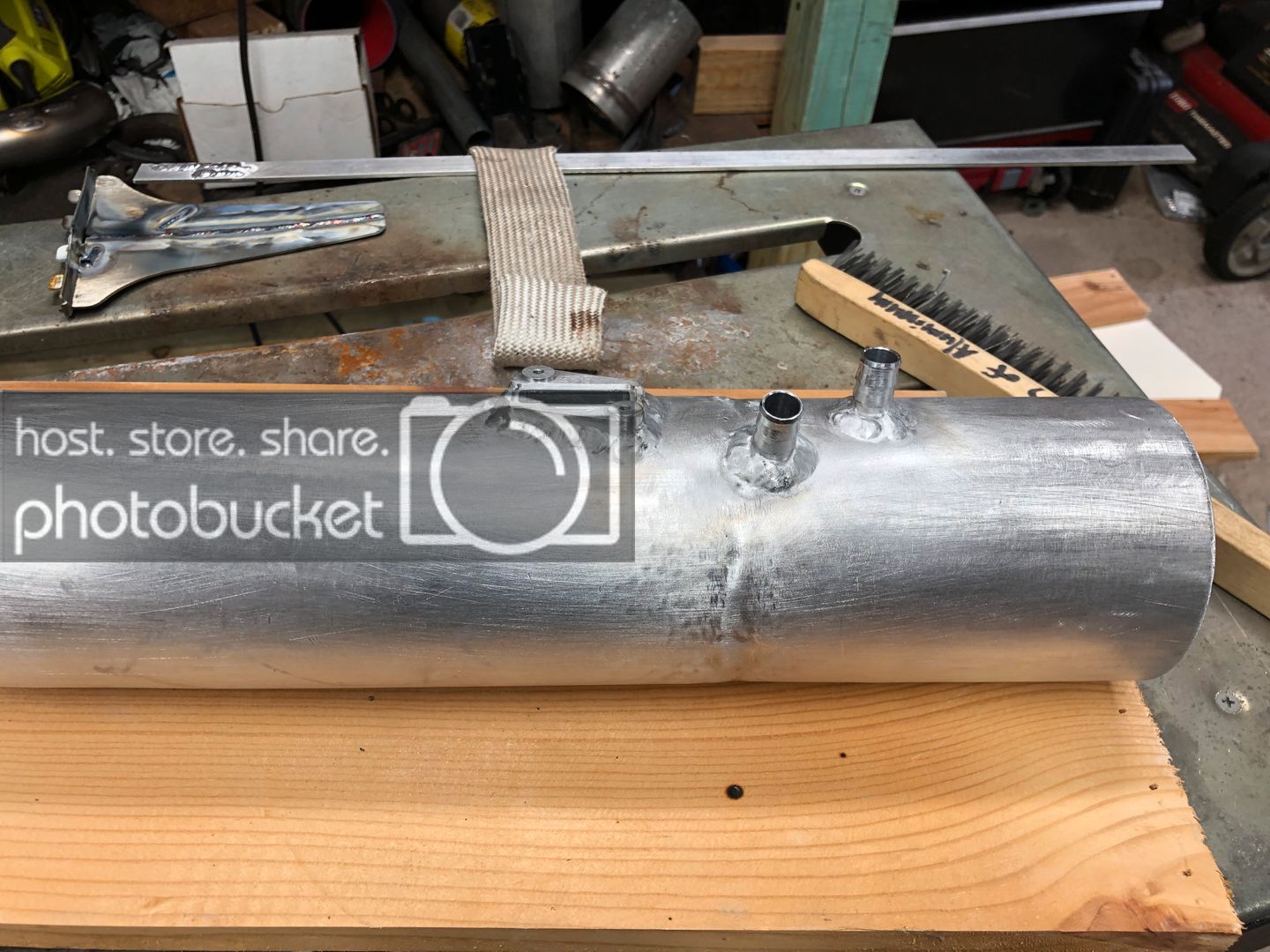
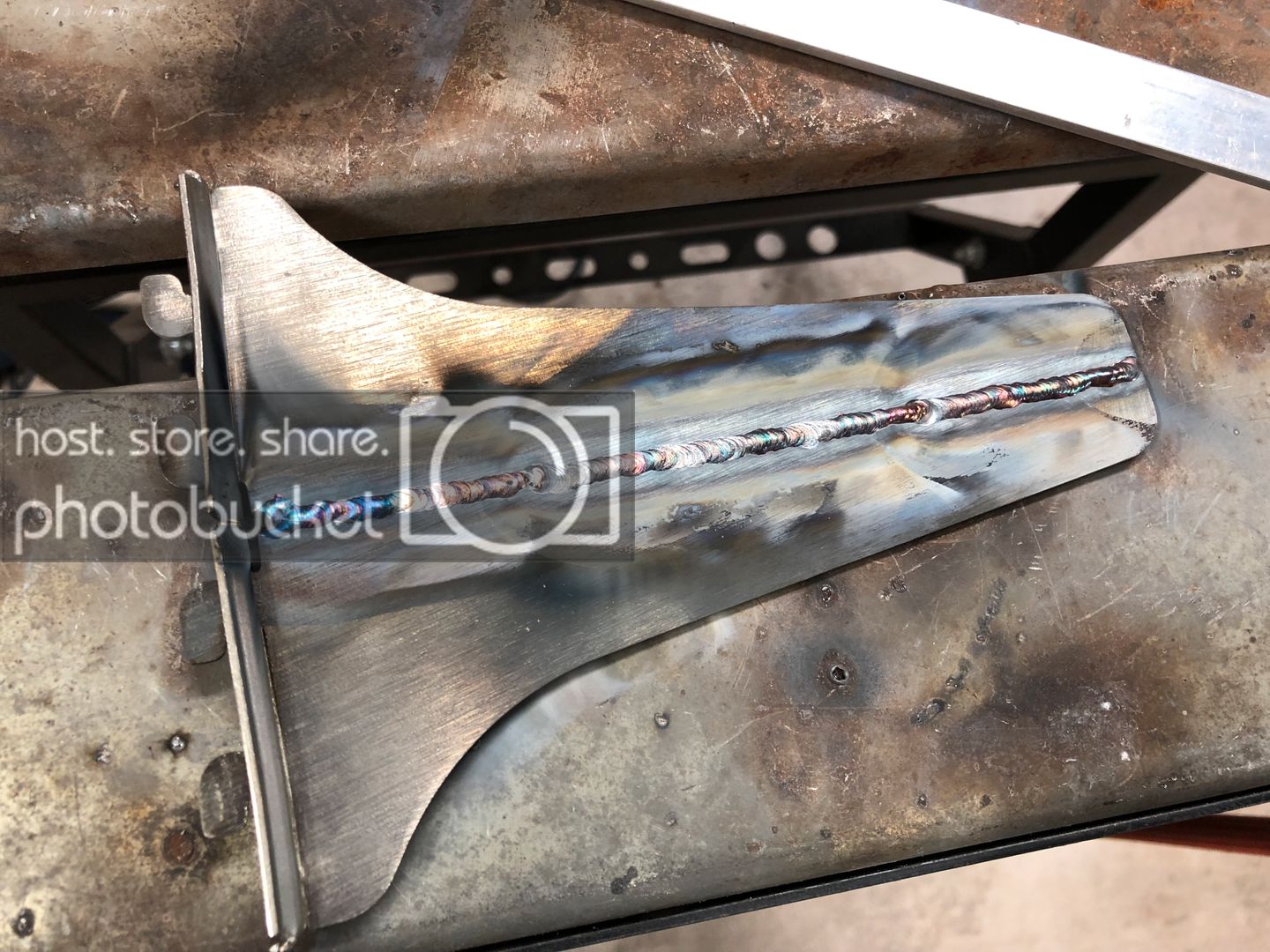
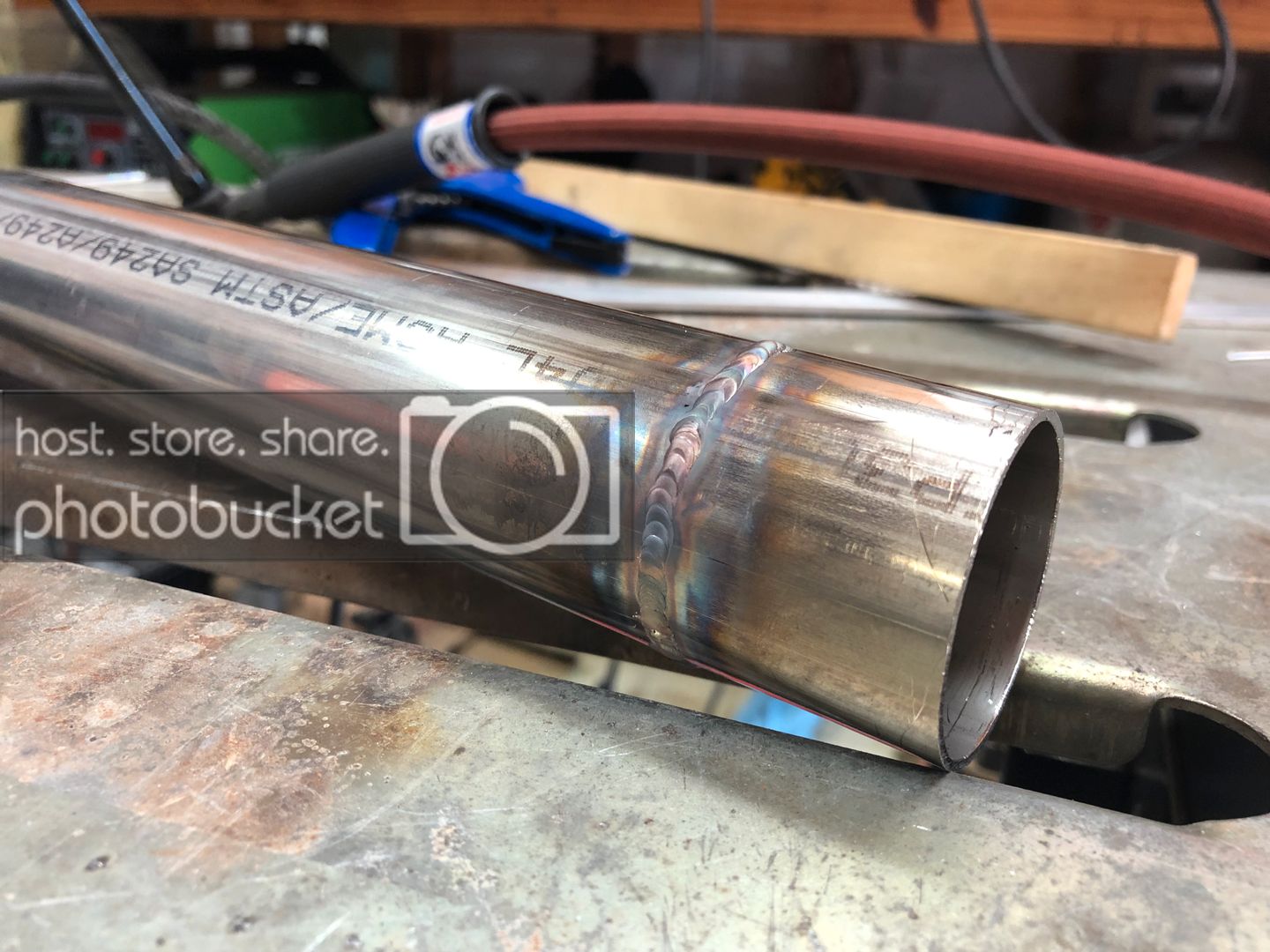
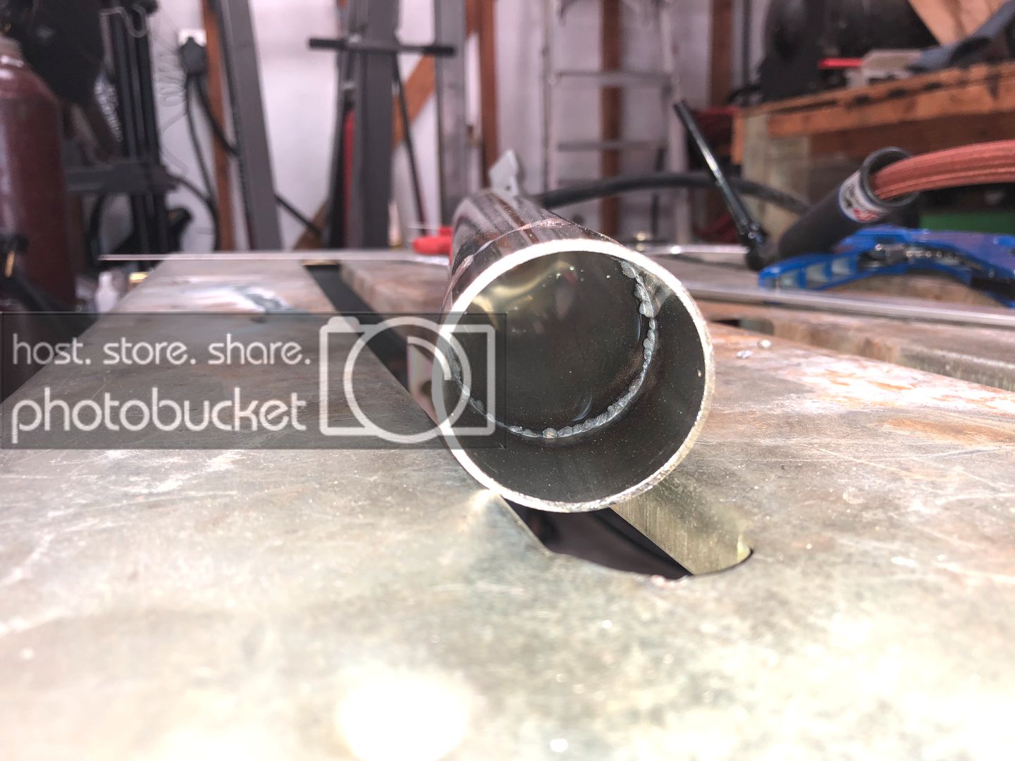
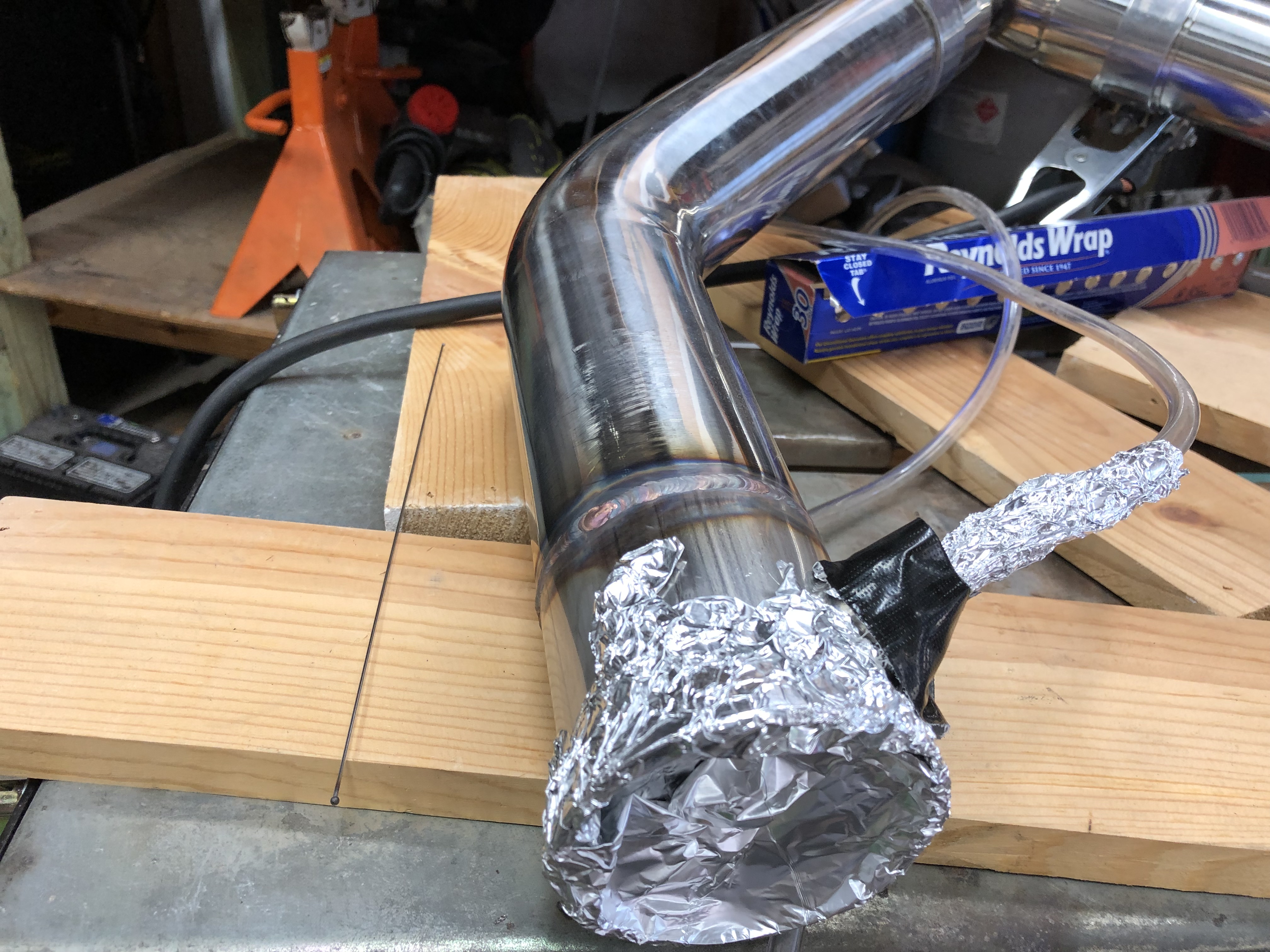
I was able to do a little more troubleshooting on my welding machine. Turns out the flow meter was way off, I purchased an external flow gauge to find out. It requires roughly twice as much air to achieve the correct CFH. With running the machine in DC you dont notice it as much but while in AC on aluminum it was horrible. Below is a picture of the 1/2" bungs I welded on the bottom of the intake, they were very rough and I cleaned them up a hair after the machine was operating normal again. Also laid down some SS welds to see if they would be better than before with the correct CFH and they look a little better than before. Did a little practice without a back purge on some 304 tubing to do a little practice for my upcoming exhaust build I'll be doing soon. If you are unaware, you need a purge or flux to protect the back side of the stainless welds from oxygen due to the stainless being reactive while welding, it will look like crap as seen in the photo below.
-
07-31-2019 #22
Registered User
- Join Date
- Jul 2017
- Posts
- 166
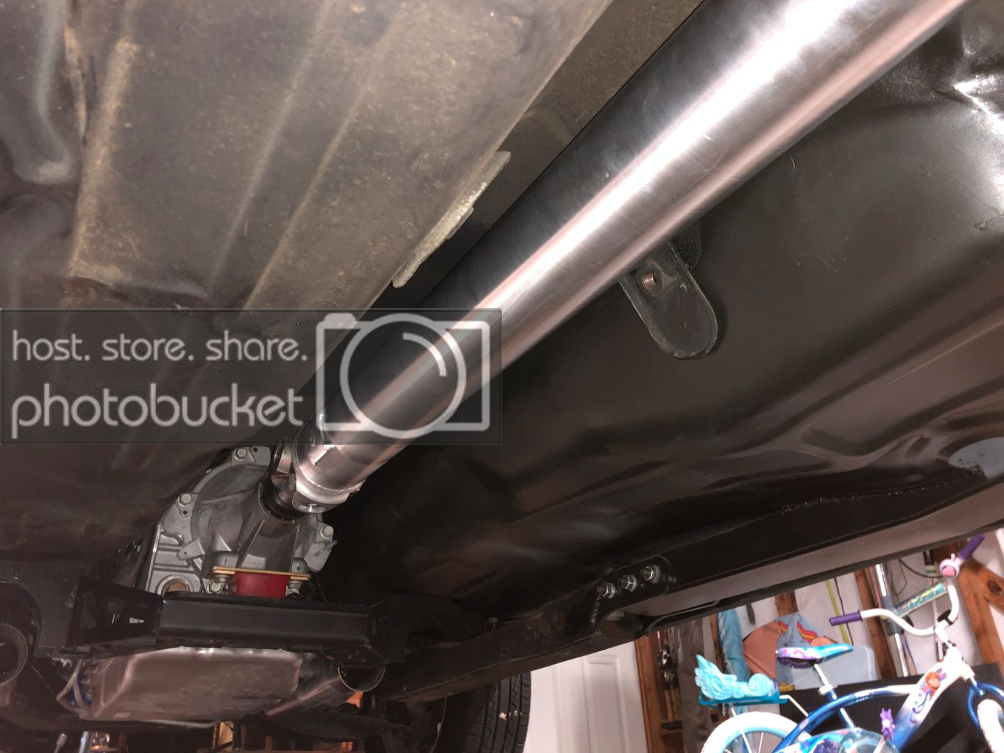
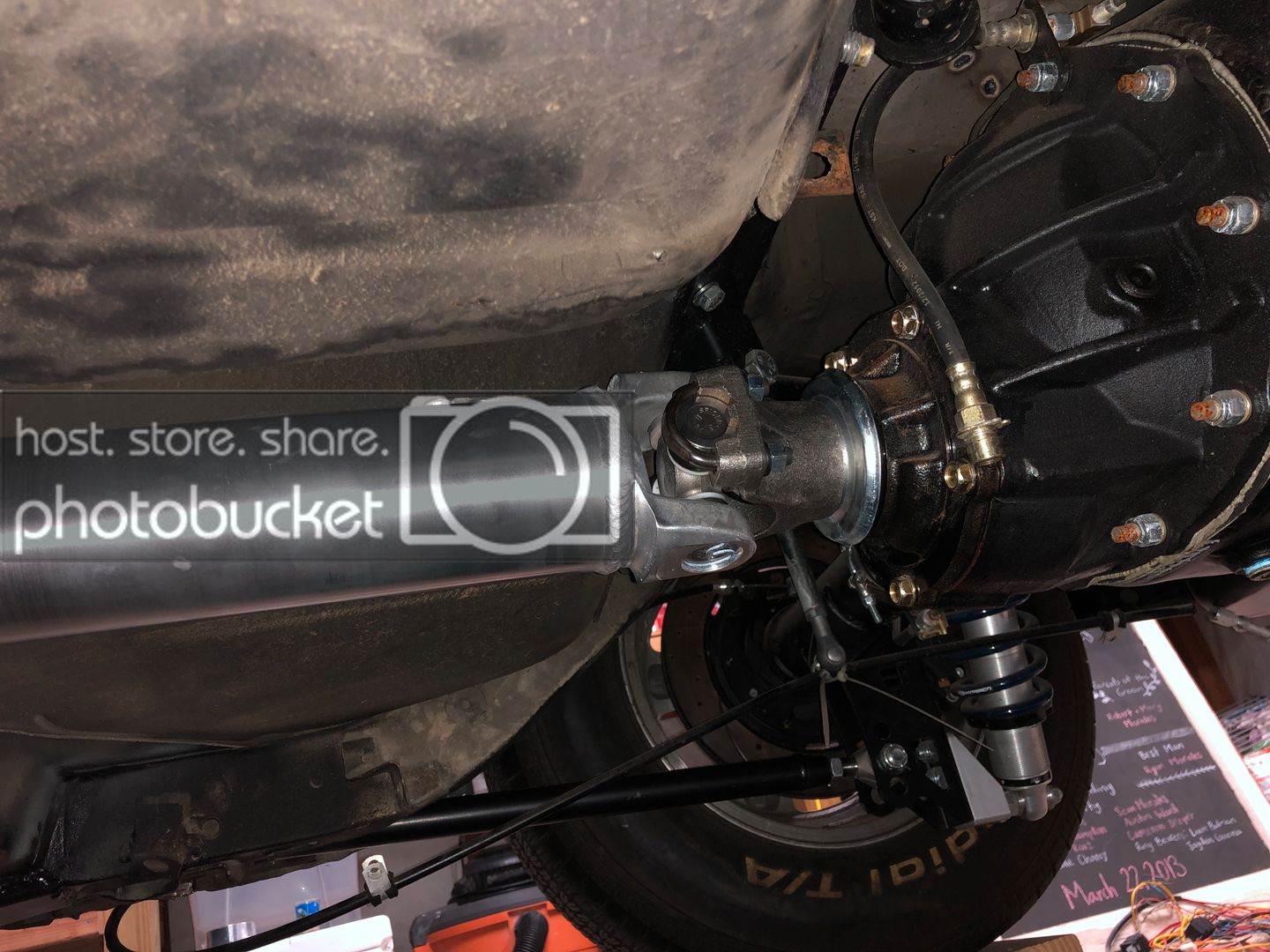
I got a driveshaft ordered from Inland Empire and it looks pretty nice. The customer service was great and they helped me to get the correct yoke for the 10-speed. I had a brain fart though... I ordered the driveshaft with a 1350 series u-joint for my rearend because I was 100% sure thats what I was running. Turns out I had the 1330 series pinion yoke installed. Ended up purchasing a 1350 pinion yoke to solve the problem. Now I have two extra pinion yokes if someone wants one since Curry sent me the incorrect 1310 yoke initially and now I have the extra 1330 yoke.
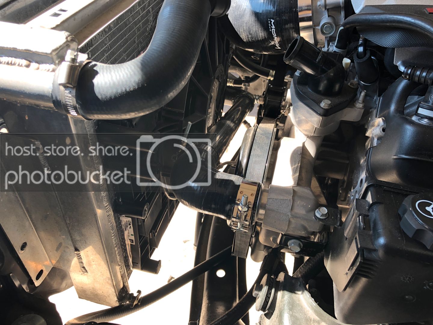
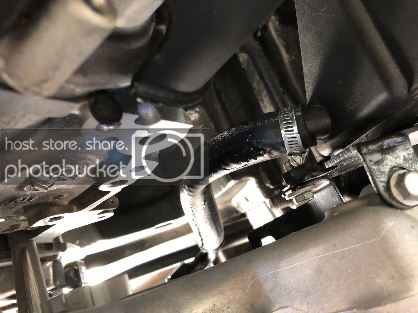
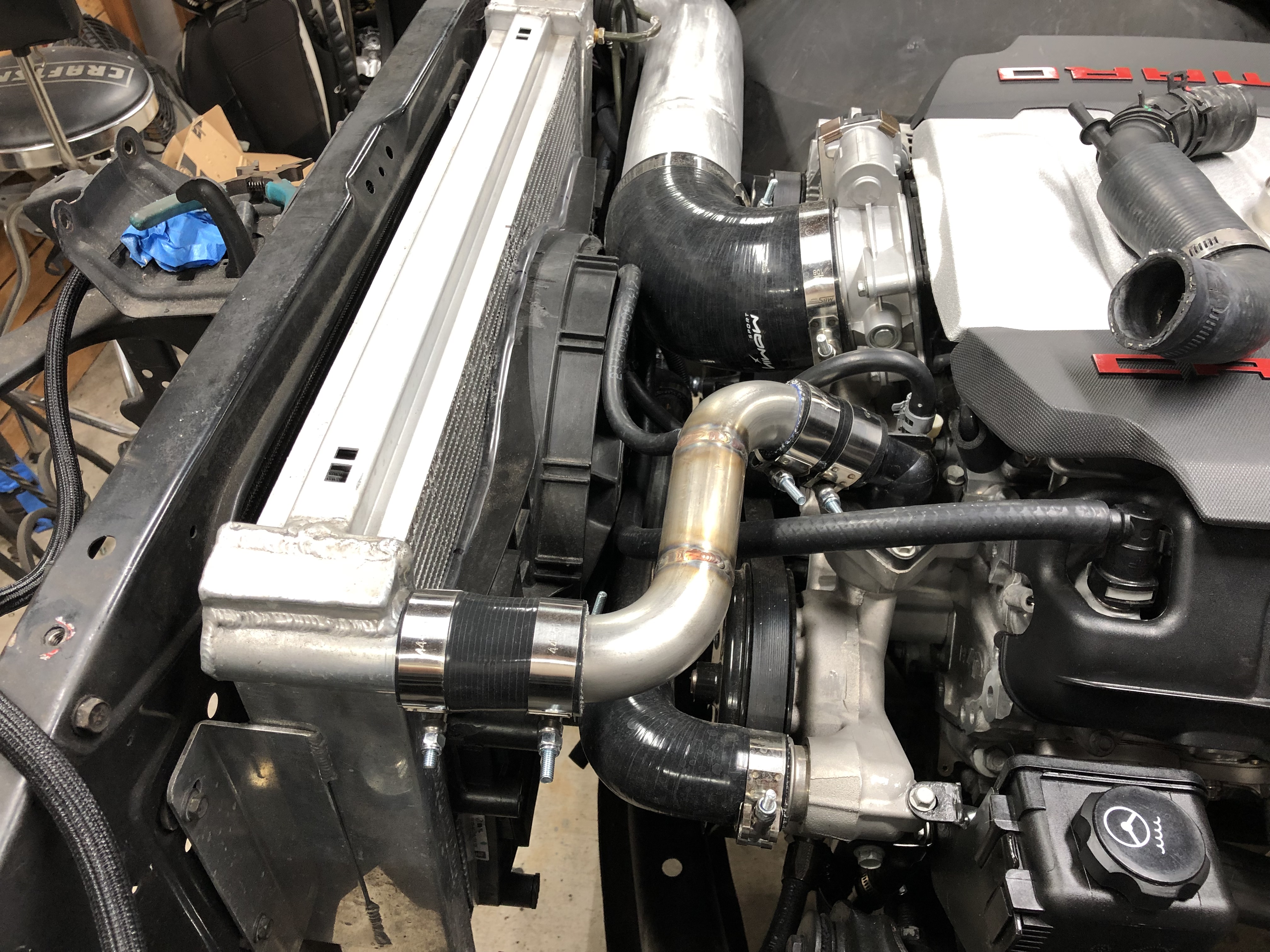
I was able to install the lower radiator hose too, I just used some 1.75" SS tubing and silicone elbows to connect it. I'll be working on the upper hose in the next few weeks. What I have now does not look very appealing so I'll use more SS tubing to match the lower section.
I'm always learning and I have never really made custom lines for power steering so this was a learning experience. Turns out that you cannot use leftover 5/8" heater hose for the power steering reservoir feed hose. The hose looks like it is sweating fluid out of it, the fluid just ate its way through the hose. I purchased some actual PS hose and swapped it out. This had me question the return line coming off the steering box to the reservoir. This was also leftover hose from the fuel system and from what I was reading fuel hose cannot be used either. I contacted the manufacture of the hose and they said it will be fine as long as its on the lower pressure side as the hose is rated for PS fluid.
08-06-2019 #23
Registered User
- Join Date
- Jul 2017
- Posts
- 166
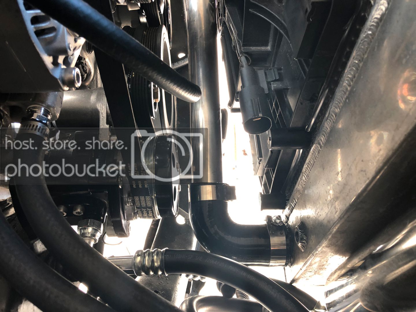
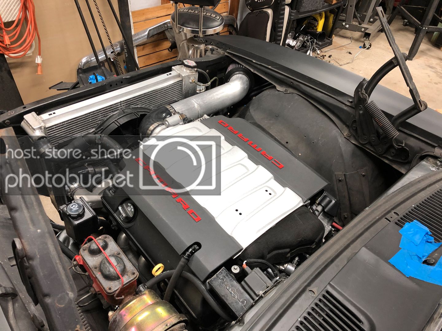
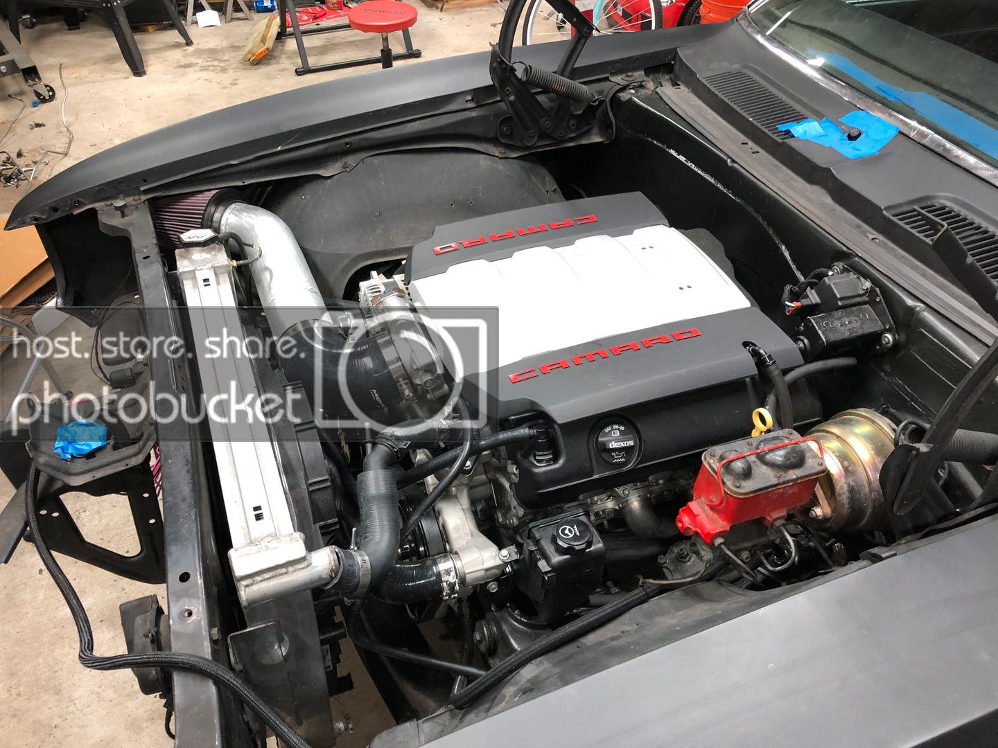
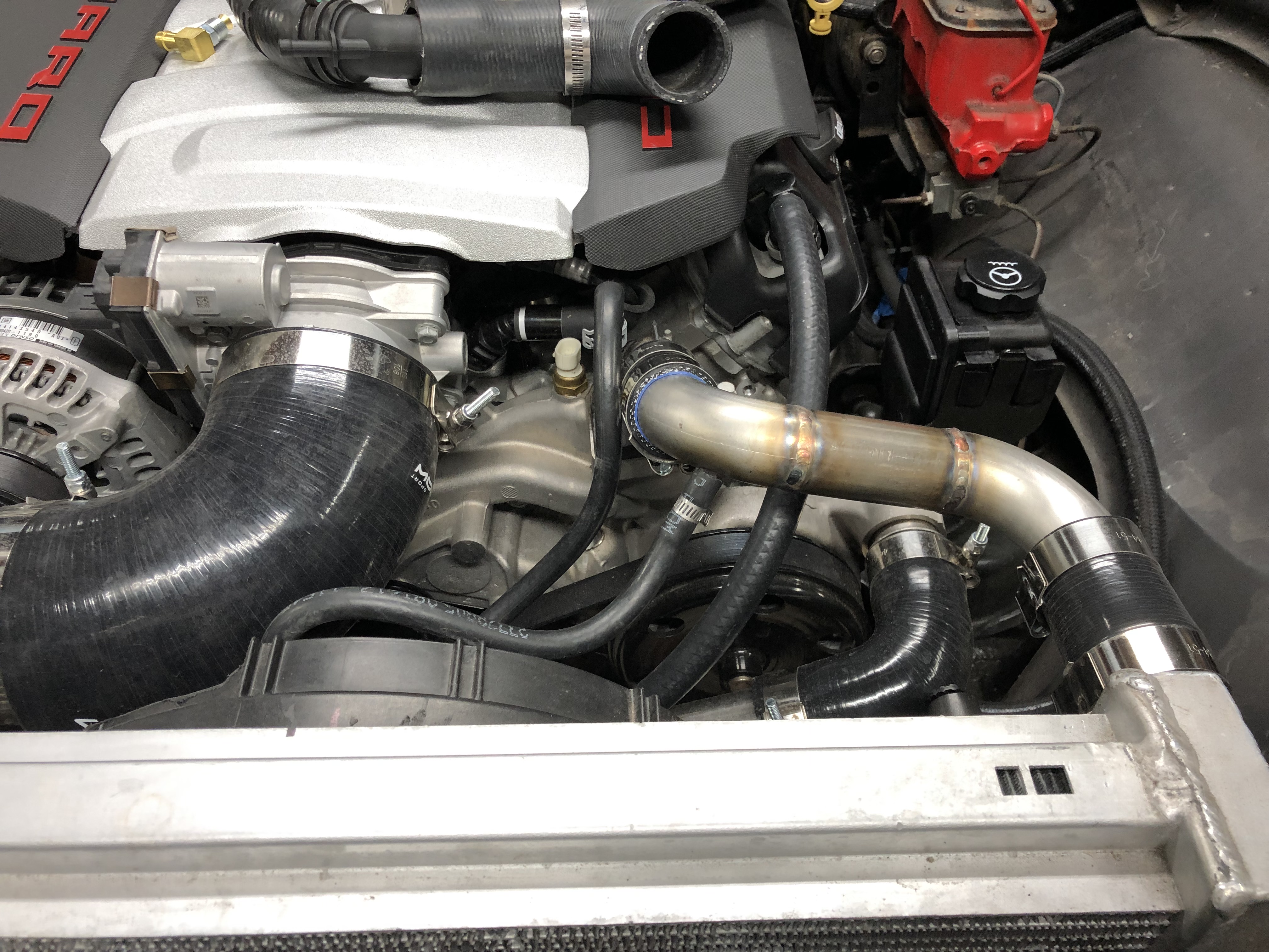
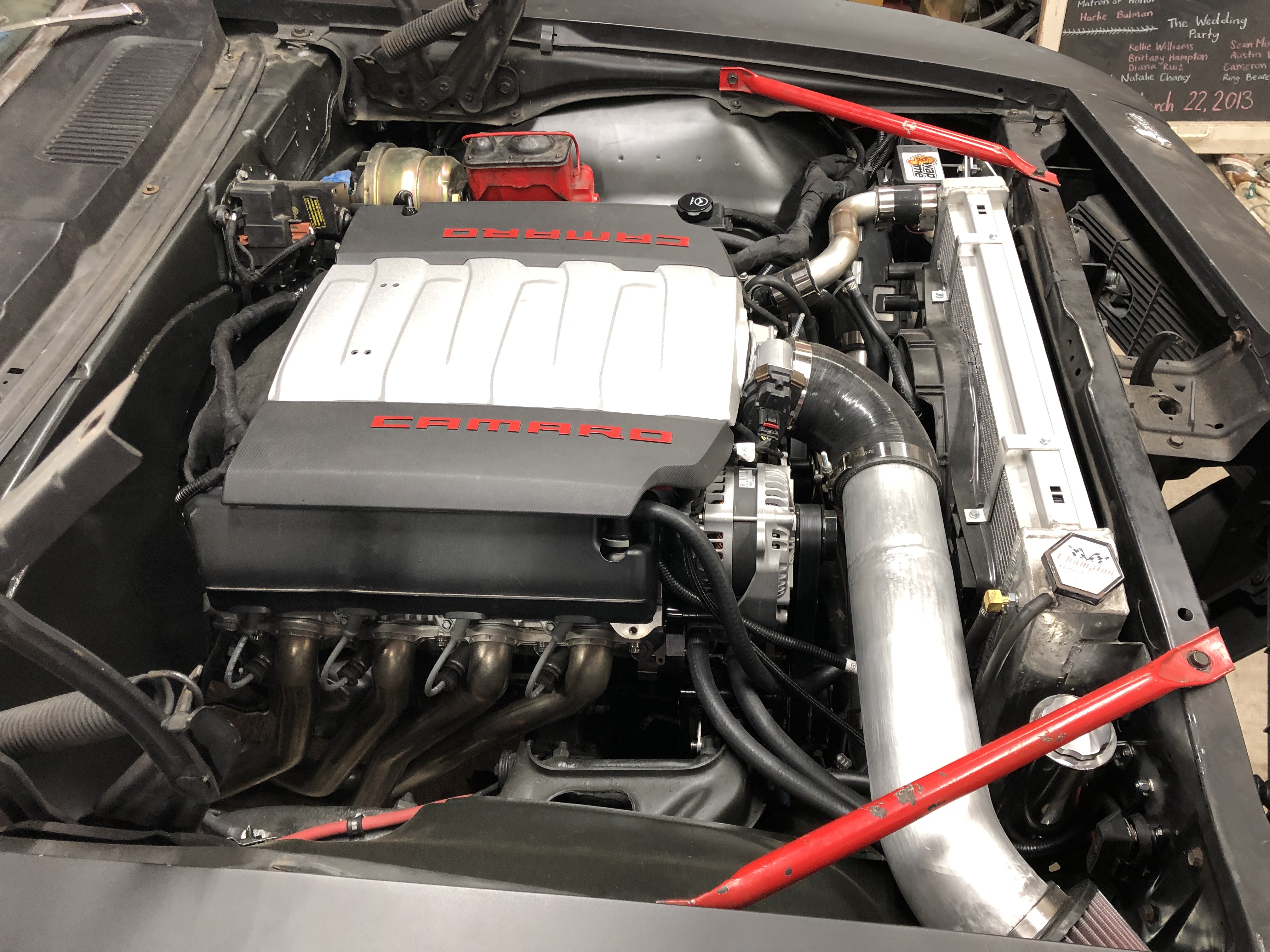
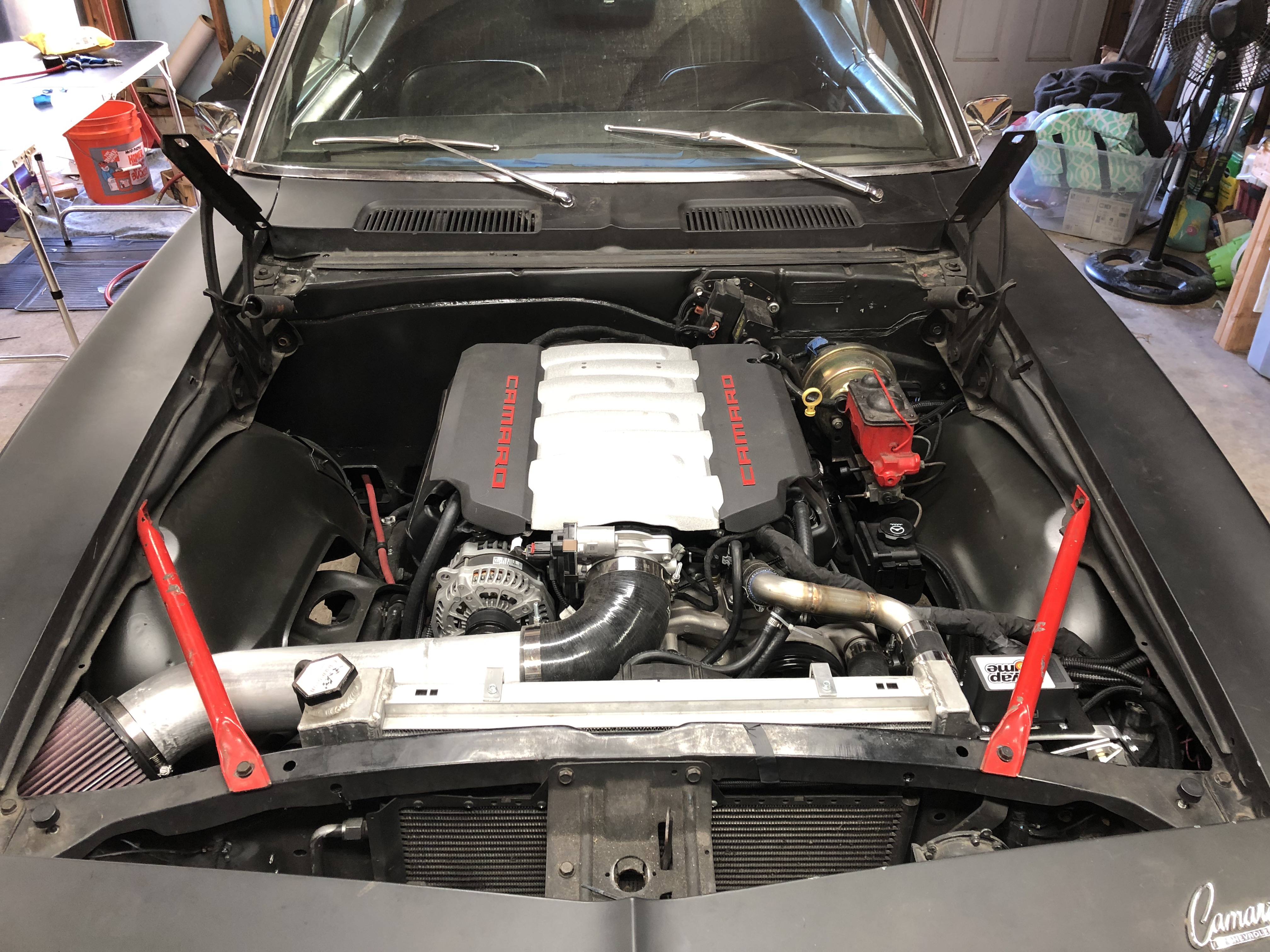
Here's a few pictures of the engine bay after I fixed the PS line and installed the air filter. I also ran the trans lines to the radiator but did not like how it turned out, I could not get a tight enough 90 degree bend to clear the intake. I ordered a tight radius 90 and I'm planning on changing this once I get the new part. Got the new rear brake line installed and hooked up the ebrakes, just need to bleed the brakes and adjust the ebrakes accordingly.
Just waiting on the engine harness and I'll be starting the exhaust in then next few weeks. Maybe a few other little things left and then I'll be able to start it.
09-17-2019 #24
Registered User
- Join Date
- Jul 2017
- Posts
- 166
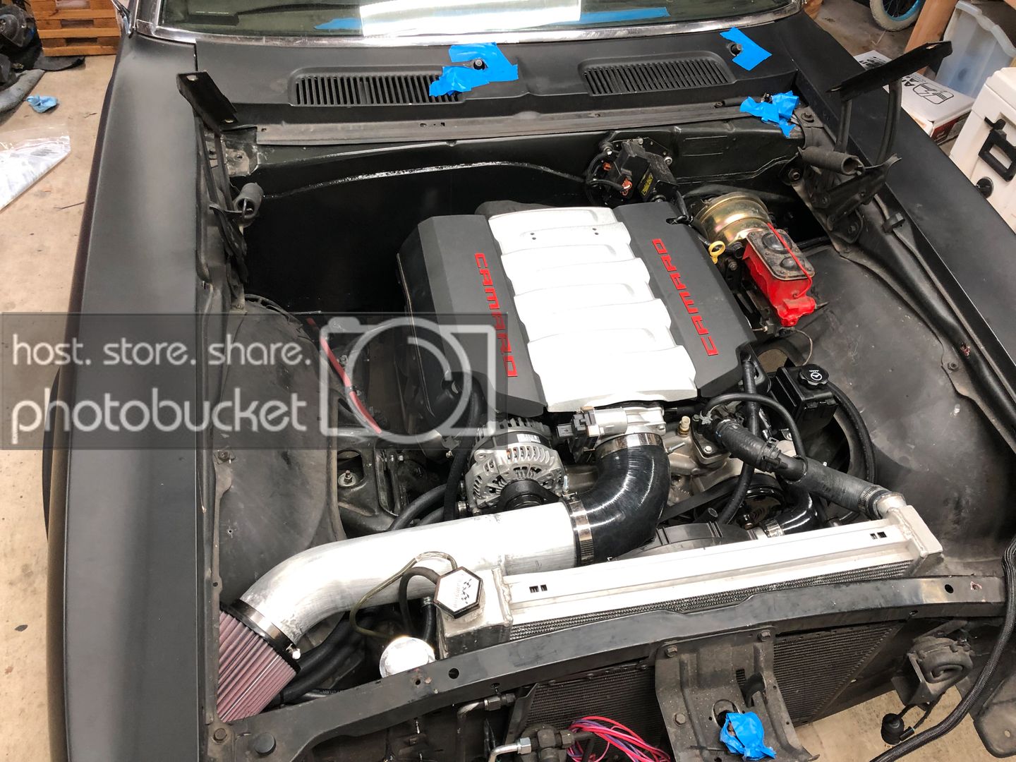
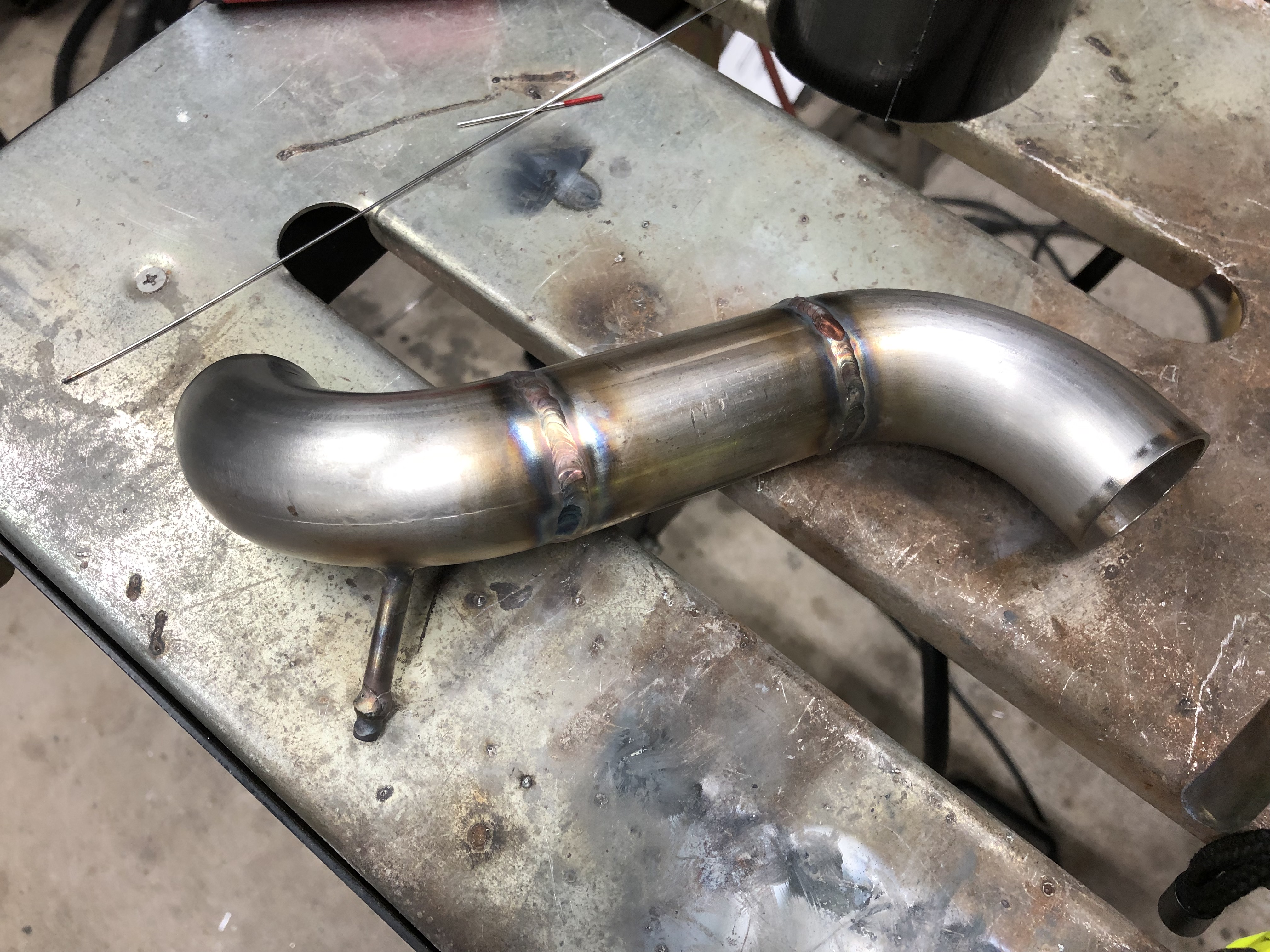
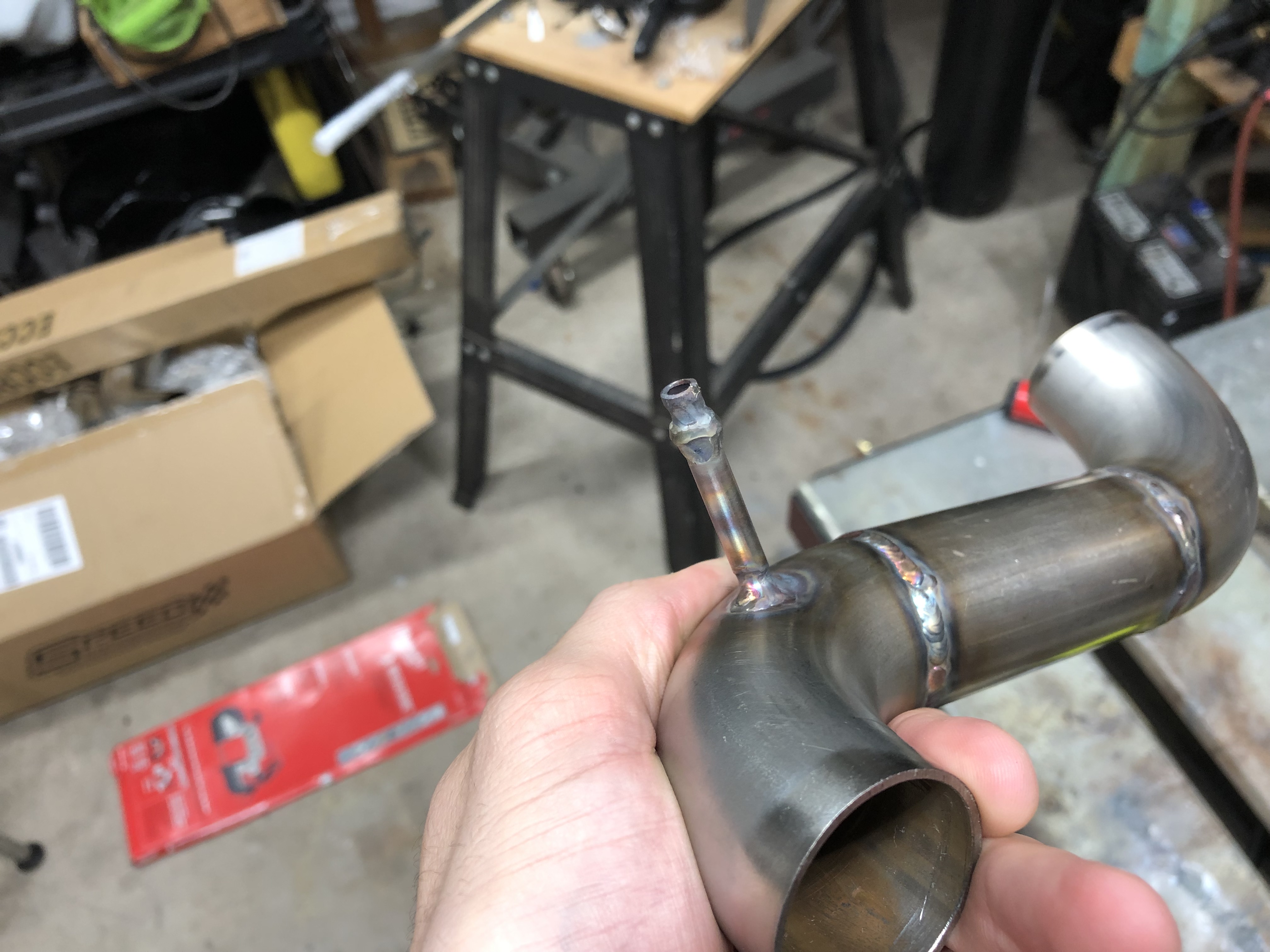
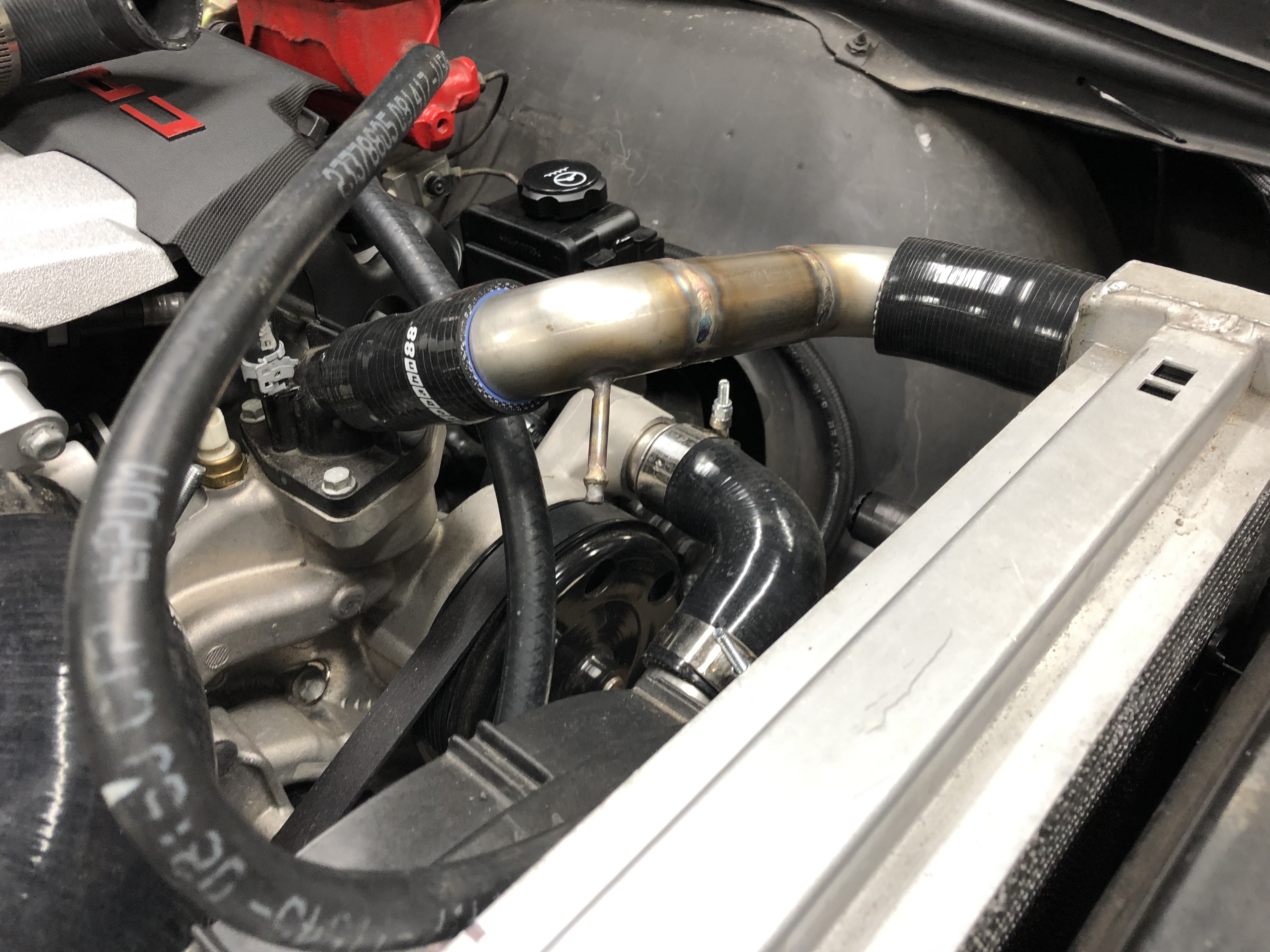
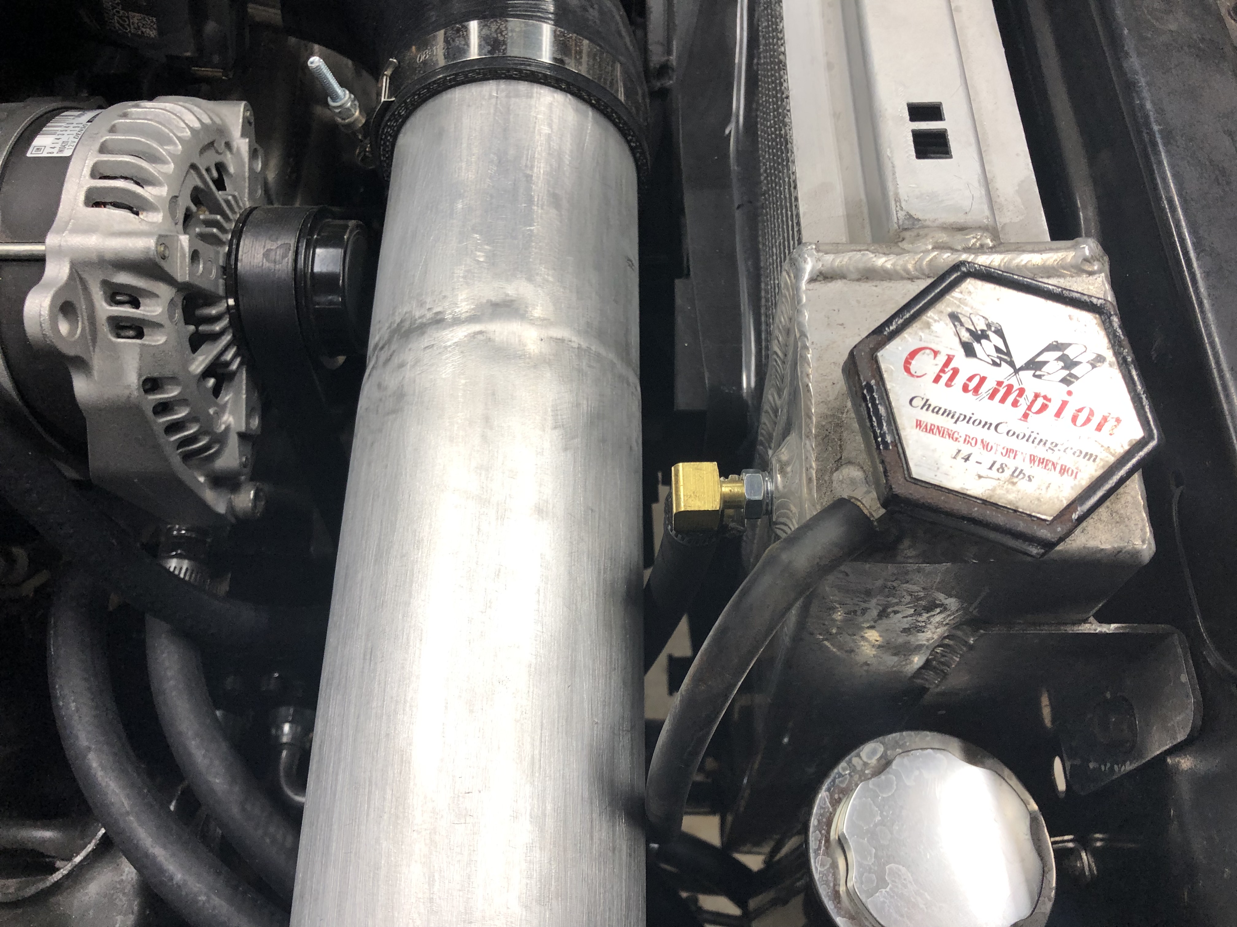
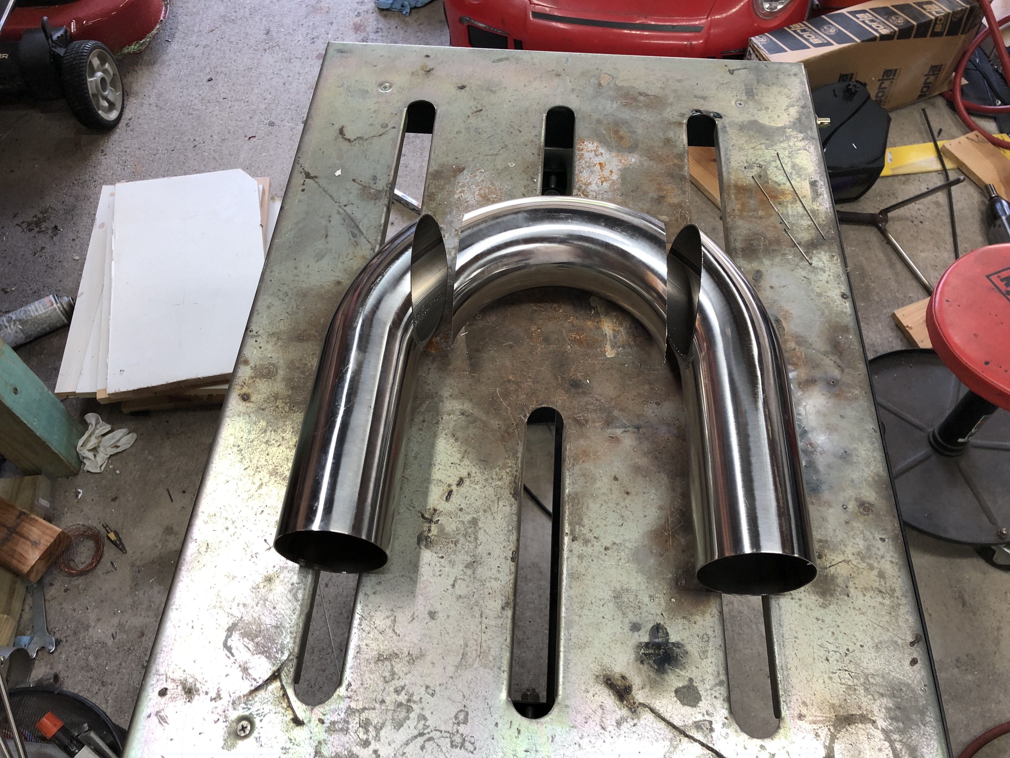
I got some 1.5" 304 tubing to build my upper radiator hose rather than use what you have seen in the previous photos. It only took about an hour or so and looks a lot better to cut up a U bend and make a few welds. I also incorporated a 1/4" tube to be used as the steam port. The 1/4" tube runs through the 1/5" tube and is extended in enough so it hits the high point of the system. These parts and a few couplers and t-bolt clams made it all fit nicely.
I have also changed the trans cooler line fitting at the radiator to make for a cleaner look.
09-17-2019 #25
Registered User
- Join Date
- Oct 2018
- Location
- San Jose, CA
- Posts
- 523
nice progress!
1971 Camaro - 406 / T56
2016 Camaro SS convertible
2018 Colorado 4x4
09-20-2019 #26
Registered User
- Join Date
- Jul 2017
- Posts
- 166
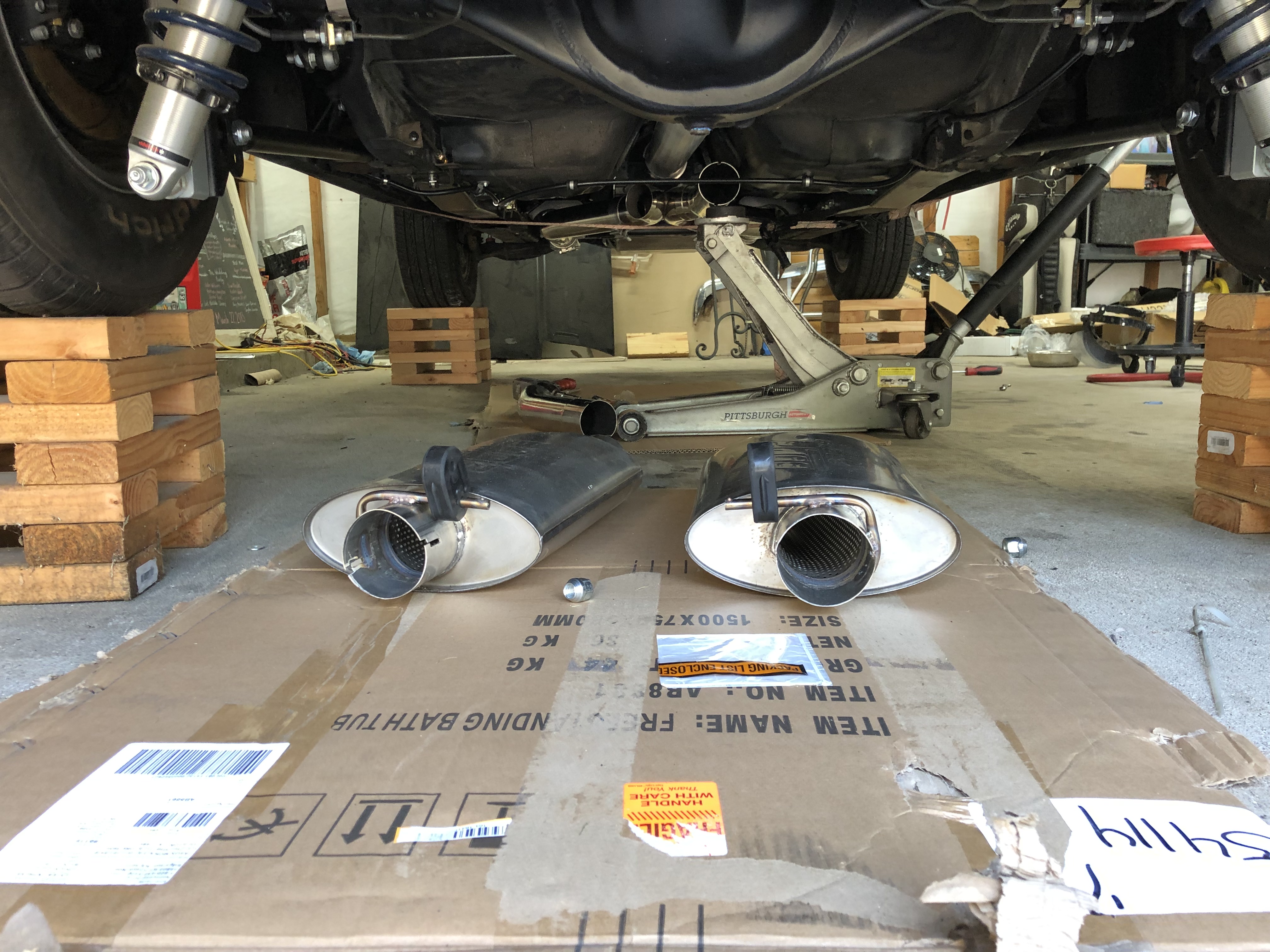
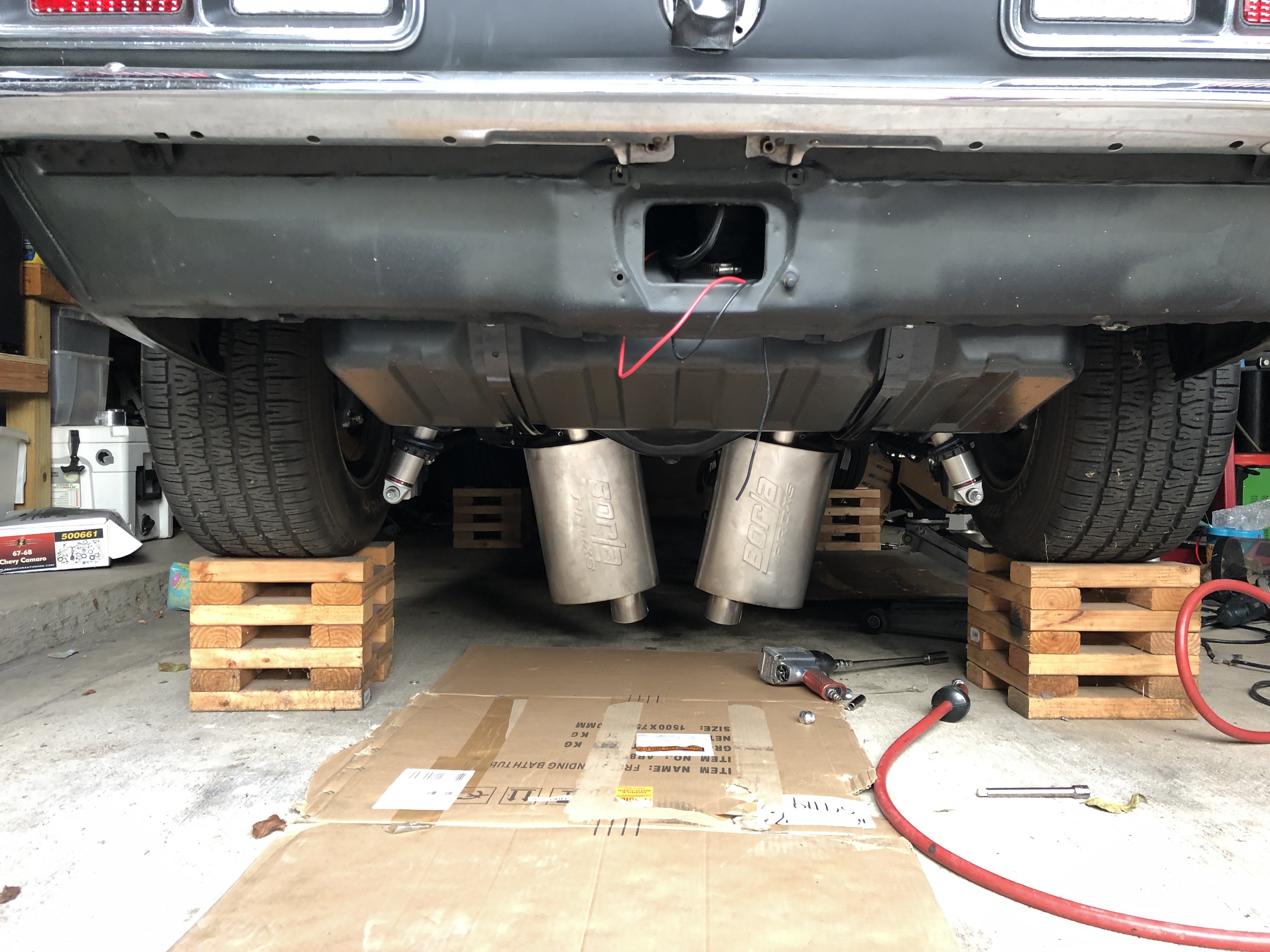
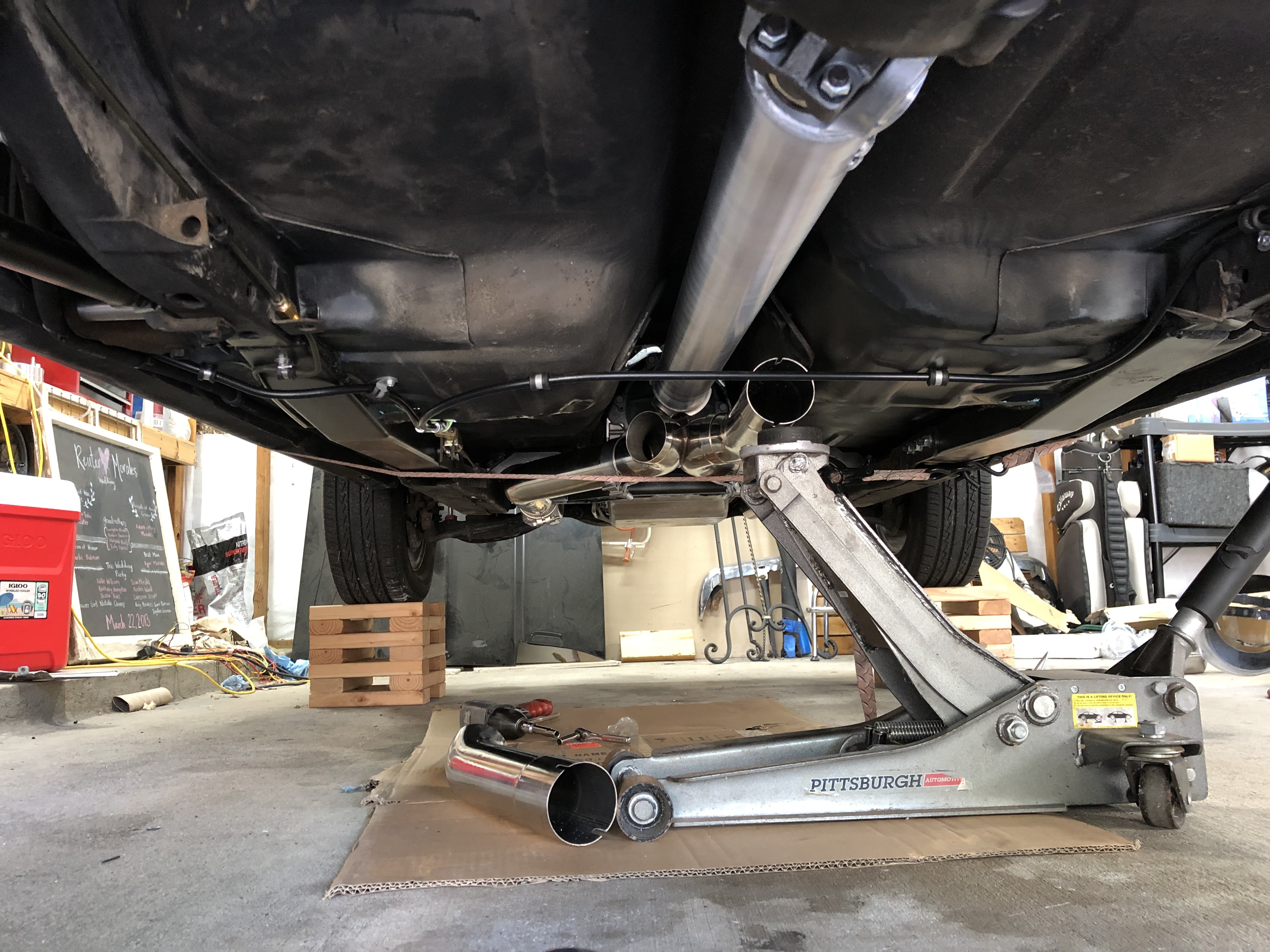
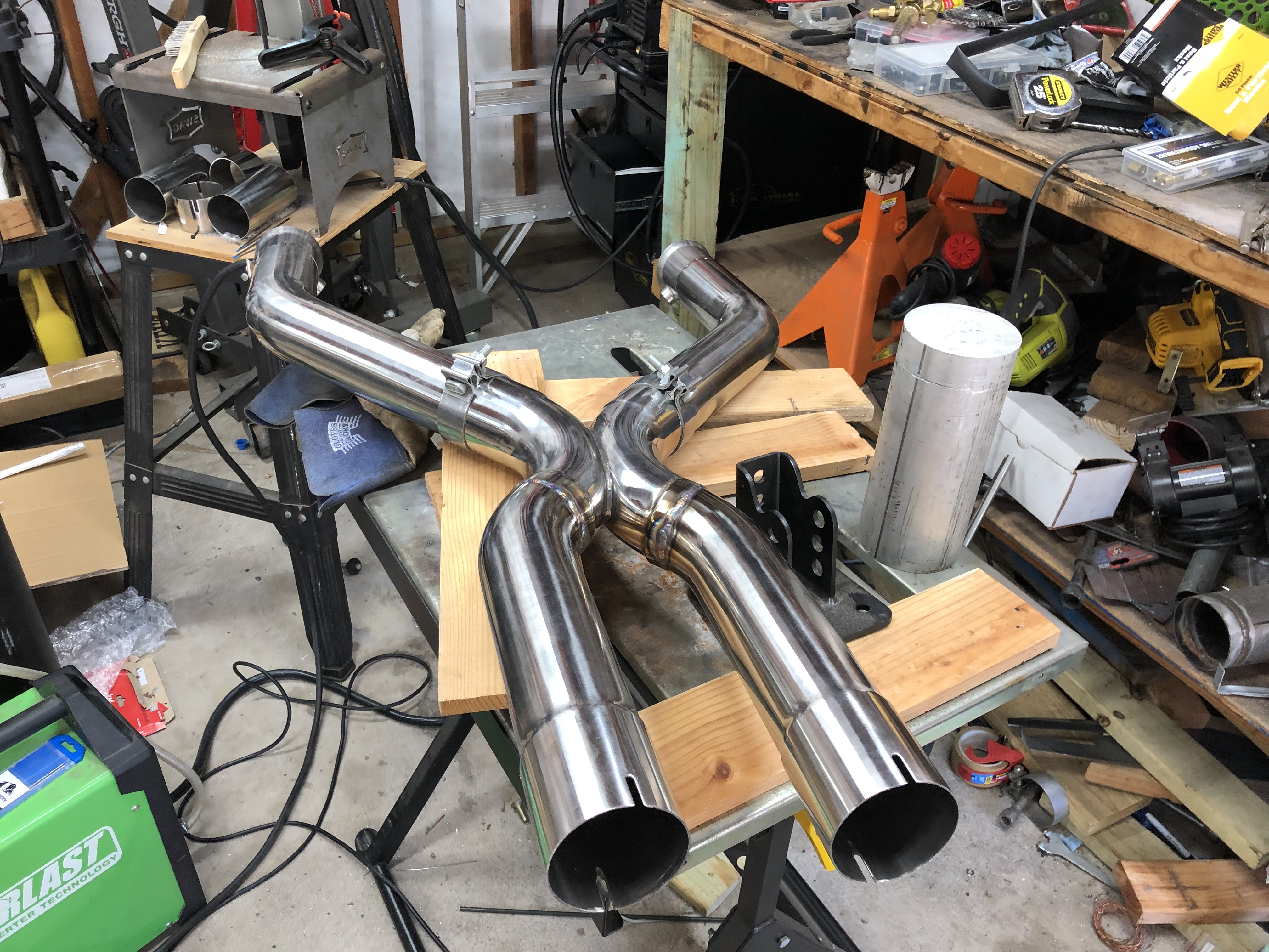
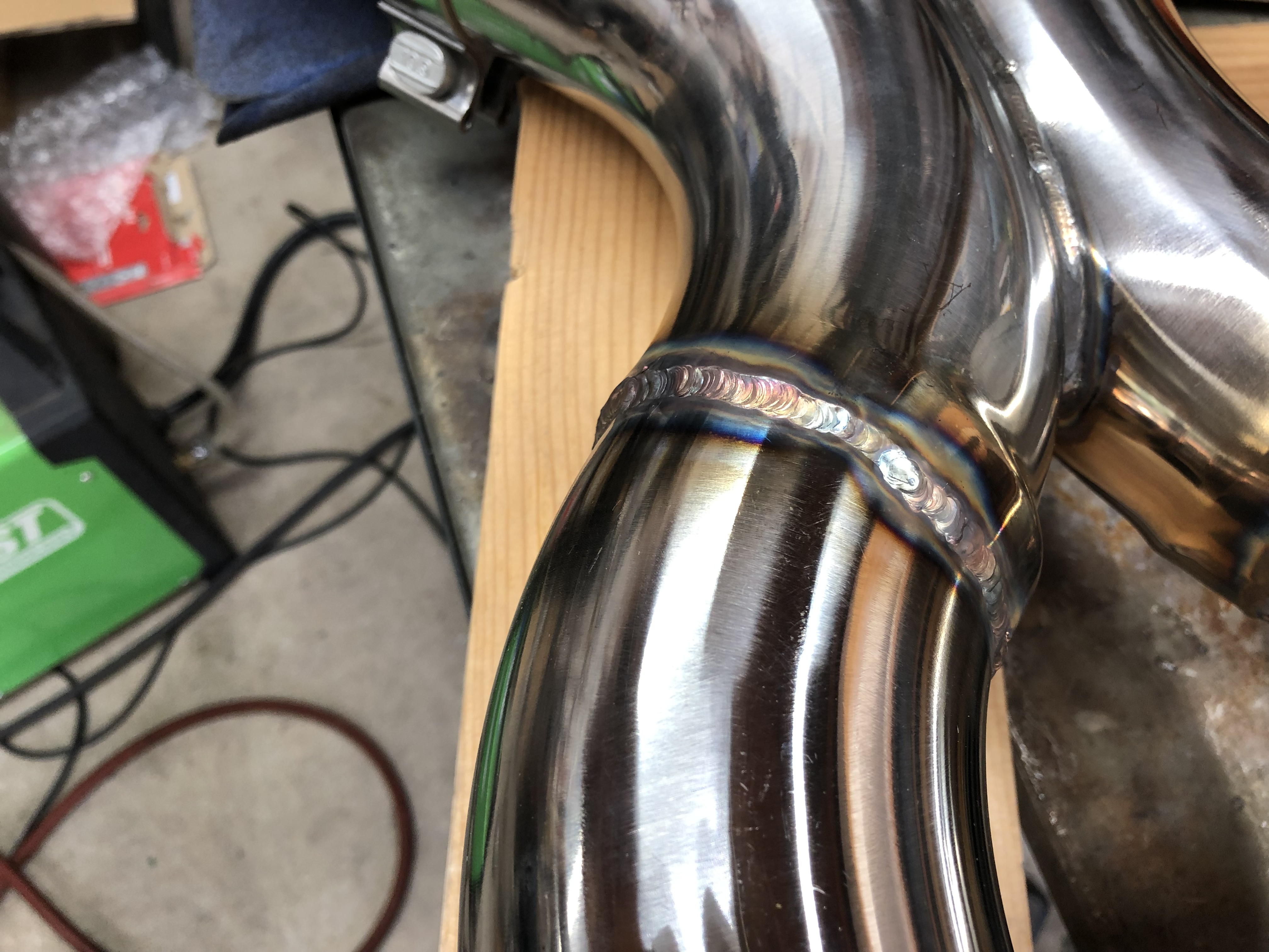
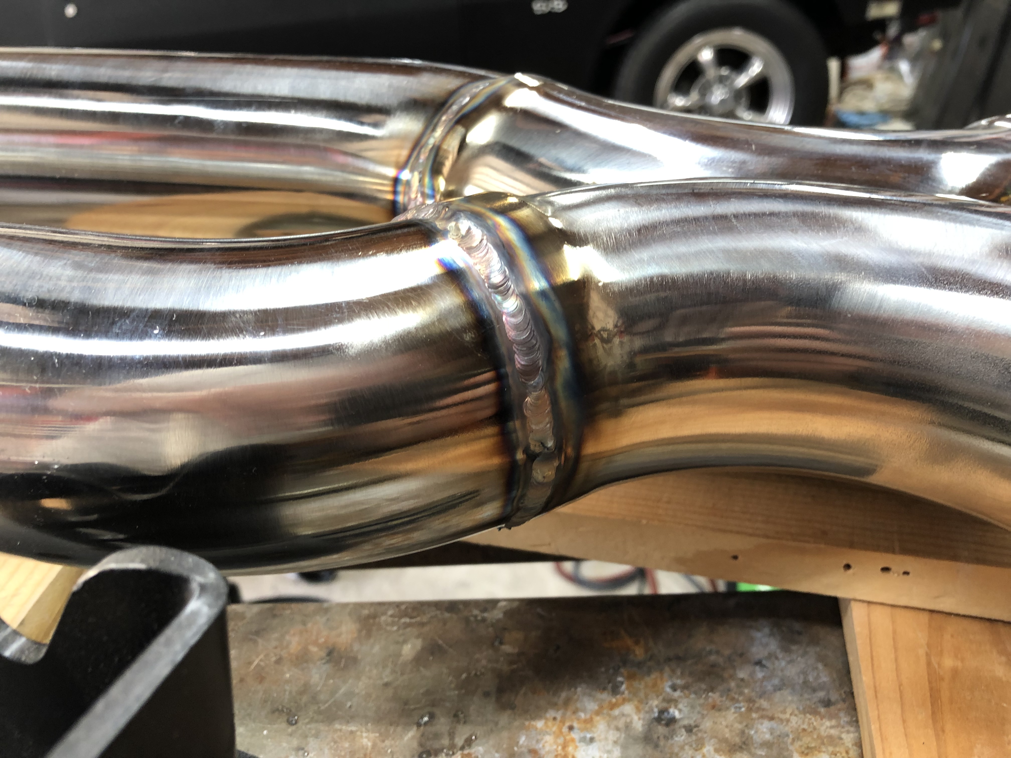
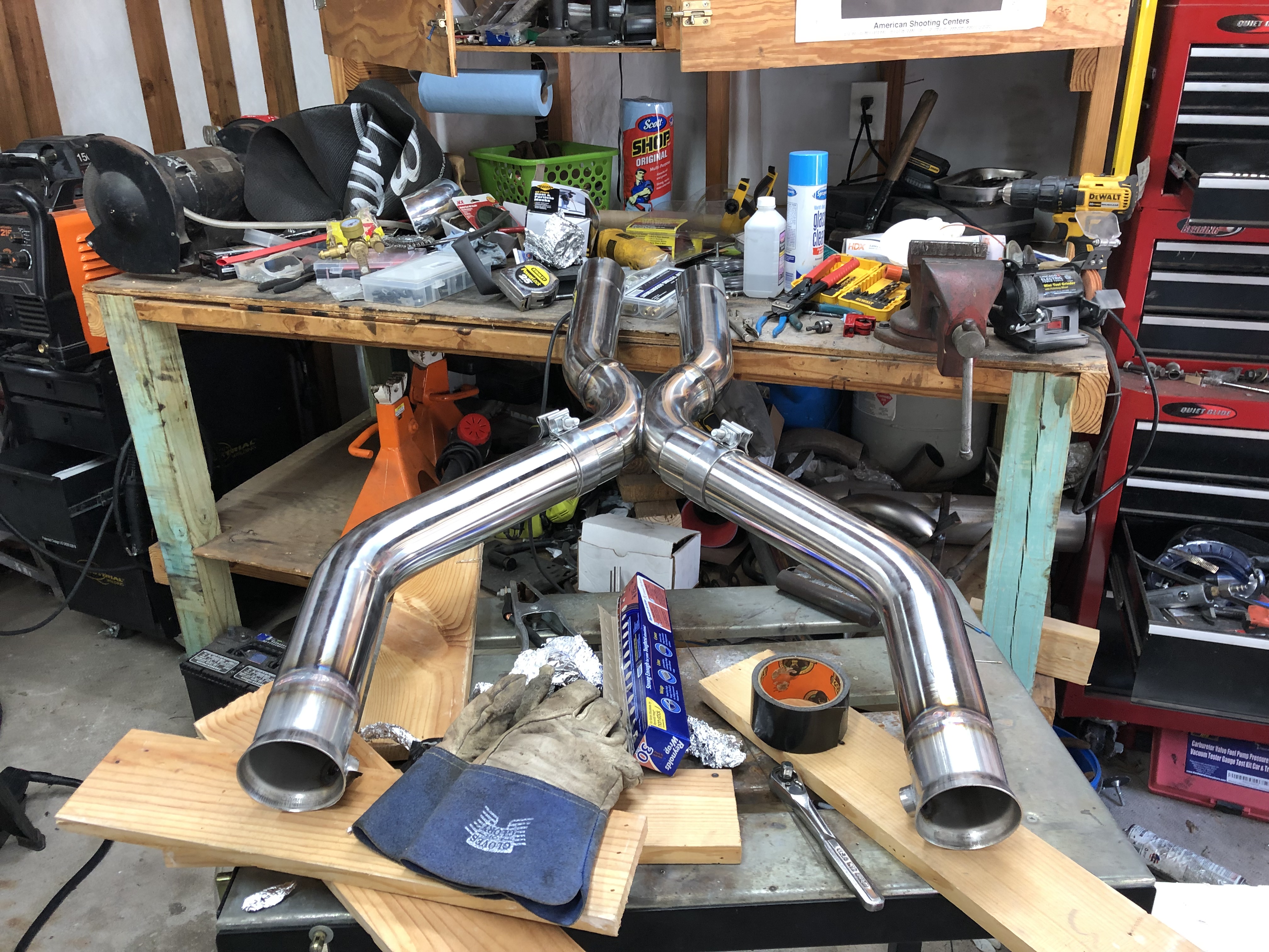
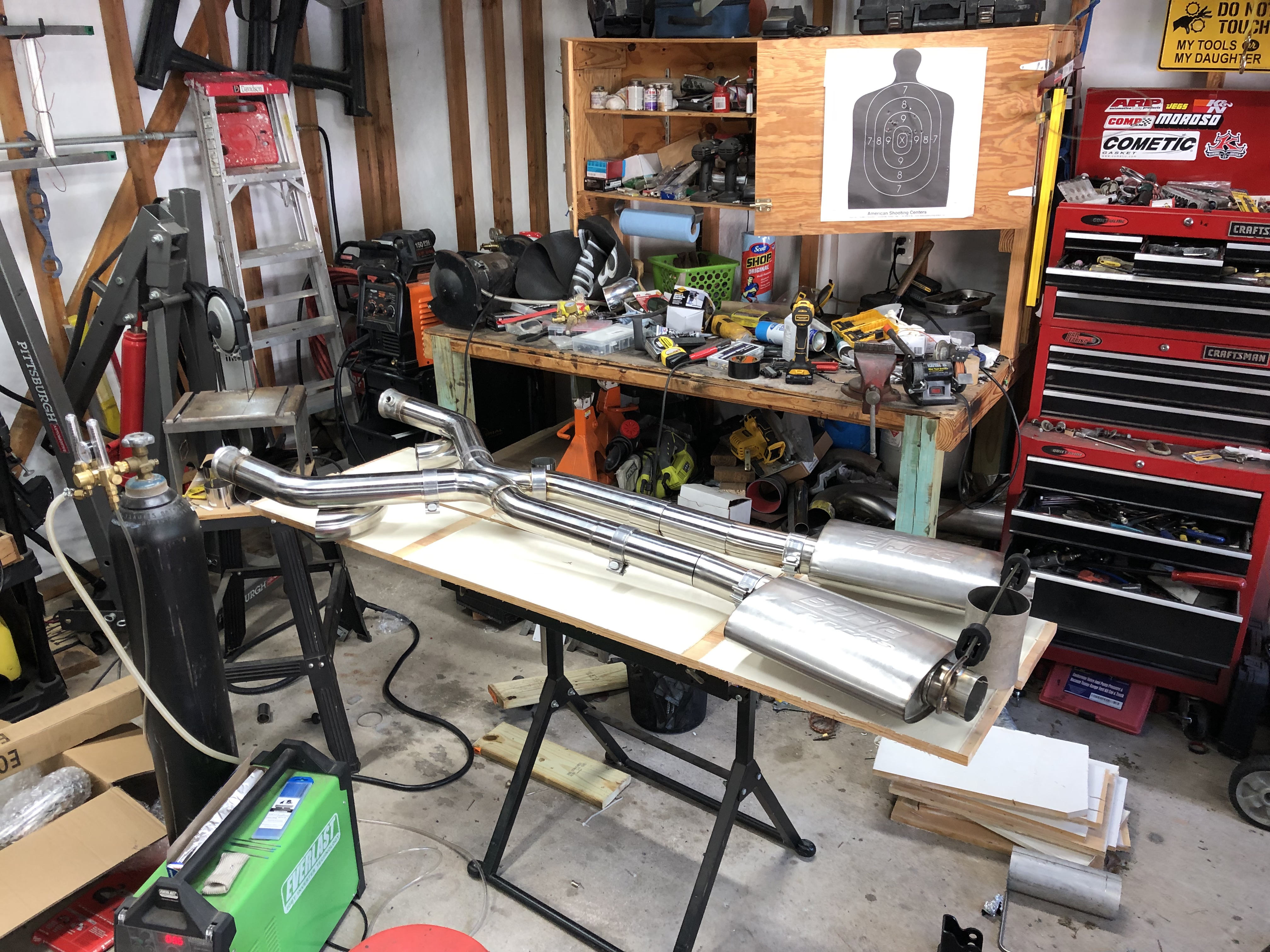
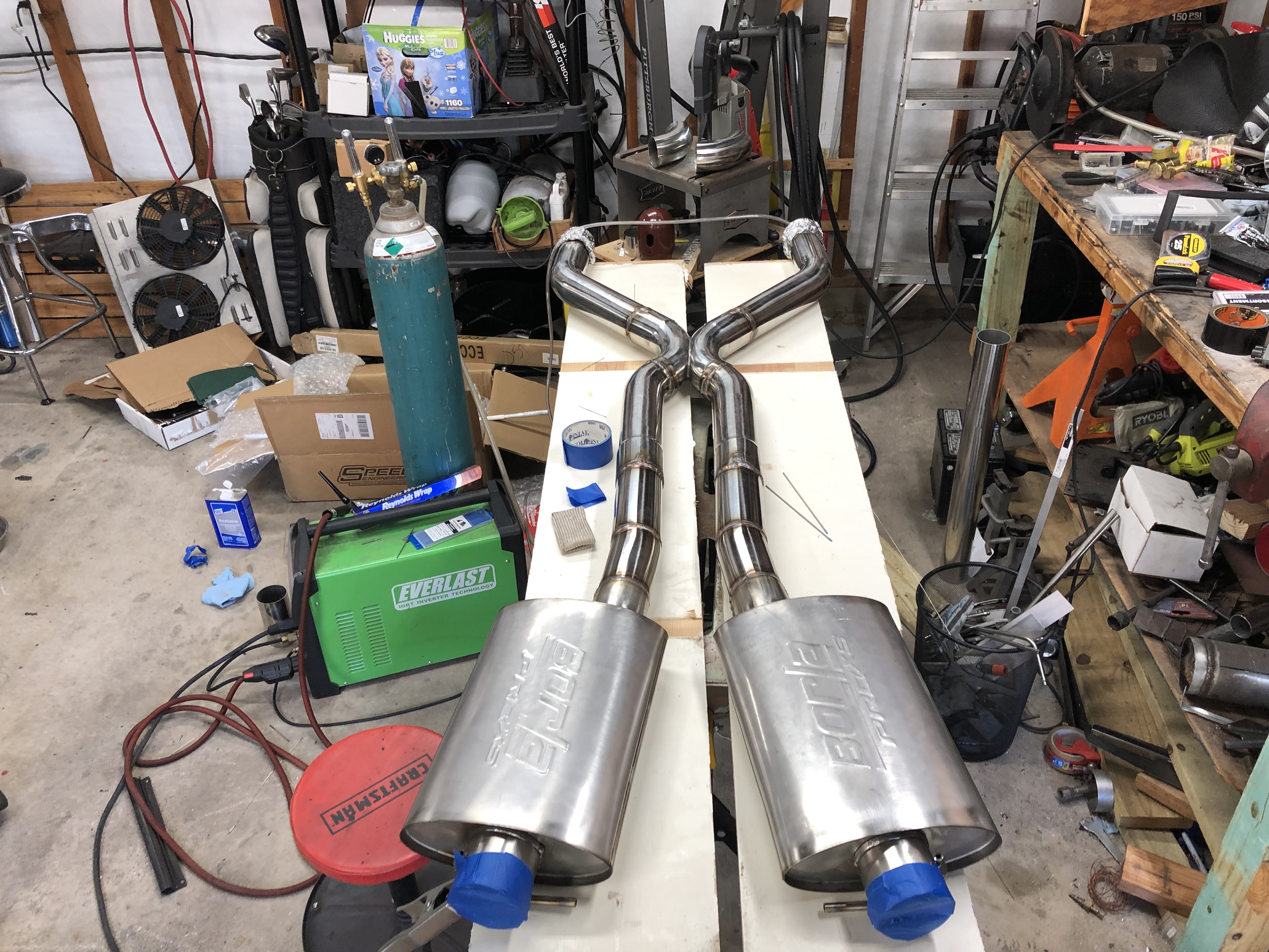
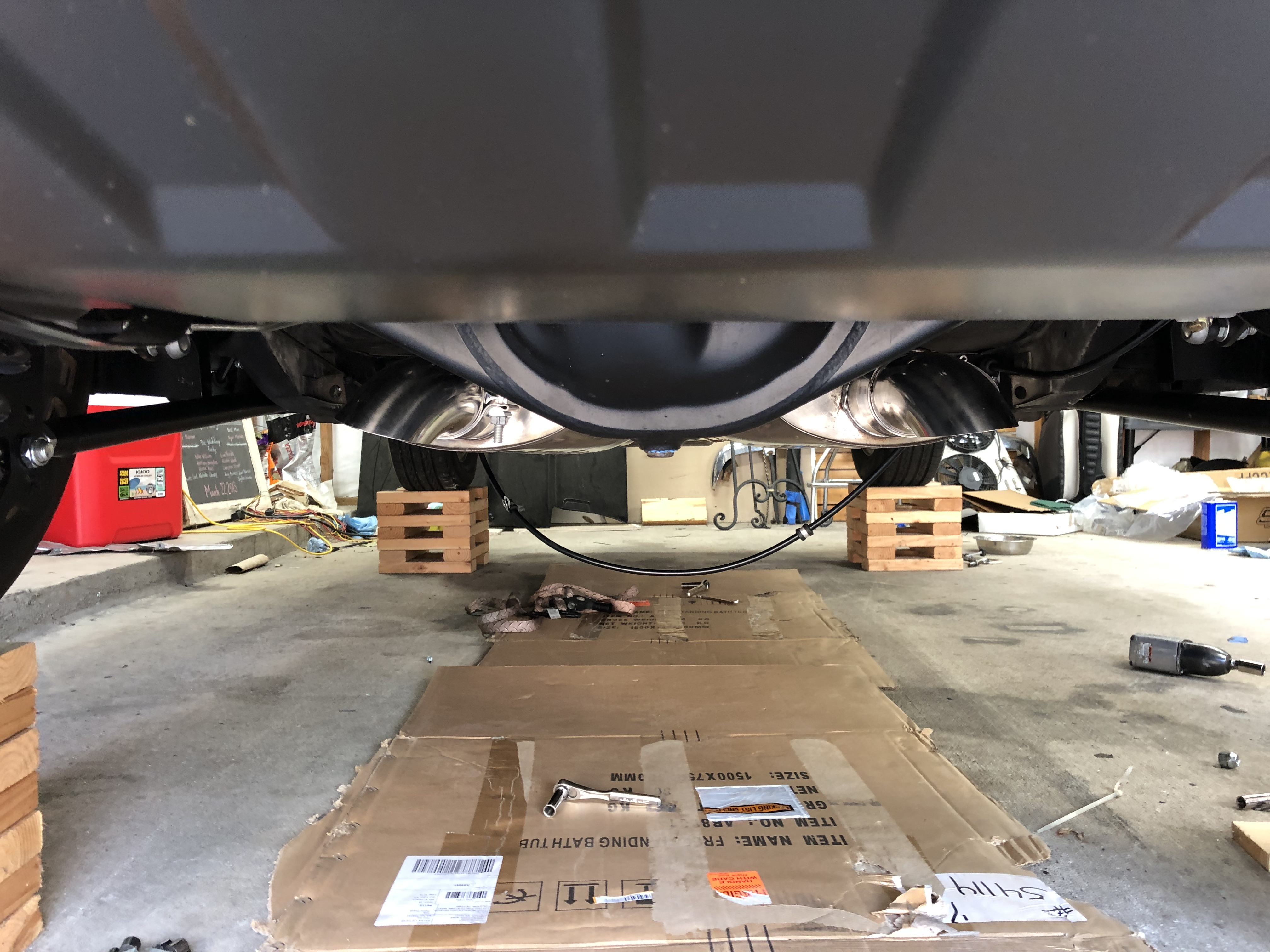
I shopped around for an exhaust system for a little while looking for a good system to fit the Ridtech rear and just couldnt find it. One way or another it would need to be adjusted to fit my needs with the rear and the headers. Price was another concern, the cheaper ones came in 409ss and I preferred getting a kit with 309ss if I was to spend over $600. I ended up buying a 3" 304ss builder kit from speed engineering and Borla PorXS mufflers, also 304ss. The total cost was $350 plus blood sweat and tears. It was a little time consuming TIG welding and back purging everything but it ended up turning out pretty nice, better than I thought actually. Nothing like building something yourself!
The builder kit came in slip fit and I opted for slip fit on the mufflers too, this made things a little easier for fitting. For the most part I had to stick it in place and clamp it, then weld it. I started bu hanging the mufflers and used some scrap .065" wall 3/8" ss tubing as the hangers, much cheaper and lighter if it matters than 3/8" solid $10 a piece ss bar hangers and they are surely capable of doing their job.
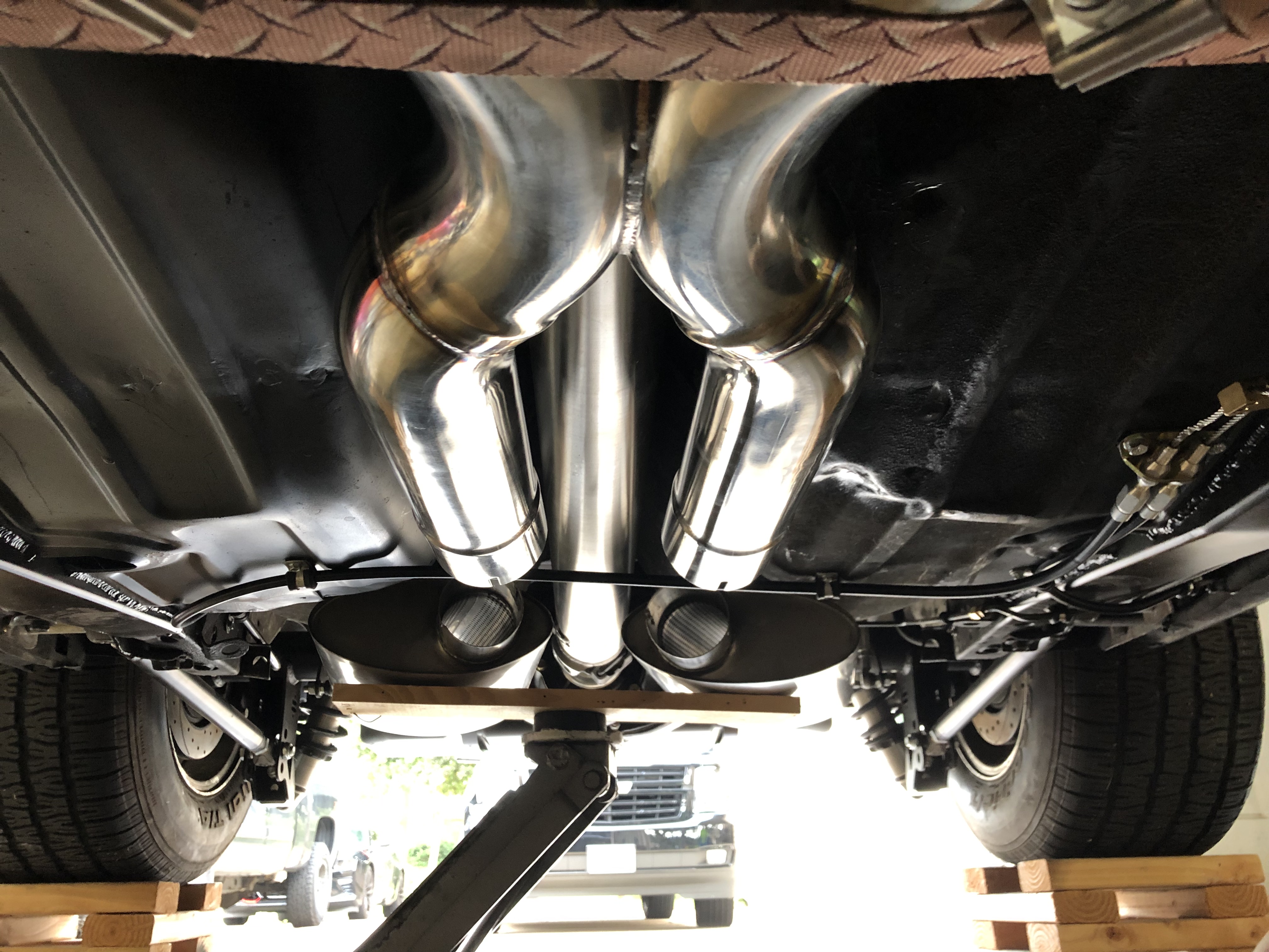
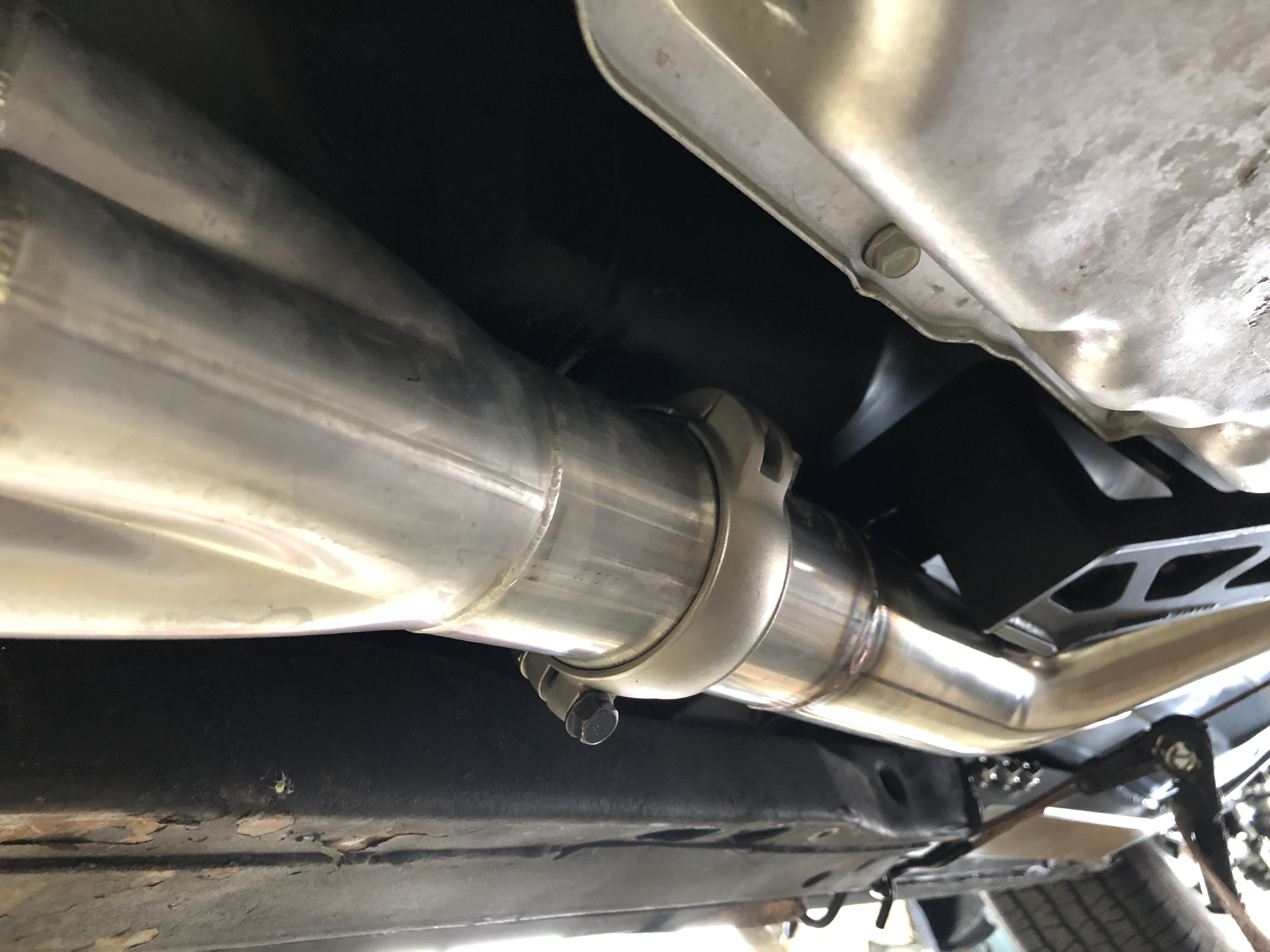
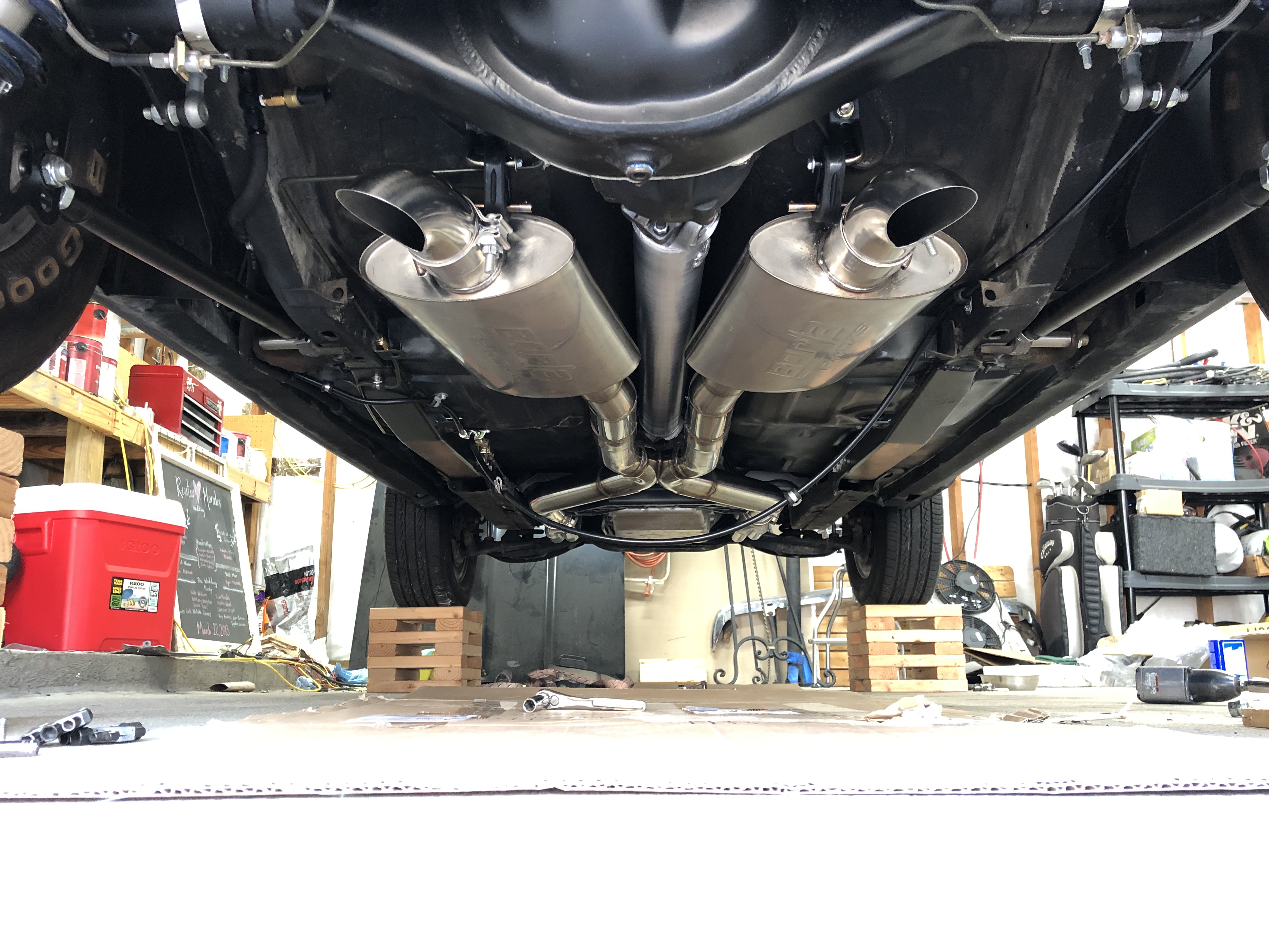
I first hung the header, got the angle right to ovoid hitting he rear center section. I then fitted the x-pipe front section to the headers and tacked my Ultimate Headers low profile flanges on. If any of you purchase these low profile flanges you need to get a good quality fastener. The one that came with it from Ultamate Headers is a nice ARP flanged SS bolt and a non-SS nut of lesser quality. The first attempt to tighten everything lead to the nut galling up on both clamps and I had to cut both of the nice ARP bolts to release the clamps. I ended up going to the hardware store and purchasing some matching Grade 8 fasteners and they worked out great taking them on and off a few times. Ultimate headers offered to send out replacements but I did not want to wait. After a lot of cutting and welding I was done, I added a little bit of tension to the to the rear hangers to keep the system nice and sturdy. Like I mentioned a while back, the PS header is tucked in real close and the crossmember did not line up good so I cut off about 1/8" of the crossmembers exhaust relief to make room rather than making more cuts and welds on the exhaust.
For now I dumped the exhaust before rear and it may stay like this forever or I might change it to go under the axle and exit out the rear if I don't like the sound.
09-20-2019 #27 Registered User
- Join Date
- Aug 2017
- Location
- SC
- Posts
- 48
That came out really nice.
Daniel
09-21-2019 #28
Registered User
- Join Date
- Jul 2017
- Posts
- 166
Thanks!
01-07-2020 #29
Registered User
- Join Date
- Jul 2017
- Posts
- 166
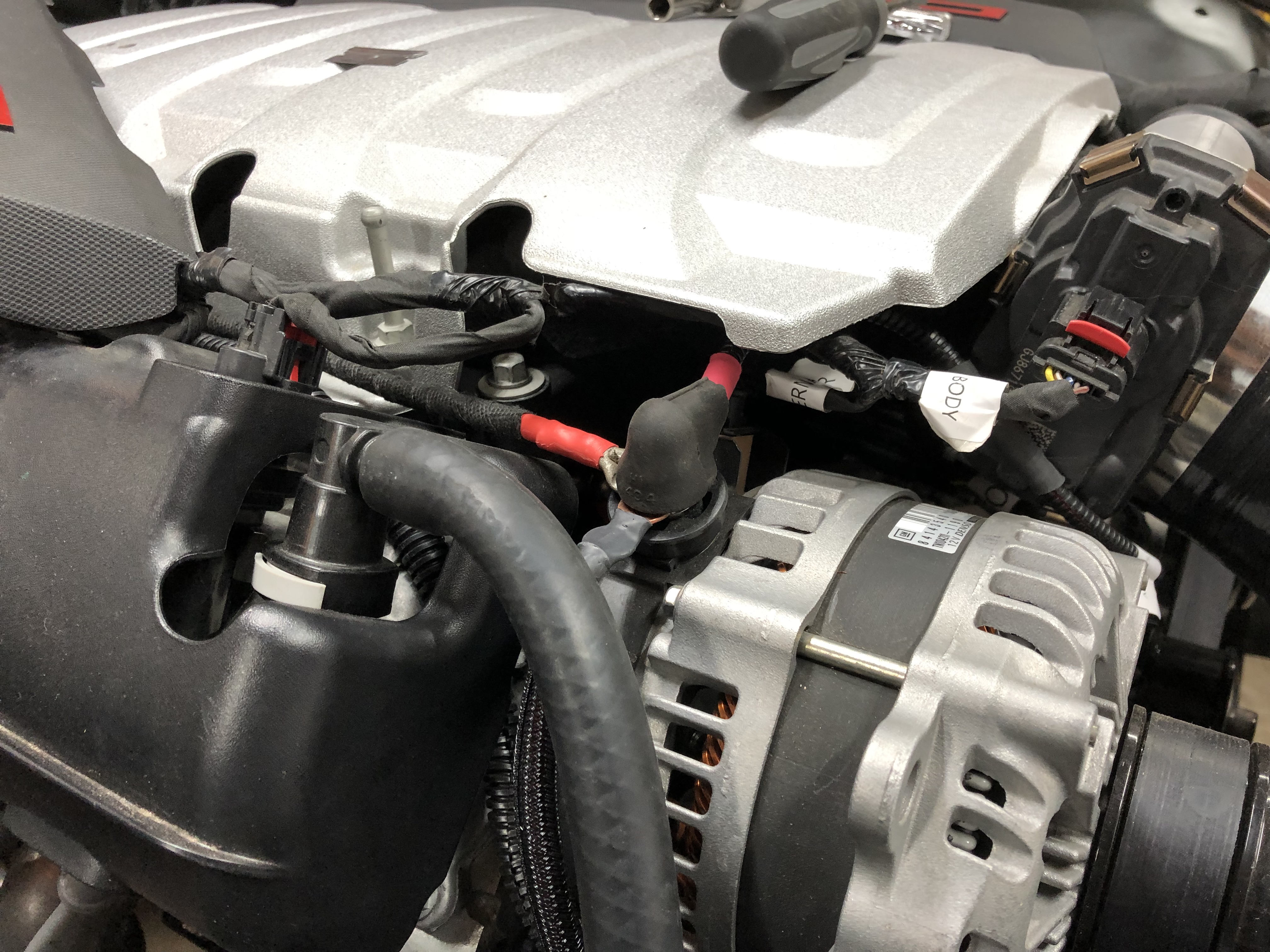
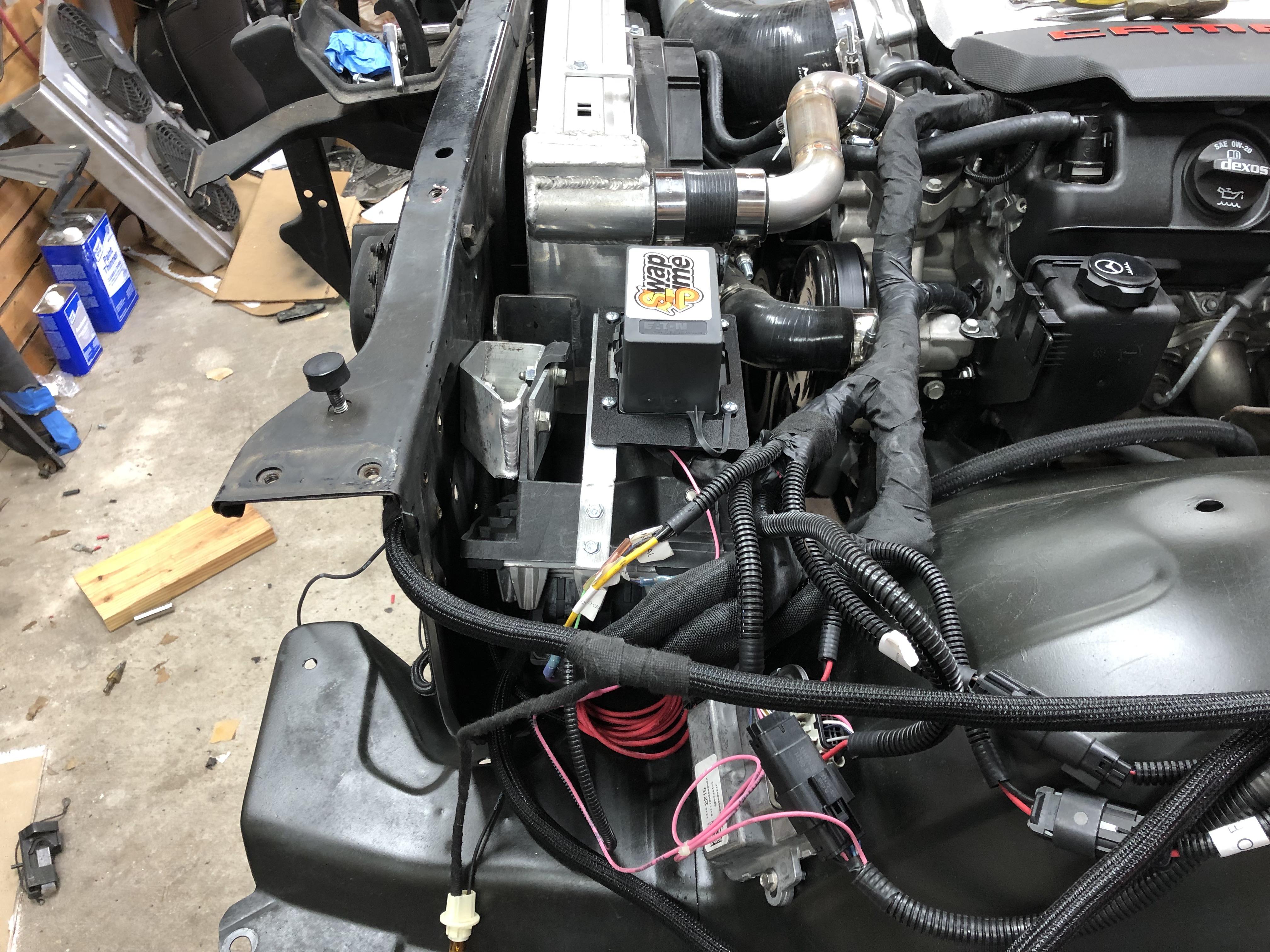
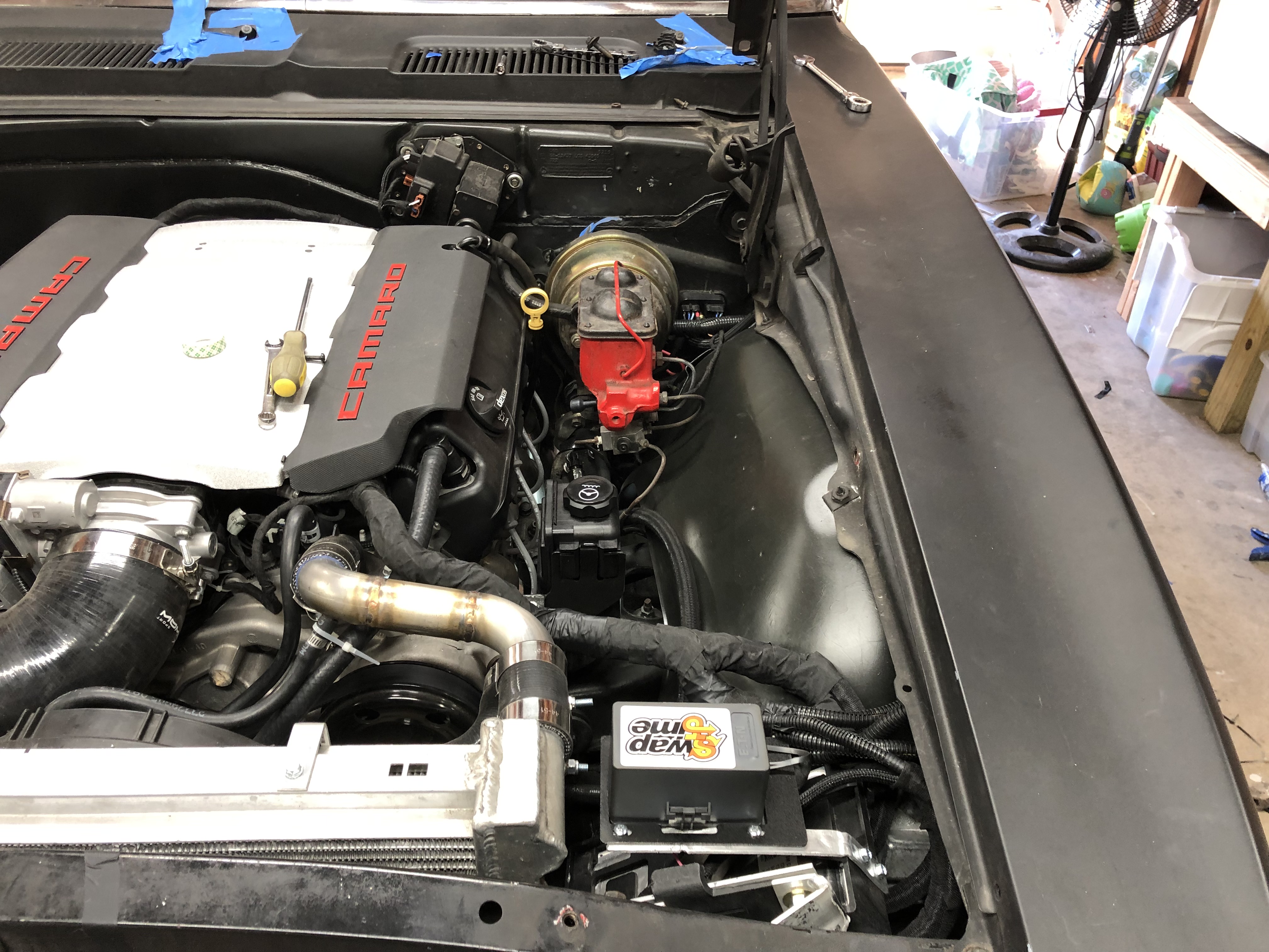
Its been a while but I got my engine harness and fan plug in so I started getting everything fitted. The harness looks good and functions as well. The harness is like others and just requires a battery power, ignition and crank wire to get going, all else is plug and play. It also has a brake signal it needs, not sure is others need this but its requred for me. For this I used my 3rd brake light wire for this as I do not have one and the AAW came with one. Here's some photos of the process.
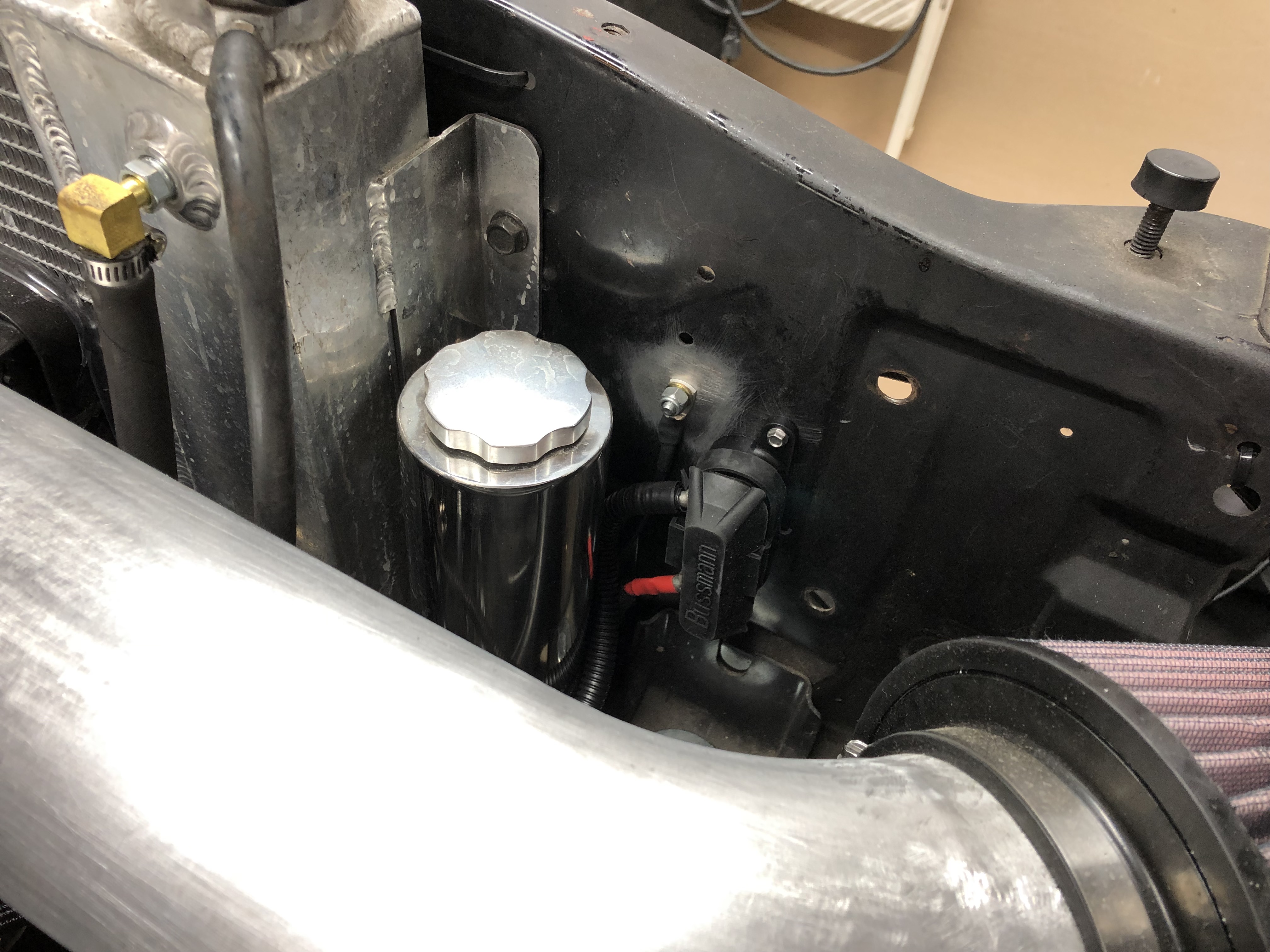
Wiring up the fan is easy, it has a PMW trigger wire, power and ground. The harness has the pwm wire labeled and you just have to crimp it and go. The harness builder recommended I add a fuse to protect the fan and I did so. The power is coming right off the alternator.
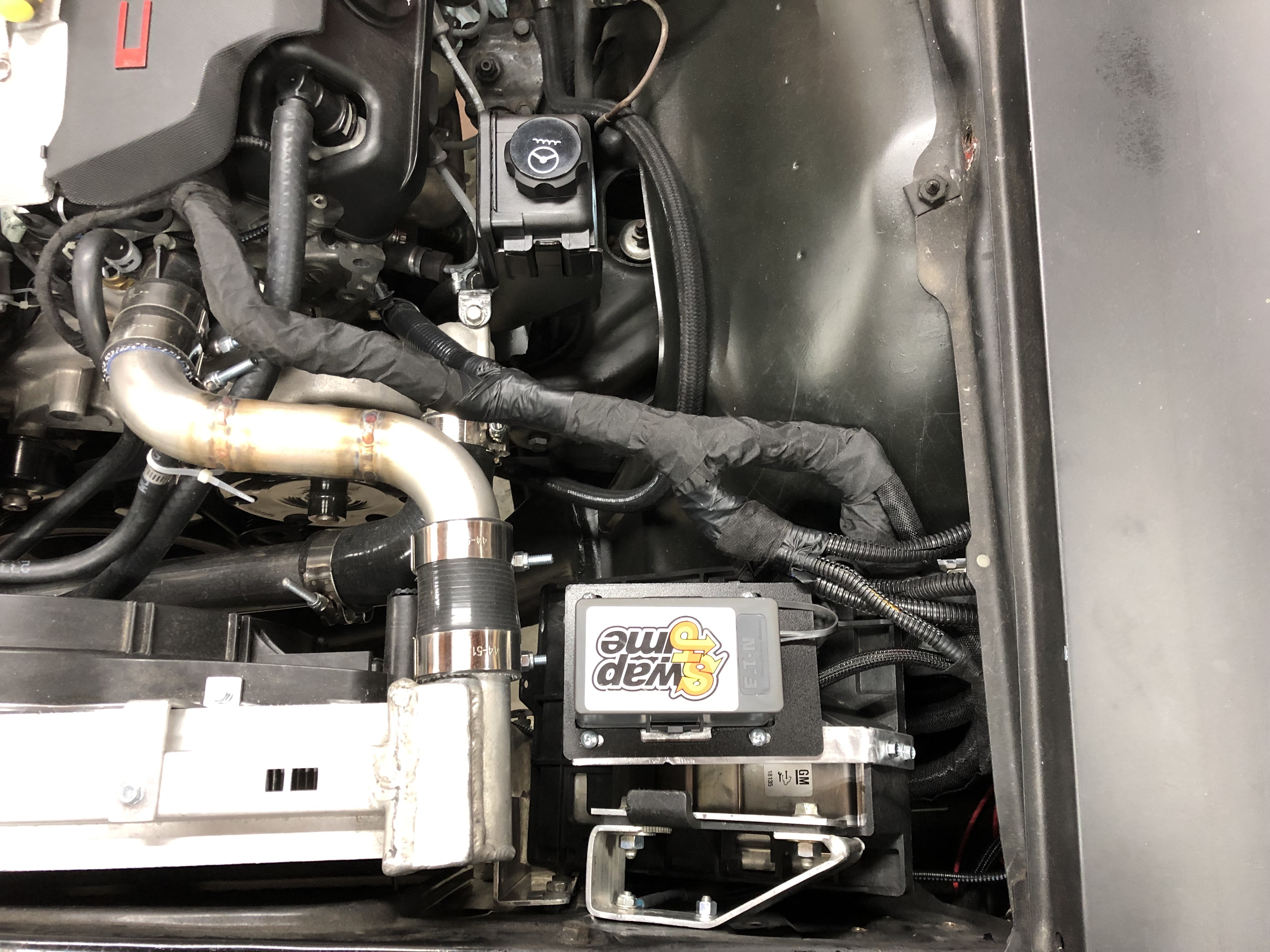
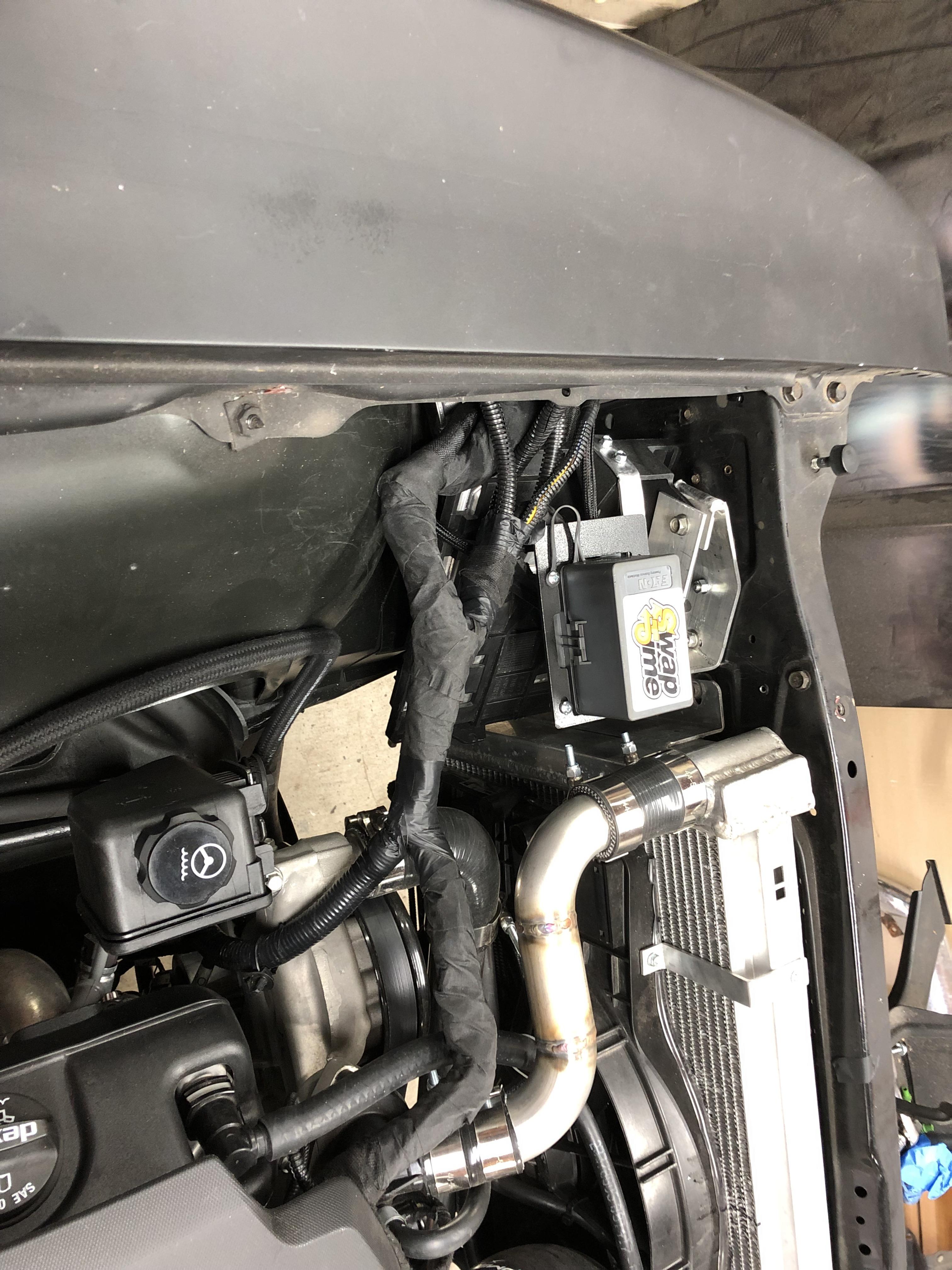
I removed the DS finder and ran all the wiring through there and hide them. The PWM fuel harness also traveled along the bottom of the car following the brake line to the low pressure sensor and fuel pump in the tank. The TCM is located on the DS side cowl and the ECM is mounted next to the radiator. The interior harness containing the OBDII port and pedal has been ran through the side cowl, the harness also includes a plug for the additional module for tapshift and what not but I do not have that yet.
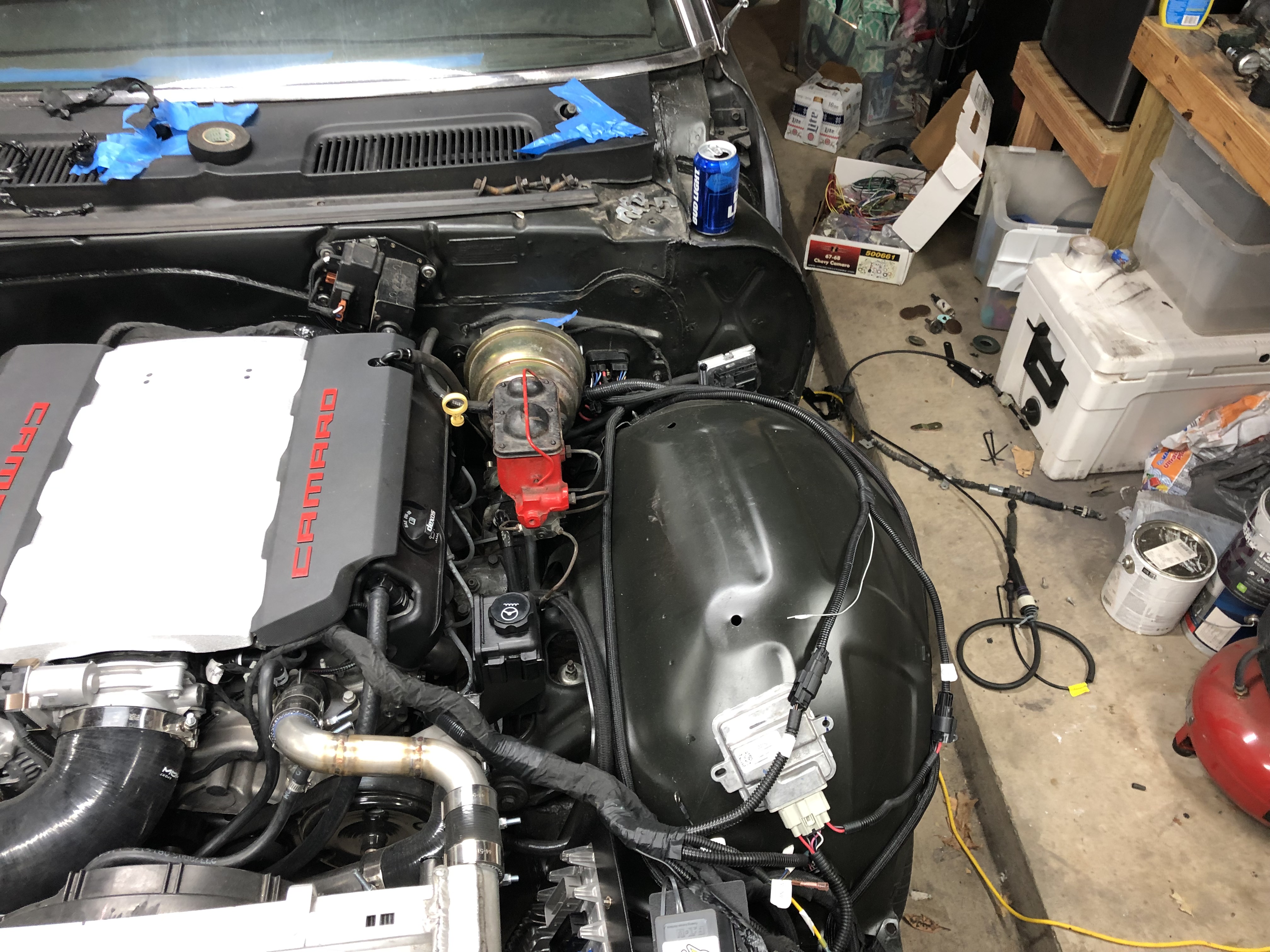
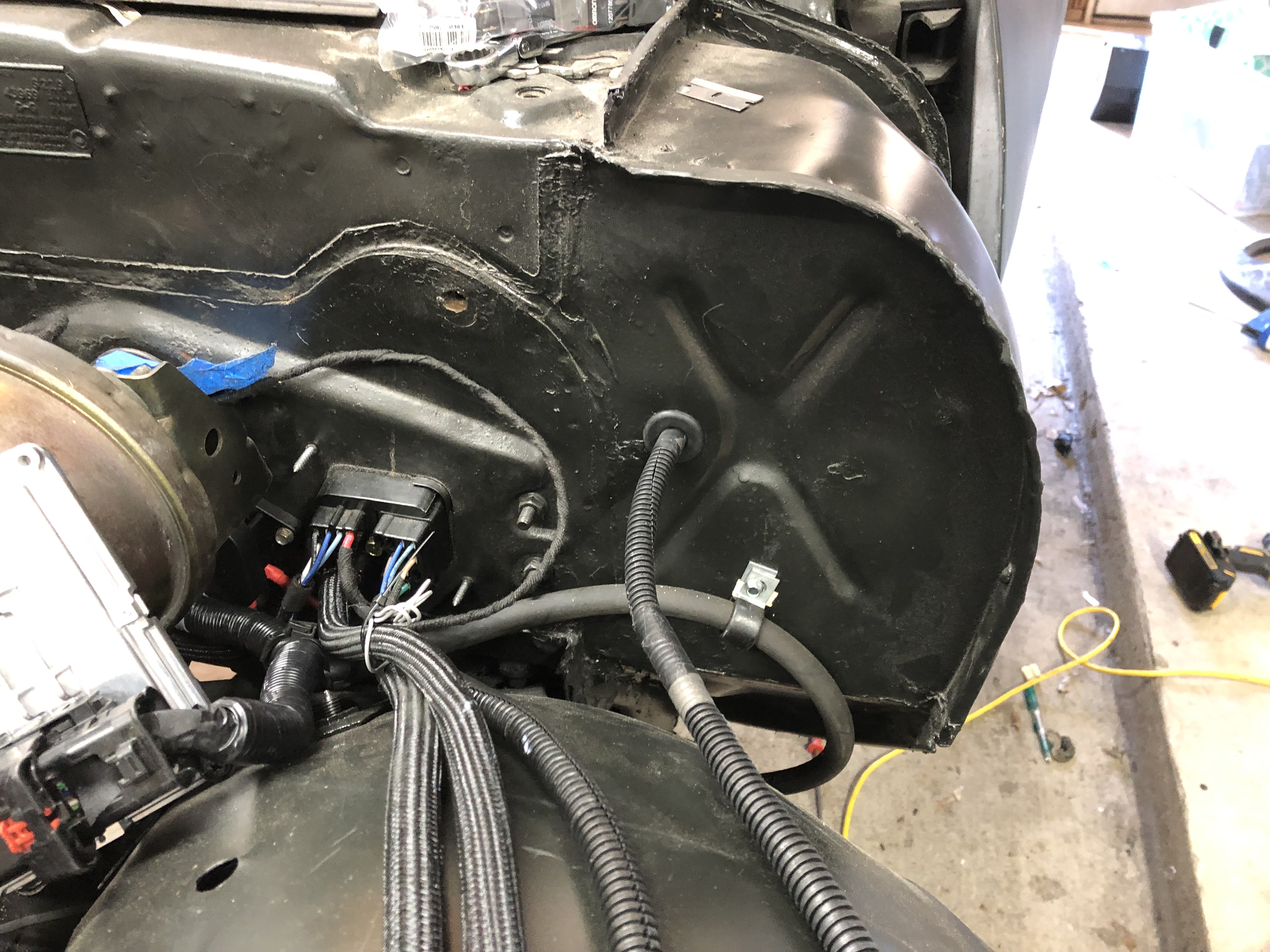
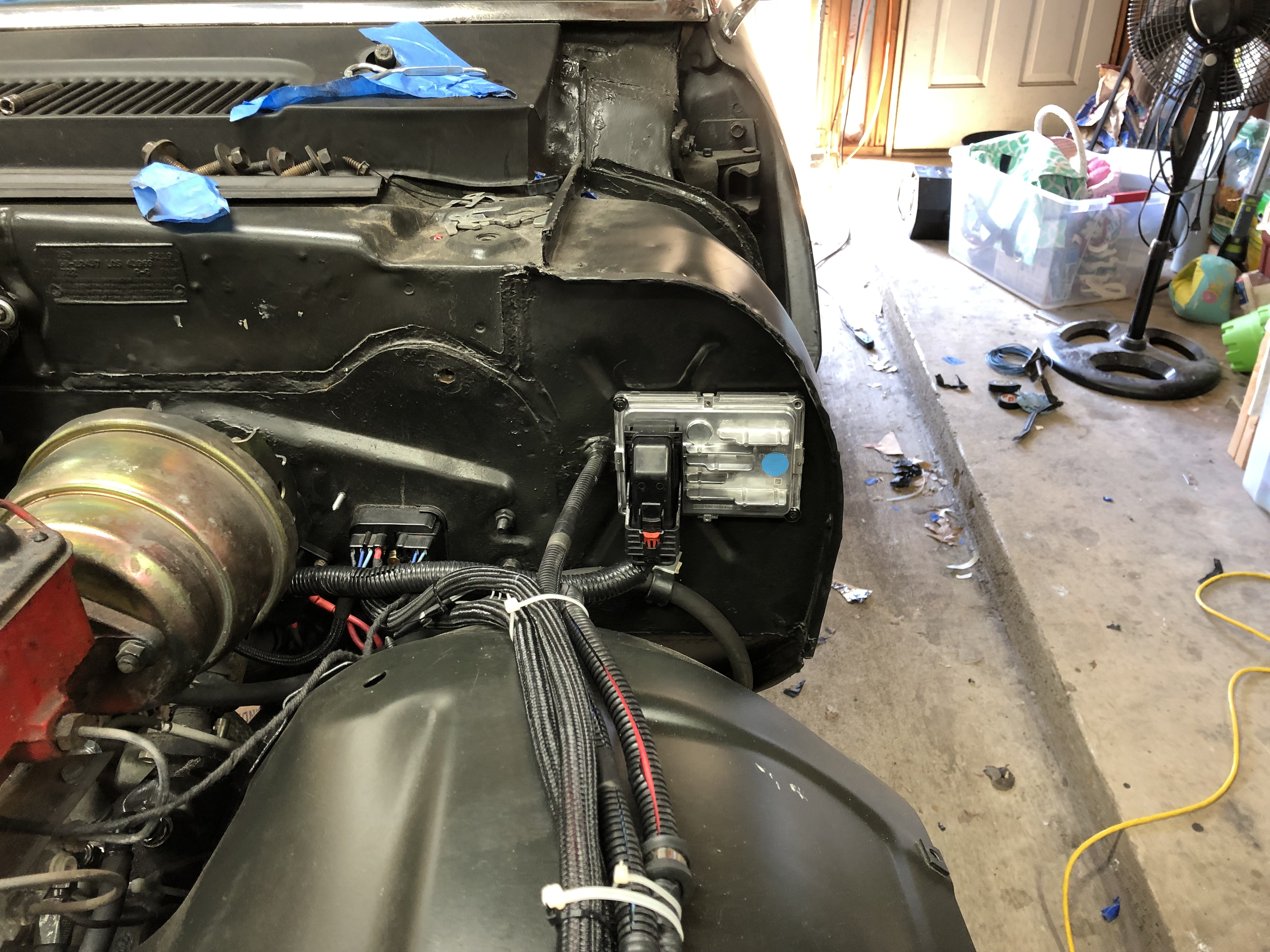
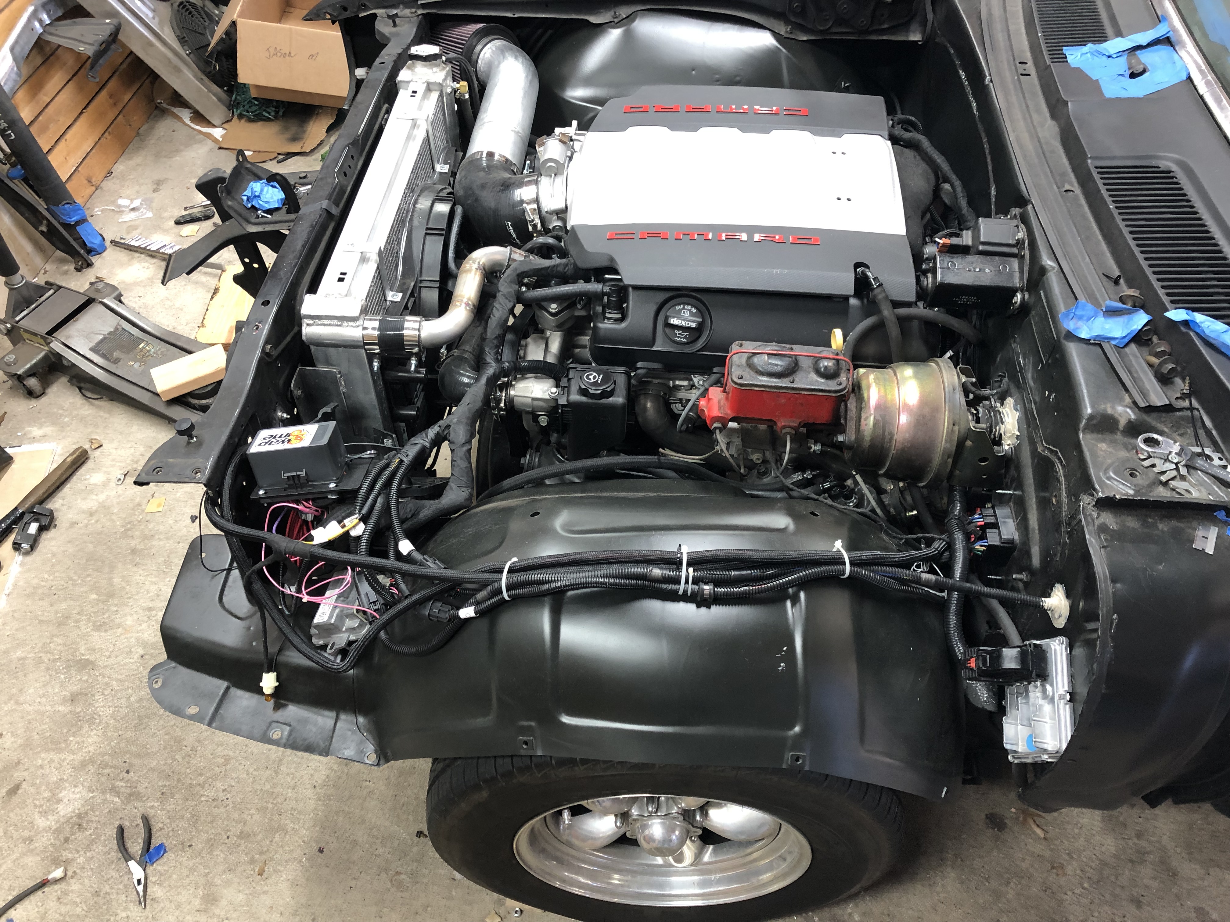
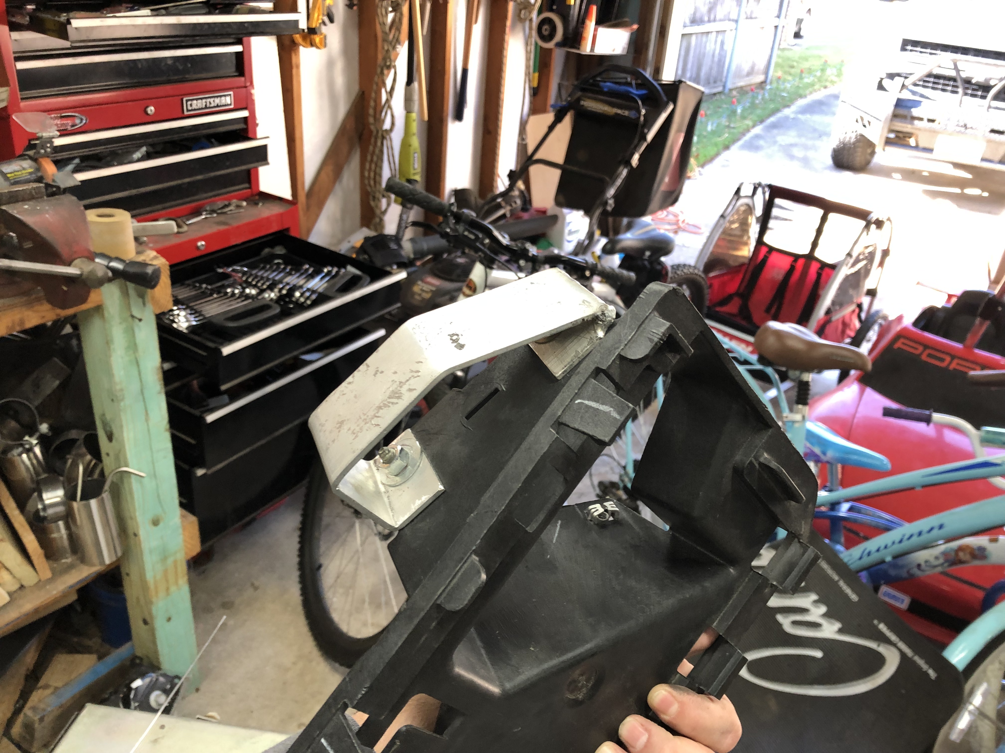
I created a couple of brackets to hold the ECM and fuse box using the factor ECM holder and some aluminum scrap I had laying around. Everything tucked in nicely in the corner of the engine bay and hidden behind the DS fender.
01-07-2020 #30 Registered User
- Join Date
- Jun 2017
- Location
- Idaho
- Posts
- 171

That brake input needs to be hooked up to a dual output brake switch. It needs +12v applied when the brake is released. It controls your TC lockup and needs to be de-energized when the brake is pressed. Opposite of brake lights.
01-07-2020 #31
Registered User
- Join Date
- Jul 2017
- Posts
- 166
Well according to the instructions is needs the opposite of what you are saying, maybe its wired differently. I'll get with the harness builder to confirm. Originally Posted by Snowcatter

https://www.swaptimeusa.com/download...tructions.html
01-07-2020 #32
Registered User
- Join Date
- Jun 2017
- Location
- Idaho
- Posts
- 171
If it is TCC input then it needs to be de-energized when brakes are applied. The TCC is torque converter control, when 12v is applied it locks the TC and needs to unlock when brakes are applied. If it needs opposite then it is not the TCC wire. I do LS swaps and this is important to be done correctly to keep your transmission happy. Definitely verify with your harness builder and good luck with your build.
01-07-2020 #33
Registered User
- Join Date
- Jul 2017
- Posts
- 166
how would the car act if it was wired incorrectly? I have drove it and it seems fine but there are some torque management issues in the tune and the throttle is only at 70% at WOT. Was at 60% but he sent me a new tune and it opened a little more, just trying to get it dialed in at this point. I believe 80% is where I want to be?
01-08-2020 #34
Registered User
- Join Date
- Jun 2017
- Location
- Idaho
- Posts
- 171
You actually won't notice much other than possibly odd shift points sometimes. Short trips won't show any symptoms, but your transmission will overheat due to TC not being locked up.
01-08-2020 #35
 Registered User
- Join Date
- Nov 2006
- Location
- Mountain Springs, Texas
- Posts
- 4,495
Don’t be so sure of that. Early LS are like that but not the later ones. Most are now the same as the brake light.... Originally Posted by Snowcatter
Here’s an example
https://docs.google.com/document/d/1...W51HIMEHc/edit
Bottom line is do your homework and listen to your harness/ECM supplier.
Don1969 Camaro - LSA 6L90E AME sub/IRS
1957 Buick Estate Wagon
1959 El Camino - Ironworks frame
1956 Cameo - full C5 suspension/drivetrain
1959 Apache Fleetside
01-08-2020 #36
Registered User
- Join Date
- Jun 2017
- Location
- Idaho
- Posts
- 171
That is good to know...2010 is the newest swap I have done with a standalone harness...be nice to know what year they changed the TCC control method. The 2013 I'm doing right now is a full factory ECM and harness with manual trans so no TCC. But all that aside my point here was to advise the OP to make sure on the TCC because he mentioned that he wasn't 100% sure on it. The harness builder is the only one who can give the final say. I am a member of a few LS swap groups and many people hook them up wrong.
01-08-2020 #37
Registered User
- Join Date
- Jul 2017
- Posts
- 166
Yeah, the instructions and his youtube videos all list the brake wire to be hooked up to a 12v source when brakes are applied. I did also checkout speartechs instructions and it wants 12v when depressed. It all must have to do with how the harness is wired. On another subject my AC request goes to a module that needs to see a negative signal and then shoots it out to a positive 12v after a relay so maybe he just wires it up how he feels is the best way to make it all work together. Originally Posted by Snowcatter
01-08-2020 #38
Registered User
- Join Date
- Jul 2017
- Posts
- 166
Started right up after I chased down an electrical problem. Turns out my Ford solenoid did not like being mounted to my plastic battery box and needed a ground.
01-10-2020 #39
Registered User
- Join Date
- Jul 2017
- Posts
- 166
Here's a video of the car doing a pull from around 45mph. The trans tune has the car shifting at a little over 5000rpm, not sure if thats what these transmissions want or if its just because its on a tahoe tune at the moment. There are a few kinks to work out in the tune. The throttle is only opening 70%, its a little rich in areas and timing needs some adjustment.
This thing sounds so cool shifting through all the gears and just keeps pulling. Cant wait to get it all dialed in and better tires.
Also, I never mentioned the shifter. Its a Lokar sport shifter. It has a low gear that allows the shifter to slide over and perform tapshift functions by pushing it forward or back.
01-10-2020 #40
Registered User
- Join Date
- Jul 2017
- Posts
- 166
Here's a video of the car doing a pull from around 45mph. The trans tune has the car shifting at a little over 5000rpm, not sure if thats what these transmissions want or if its just because its on a tahoe tune at the moment. There are a few kinks to work out in the tune. The throttle is only opening 70%, its a little rich in areas and timing needs some adjustment.
This thing sounds so cool shifting through all the gears and just keeps pulling. Cant wait to get it all dialed in and better tires.
Also, I never mentioned the shifter. Its a Lokar sport shifter. It has a low gear that allows the shifter to slide over and perform tapshift functions by pushing it forward or back.


 Reply With Quote


