

Results 161 to 180 of 527
-
02-25-2019 #161

 Registered User
- Join Date
- Oct 2018
- Location
- Phoenix, AZ
- Posts
- 584
 Thanks for the kudos! It means a lot.
 Originally Posted by cornfedbill

You are absolutely correct about the upper ball joint. I actually had to special order some low grade bolts with the correct 5/8-18 thread so I can do exactly what you suggested. They just haven't arrived yet. Hopefully I can get that done this week. We figured the clevis, being high carbon, would be too prone to cracking.'95 F-150 track ready street beastWant more projects/photos? Check my Instagram
-
03-02-2019 #162
Registered User
- Join Date
- Oct 2018
- Location
- Phoenix, AZ
- Posts
- 584
OK suspension experts weight in on this one. I am out working on motor mounts and needed a break from crawling around so I decided to check some suspension measurements.
Over the course of 3" of travel in the front:
Gained 2.5 degrees of negative camber
Lost .5 degrees of caster...yes lost.
Here is my main question after thinking this through, camber gain seems aggressive, but I don't think it will be bad since there will likely be some body roll, am I wrong? For the caster loss I was bummed at first, but the more I think about it, isn't that actually helpful in something like autox? Wouldn't that make turning a little easier when you dive in hard on a 90 degree turn without killing high speed stability?
Let's bench race a little here boys. GO!'95 F-150 track ready street beastWant more projects/photos? Check my Instagram
03-03-2019 #163 Registered User
- Join Date
- Aug 2012
- Location
- Peoria, AZ
- Posts
- 1,758
How much caster did you start with before loosing .5?
I'll try to find my alignment specs from the last time I had mine on a rack with a pull down setup. I dont remember if it list caster or not but I was paying more attention to bump steer and camber gain under compression...not caster.Lance
1985 Monte Carlo SS Street Car
03-03-2019 #164
Registered User
- Join Date
- Oct 2018
- Location
- Phoenix, AZ
- Posts
- 584
I has 6 degrees at ride height.
'95 F-150 track ready street beastWant more projects/photos? Check my Instagram
03-04-2019 #165 Registered User
- Join Date
- Mar 2018
- Location
- la mesa, CA
- Posts
- 237
Wish I understood this stuff better than I do.
Guess where this thread was posted?
03-04-2019 #166
Registered User
- Join Date
- Oct 2018
- Location
- Phoenix, AZ
- Posts
- 584
Me too man. That's why I keep asking this stuff. More of this is slightly educated guessing than I'd like to admit. I Google the topic to death and then just get to cutting. Too few truck projects out there and basically none are sharing real data and setup figures. That's one of my big goals with this. I'll share everything in the hope it helps others working on oddball vehicles too. Originally Posted by Project Bike Truck
'95 F-150 track ready street beastWant more projects/photos? Check my Instagram
03-04-2019 #167
Registered User
- Join Date
- Aug 2012
- Location
- Peoria, AZ
- Posts
- 1,758
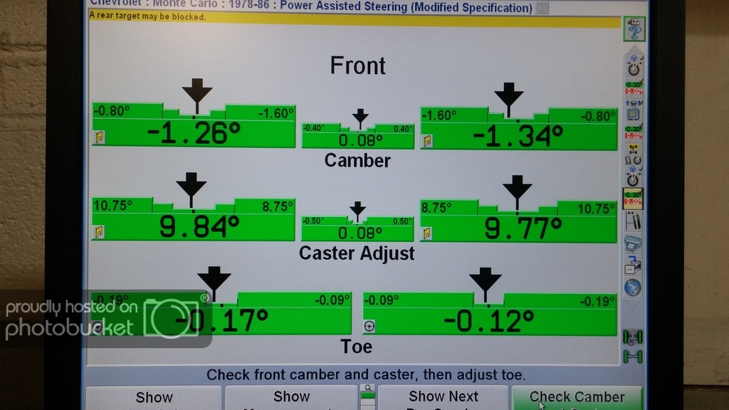
Let's see if I can get photobucket to place nice here...
These were taken the last time my car was on an actual alignment rack, 3 years ago I believe.
This was at ride height after adjustments...
And this was with the front suspension compressed about 1.5" at the shock if I recall correctly.
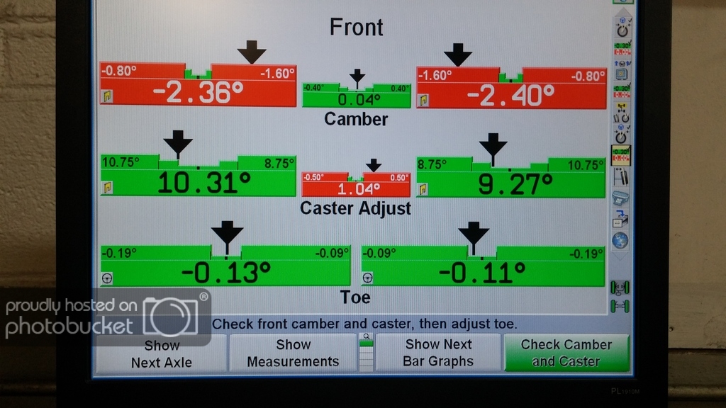
Looks like we may not have pulled the front down exactly square (pulled one side down more than the other) and if I also remember right, we had issues with the caster moving the turn plate so much that it was interfering with the lift ramp itself. That said, I'd bet pretty good money that the caster stayed close to the same as the camber gained about 1 degree in that 1.5" of travel at the shock.Lance
1985 Monte Carlo SS Street Car
03-04-2019 #168
Registered User
- Join Date
- Oct 2018
- Location
- Phoenix, AZ
- Posts
- 584
Thanks for sharing this Lance!
So it seems like I'm a bit low on my caster setting initially and my camber gain is slightly more aggressive?
Darn....now I'm wondering if I need to move and revise my upper control arm mounts.'95 F-150 track ready street beastWant more projects/photos? Check my Instagram
03-04-2019 #169
Registered User
- Join Date
- Aug 2014
- Posts
- 435
Did you have this moved from the Trucks section? Probably get a lot more attention over here.
03-05-2019 #170
Registered User
- Join Date
- Aug 2012
- Location
- Peoria, AZ
- Posts
- 1,758
So here is my thought on alignment\geometry opinions on what works best...they are like butt holes, everyone has one. :D
What I have picked up and learned over the years is that you need different geometry to accomplish different goals and it is all based on the equipment you currently have. For example, our goal was to get as much caster as well could on my car to correct the contact patch for the high SAI of the spindles and the amount of body roll my car had. The goal was to keep the outside front tire from going positive camber as you add steering angle and to get the inside front tire to lean into the corner instead of out. We accomplished great front grip with this method, really really great grip.
The only downside to running huge caster is the jacking effect of the front end when steering angle is induced...and this is a factor. It is multiplied by a few things, tire width and scrub radius mainly. With my smallish 275 front tires and a decent scrub, the jacking didn't have that much of an effect on overall handling...the added grip was well worth the side effect.
That said...since then I have added a ton of Ackerman with the new ATS Spindle steering arms and a lot less body roll with the huge front sway bar...and I am considering trying to take some caster out of the setup now to reduce the jacking effect...just to see what it does. Both of the changes above greatly increased the front grip..mainly from the inside front tire and my thought is that it may be a bit better overall without the jacking effect of the huge caster #.
See what I mean? All of it has to work together, there isn't a magical # to any one part of this. I just posted the results above because I was curious how much caster I gained or lost in compression as I'd never paid attention to that before. Hope this helps...Lance
1985 Monte Carlo SS Street Car
03-05-2019 #171
Registered User
- Join Date
- Oct 2018
- Location
- Phoenix, AZ
- Posts
- 584
That does help a bit Lance. I appreciate you breaking that down further. I thought that 10 degrees seemed a little extreme for caster.
I may just run with mine set as it is. I can definitely add or subtract any setting I want on the front suspension. That's the reason I went with the setup that I built. I do have to move the lower rear of the control arm to make room at full lock (geez the s197 has some good angle) and I might redo the upper control arm mounts to get rid of the caster change.'95 F-150 track ready street beastWant more projects/photos? Check my Instagram
03-05-2019 #172
Registered User
- Join Date
- Oct 2018
- Location
- Phoenix, AZ
- Posts
- 584
OK suspension theory aside for a minute (we will return to that after this update), I got the more pressing matter of frame boxing and engine/trans mounts going this past weekend.
I was both excited and nervous to get these started. I knew the frame being straight as a winding road would make boxing....interesting. On top of that I wanted to make sure the driveline angle matched the irs while being as low as I could safely and physically go.
First up after the initial test fit was to notch my front cross member. Nothing quite like cutting a chunk out of a day's work.
This is after an inch notch so I could lower the entire engine/trans package. It kept just hitting the floor of the cab when I was matching the pinion angles and I'm really trying to avoid a bunch of sheet metal work this time. In a perfect world I would have moved the entire oil pan behind the cross member (5 inches back) and lowered it another 2-3 inches down. I then remembered that I've already gone wayyyyyyy further with this project than I ever intended and doing more setback meant all new sheet metal behind the engine bulge of the firewall. No thank you. Every cylinder is behind the front axle. I'm calling this good. You can already see how much I've had to modify the firewall for valve cover clearance.
So the inch worked and now I needed to prep the frame to have mounts and braces welded to it. My AWESOME neighbor (seriously my neighbors are better than yours) cut me strips of "scrap" 3/16 steel plate to box the frame. But I wanted to add in some internal support behind the plate around where the trans would mount (or so I thought).
You may notice the cab is like RIGHT THERE. Yeah...my dumbass crawled under this thing to cut, trim, and weld this portion. Not fun even at 28. Then it finally clicked that I needed to remove the cab anyway. Duh.
And then it was much easier. Also, check out that cab moving system. Yeah that's bricks and furniture dollies. It worked pretty well to just roll back and gave basically all the room I needed to do this center section of frame. One day I'll have a real shop of my own with help. This was solo.
With a good foundation to mount everything I tacked those Ruff Stuff motor mounts I've had hidden in a box. Little pricey, but man they are nice. VERY easy to mount and align. I'd recommend these to anyone with a SBF that likes this poly mount all the LS swaps use.
Then I shimmed everything to match my 3 degrees of pinion angle and leveled the motor. Suddenly I realized those tubes I added to mount the rear of the lower control arms were the perfect base for my motor mount stand offs.
Ta da! And no header interference for once. I'll add a little bracing to these just to tie everything together.
This also gave me a reason to bust out my new notcher from Rogue Fab that I got with my bender. If you're in the market, get this one. I've used many and this is the best I've touched so far. Ignore my cramped work space.
Then I started on the trans mount. I thought I would go to the plating on the frame rails. So here is V1.
Not a fan. Its long and would need loops for the exhaust. Just didn't seem like the right move. I don't have enough tubing yet, but those poly mounts will be moved to mount on the chassis "X" that I'm doing next. Then I'll have more exhaust space and it will all tie together better.
This push allowed me to return the pan and head I borrowed from the engine builder. He is working on knocking my build out over the next couple weeks.
So now I need you guys to weigh in. I'm going to have to wire this beast from scratch. I know that I want it to all be the new solid state stuff. So think PDU, PDM, etc. I can't decide which one. Mainly because of the switches each is compatible with. So far I'm looking at:
Rywire PDM
ECU Master PDU
Racepak Smartwire Streetwire
Cartek PDM16
All of these are expensive for me and additional switches make it worse, but the whole truck will run through this except A/C and window motors. I don't like wiring failures and the ease of use combined with the reliability is hard to ignore. Weigh in your thoughts or experiences. Any vendors wanna help a brother out a little for some fender space?'95 F-150 track ready street beastWant more projects/photos? Check my Instagram
03-06-2019 #173
Registered User
- Join Date
- Jan 2016
- Location
- Chino Valley, AZ
- Posts
- 134
I have zero input on what wiring system is best, but I would consider how you're running the wiring before continuing on with boxing the frame. You might want to consider running wiring/brake line/etc down the inside of the frame for a clean look.
03-06-2019 #174 Registered User
- Join Date
- Nov 2016
- Location
- Sulphur, La
- Posts
- 599
I like that notcher. Mine can't notch close to a bend like that one can.
03-06-2019 #175
Registered User
- Join Date
- Oct 2018
- Location
- Phoenix, AZ
- Posts
- 584
Great point. I think I'm going to run the wires along the outside of the passenger frame rail and fuel/brakes along the driver's side. Something about that much wiring being hidden bothers me thinking about if I ever had to open the loom or add something. And I don't like hoses to be hidden since you can't see leaks that way. Luckily this is a "fair weather" toy. I'm all about function over form and I plan to beat this truck pretty good when it's done so I expect to need to service and replace components that most people never think of. Plus how do people secure hoses inside frame rails after it's all welded? You couldn't weld with that stuff already installed.
- - - Updated - - -
It can actually notch on a bend. Its seriously impressive and they make everything right here in the US. Originally Posted by CSG
'95 F-150 track ready street beastWant more projects/photos? Check my Instagram
03-07-2019 #176
Registered User
- Join Date
- Sep 2013
- Location
- sw Kansas
- Posts
- 1,643
I'm late to the party. In case you don't know, the Mustang rear doesn't have a centered pinion. You haven't mentioned how you are going to brace the front chassis around your suspension. The truck frames aren't capable of sustaining twist without substantial crossmembers. There is a reason most of the aftermarket crossmembers have 2 x 4 tubing bent for the center brace. If you have access to someone with finite analysis, you might consider some stress calculations. I'm sure you want to be safe.

03-08-2019 #177
Registered User
- Join Date
- Oct 2018
- Location
- Phoenix, AZ
- Posts
- 584
I would actually say you are right on time to the party. I did notice the off center pinion, but didn't think it would cause me any issues. Please let me know if I'm wrong about that. I am absolutely planning on doing chassis bracing. I am starting that by boxing the entire frame between the front and rear suspension. Then I am picking up more tubing tomorrow that will form a giant "X" in the middle. I'll add a number of smaller tie-ins beyond that. I wish I knew someone with finite analysis, but I haven't made any of those friends yet.
'95 F-150 track ready street beastWant more projects/photos? Check my Instagram
03-08-2019 #178
Registered User
- Join Date
- Sep 2013
- Location
- sw Kansas
- Posts
- 1,643
U-joints only compensate for one direction of misalignment. You will hear people tell you what they got away with very often. You are starting with a clean slate so it makes sense to me to do it the best it can be the 1st time. There are many very good websites detailing u joint angles. This is just one: http://www.driveshaftshop.com/angle-calibration. If you watch this video, it will show you better than I ever could try to explain: https://youtu.be/jaaTyL099RA . Boxing the frame will be a good step but a brace in front of your front suspension mounting points could be beneficial. The most advantageous point is in the middle where the engine sits. That's why most crossmembers are very substantial. In your area, you have Industrial Chassis. I believe the owner's name is Steve. He is very knowledgeable about suspension. It might be worth your time to visit with him and see if he has advice. Good luck and be patient.
03-08-2019 #179
Registered User
- Join Date
- Oct 2018
- Location
- Phoenix, AZ
- Posts
- 584
That video was a fantastic representation of what people always try and say with words. Thanks for sharing! Luckily my input and output shafts run parallel so they will "cancel each other out."
'95 F-150 track ready street beastWant more projects/photos? Check my Instagram
03-11-2019 #180 Registered User
- Join Date
- Mar 2014
- Location
- Yuma, AZ
- Posts
- 635
You could always run a CV driveshaft as well. Several people on this forum have used them with good results. That makes a lot of the drive line angles irrelevant.
Nelson
1969 Chevelle "Cone Smasher" Family Project
https://www.pro-touring.com/threads/...uot?highlight=
1984 "Rustang" GT, 5.0, 5 Speed Project
https://www.pro-touring.com/threads/...T-(Slow-Build)
Tags for this Thread

 Reply With Quote


