

Results 1 to 20 of 33
-
06-27-2018 #1

 Registered User
- Join Date
- Mar 2011
- Location
- Portland OR
- Posts
- 26
72 Nova With C5 Front/Rear Suspension
Hi,
This build will chronicle the build of my 72 nova. I have this thread going on a couple other forums, but I see a couple similar builds here, so I thought it would be nice to swap notes.
Aboutfour11 years ago, I happened across a corvette chassis/engine/transaxle drop-out on eBay... and that got the gears going in my head.
Pretty much since that day, I've been planning this project. Saving money... not to buy the parts, but to buy a house with a good sized shop. With the house found, I finished out the shop, and got ready for this project.
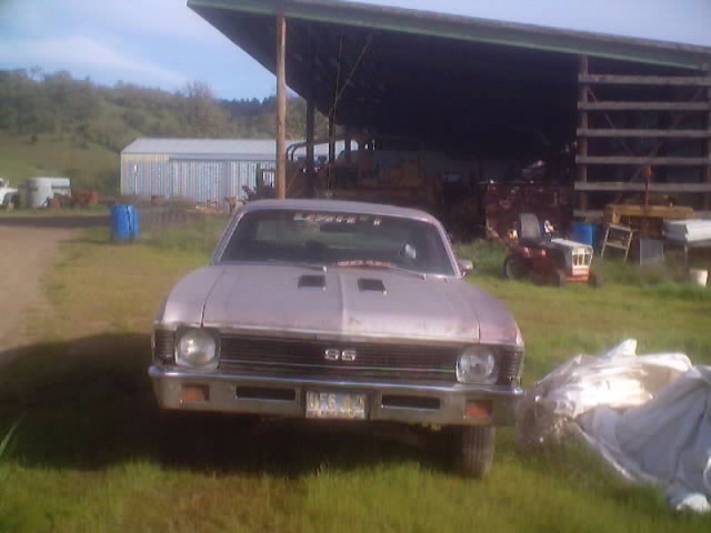
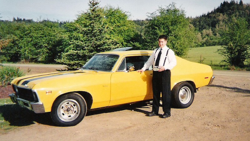
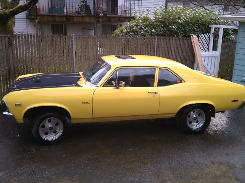
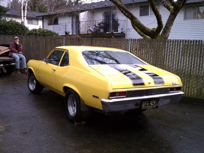
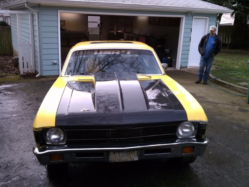
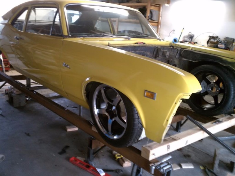
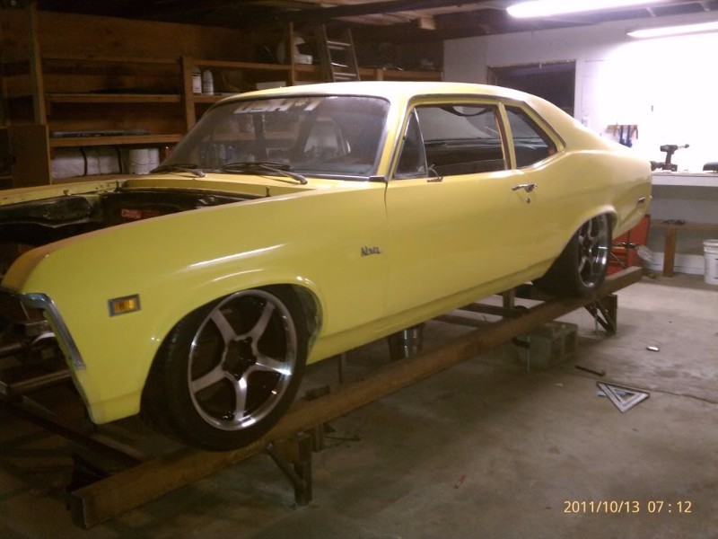
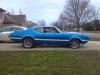
Anyway, I've owned this car since I was 15, in 2003, when it looked like this:

I painted it before I turned 16. Did all the body work, panel replacement, primer, and final paint. Had a professional help me mask the racing stripes. I was such a fresh faced young man for my first prom!
As high school came to an end, and college began, the poor old nova began to see neglect. I couldn't afford to drive it, so it got parked, and the motor was eventually pulled and used in a circle track car. And there it sat.
As the car sat, covered in dust... I looked at corvette chassis on eBay, thought about wheel choices, engine combos. All the while saving, saving saving. I needed a place to do this project. And eventually, the perfect piece of property came along. It had a 32x24 shop. It was also cheap, well located. minutes from work, minutes from downtown Portland, and it also had some kind of house or something, which turned out to be pretty nice as well.
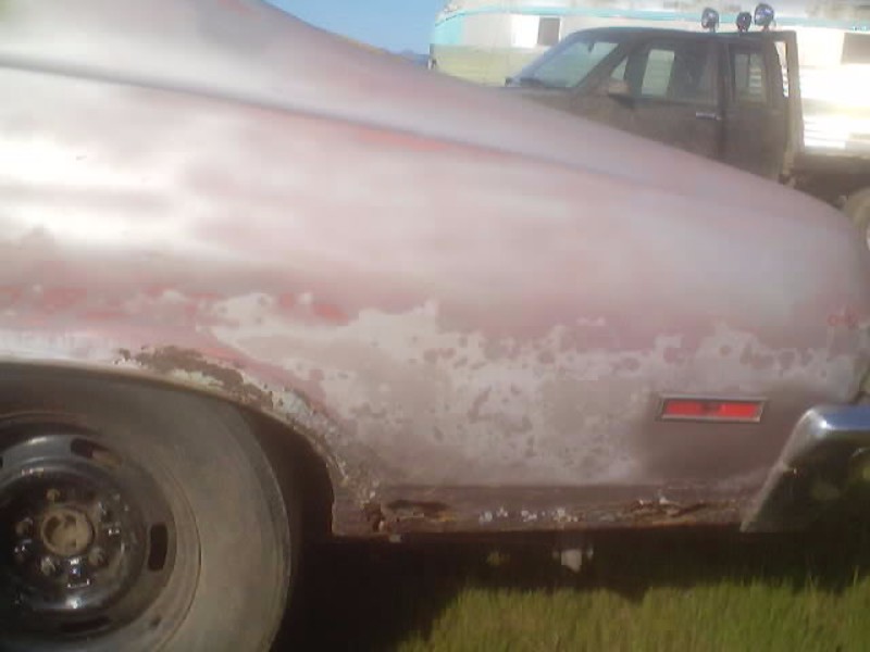
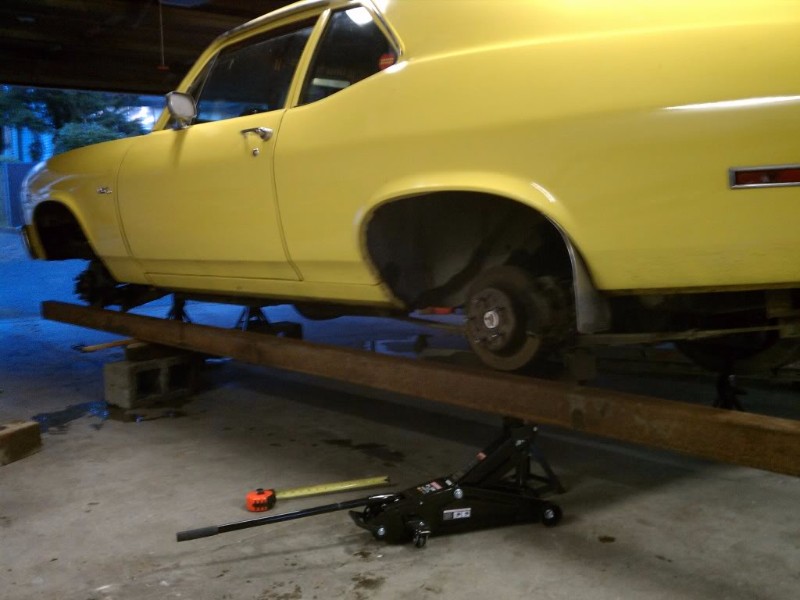
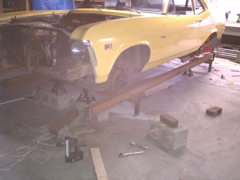
After re-wiring the house and shop, and getting my quarterly bonus and huge tax return, I was finally financially and schedule ready to begin this project. First step, dragging the old nova out of the hay barn in Roseburg Oregon up to Portland. My dad and brother get big props here for hauling the car up for me. Even after sitting all that time, it cleaned up nice!
March 2011
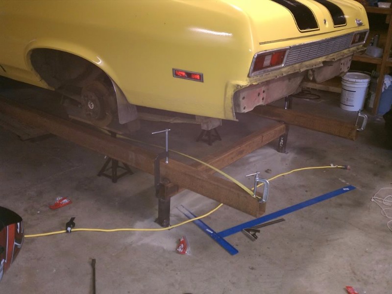
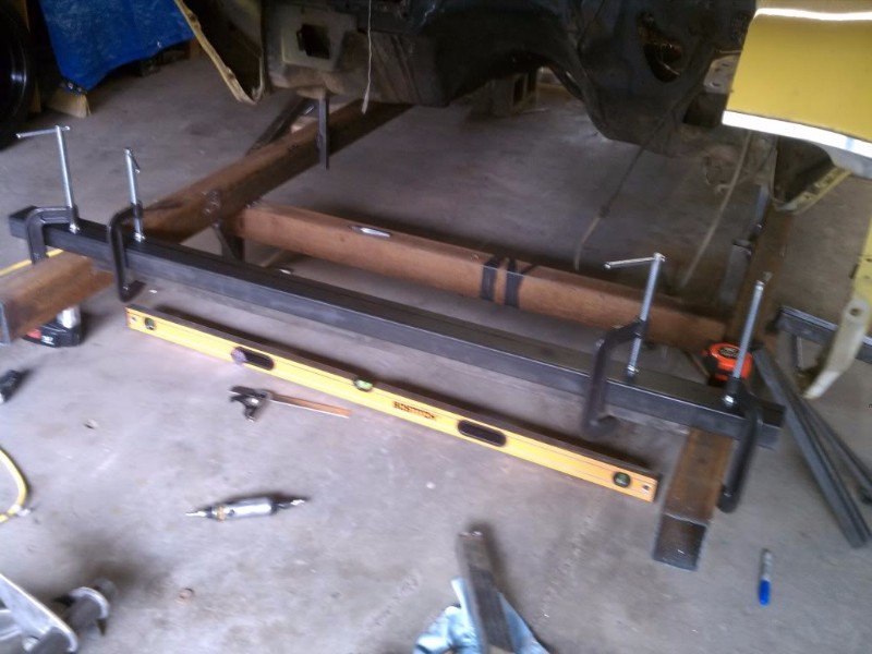
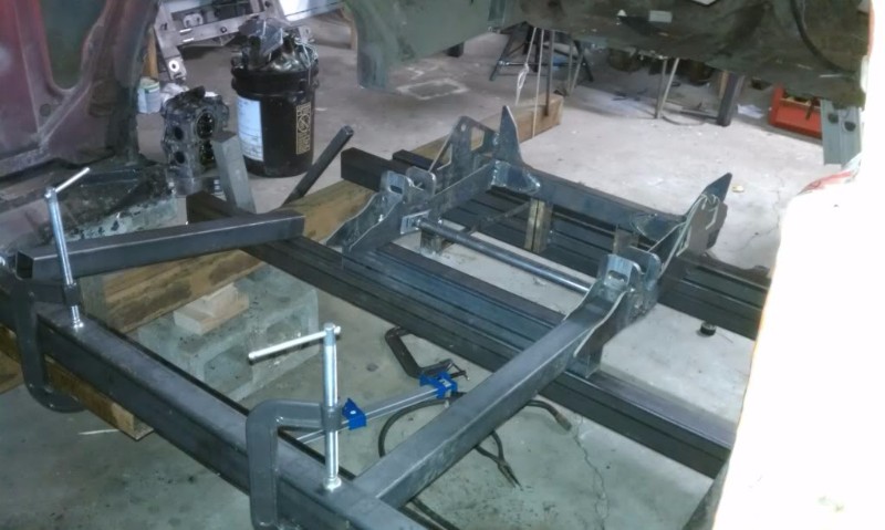
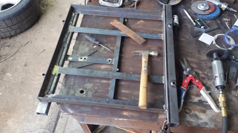
Next step: Frame jigg. This thing is square to within 1/32 of an inch, and flat to within .005" per foot. I thought having the beams right under track width of the car would be a good idea. After building it, I realized this was not the case, since I can't install a wheel and tire on the rear-end without getting them caught in the wheel well. lesson for next time is to make it a bit narrower or wider.
-
06-27-2018 #2
Registered User
- Join Date
- Mar 2011
- Location
- Portland OR
- Posts
- 26
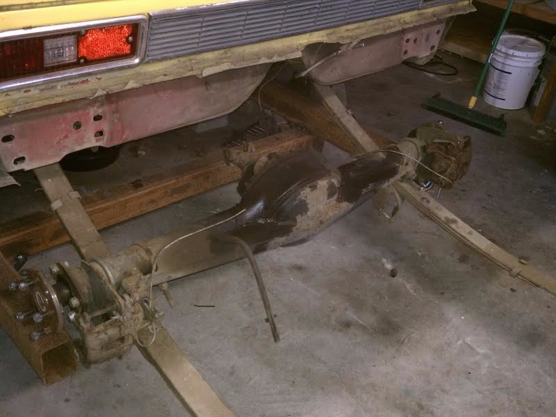
April 2011
So then work began on tearing the car down. The old 9" axle and front sub frame had to go. I was able to recoup a bit of coin by selling these, which was nice.
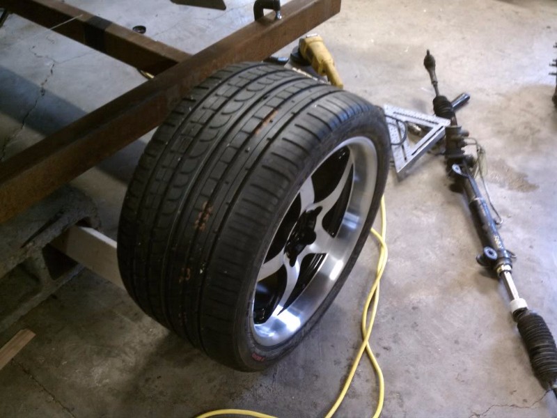
I threw one of the 295 rear tires under the front, just for kicks.
In order to design this thing, I needed the tires and wheels, so I could figure out the track width. So i spent $1200 on tires and wheels! Aint no thang. Fronts are 265 35 17s, the rears are 315 30 18's. I also bought the corvette front and rear suspension drop-outs, and transmission.
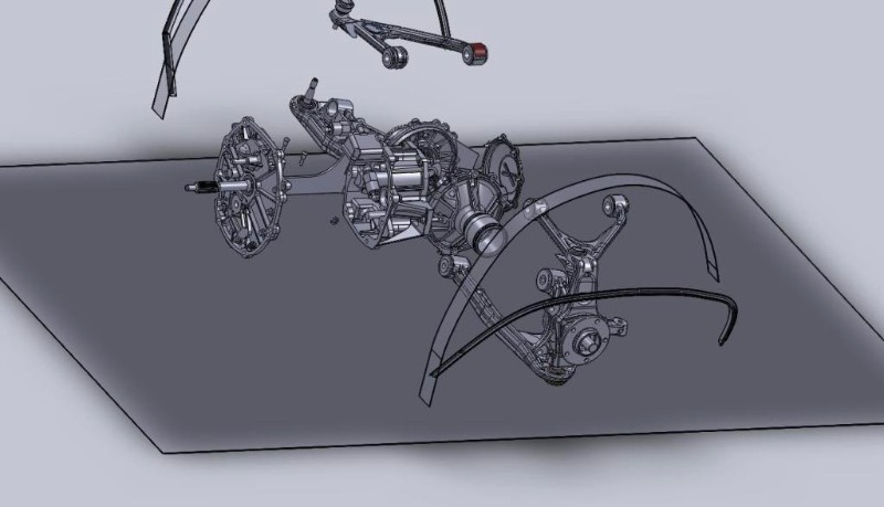
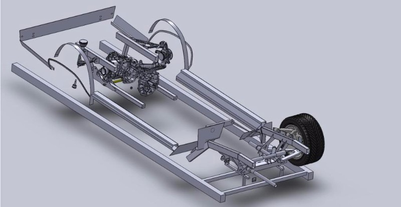
And with that, I began the design. All CAD'd so I could have pieces cut on a water jet.
I needed to narrow the track width about 3 inches... the only steering rack that was close to the right width was from a 93-02 camaro. It is 4 inches narrower than a C5, but mounts differently.
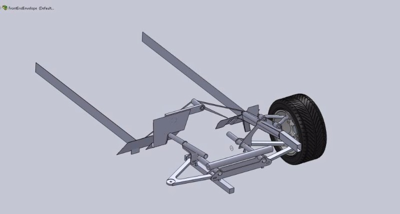
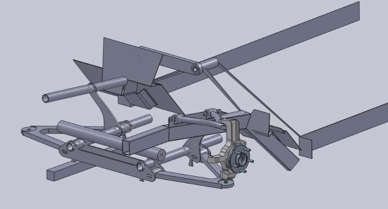
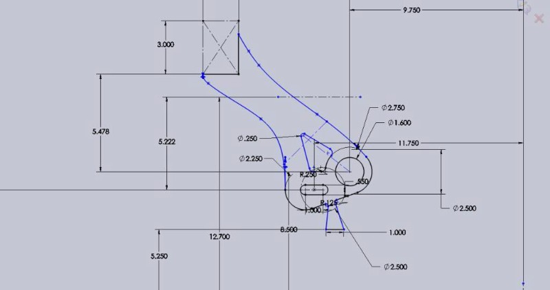
After finishing the design, I had the parts cut out on a water-jet.
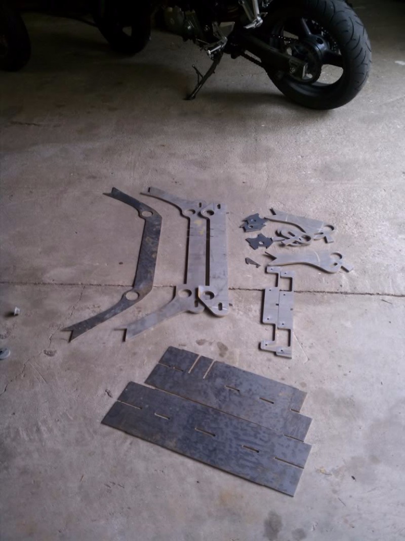
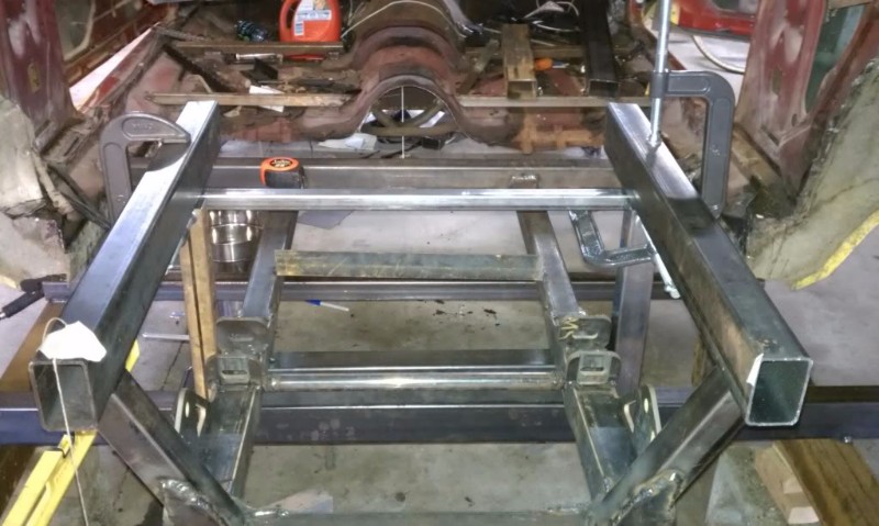
At this point, I needed to build my jig. I had all of the pieces cut out so they had a "datum" tab that was on a plane 5" above the simulated ground. i needed to build the rails for that to sit on.
-
06-27-2018 #3
Registered User
- Join Date
- Mar 2011
- Location
- Portland OR
- Posts
- 26
May/June 2011
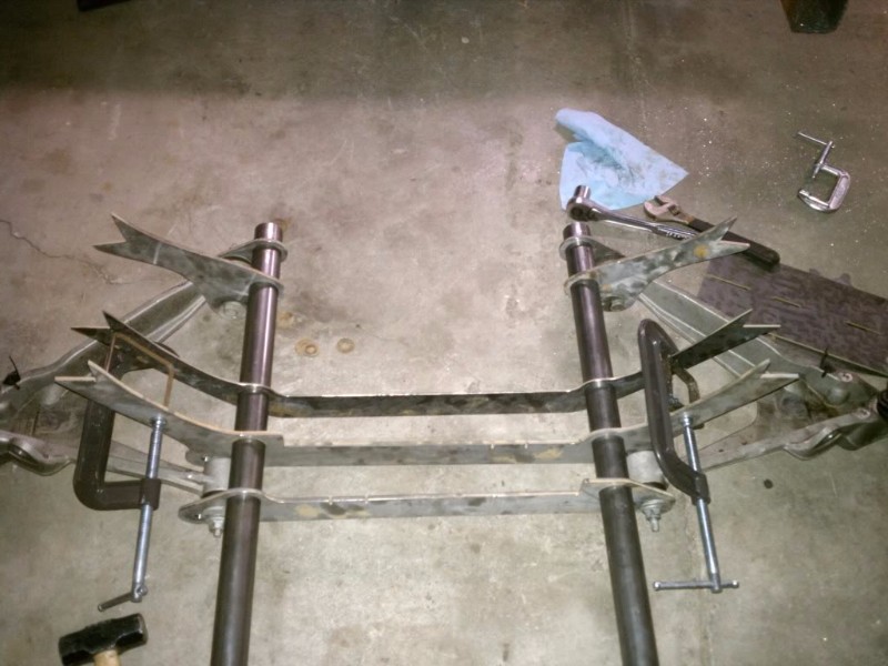
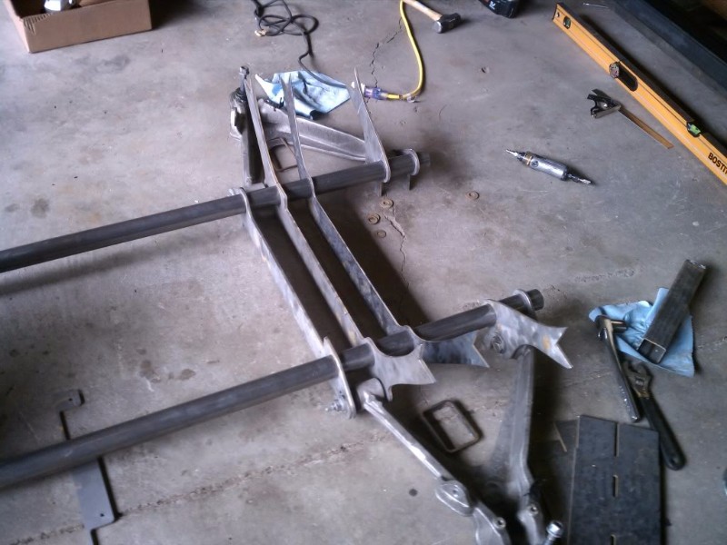
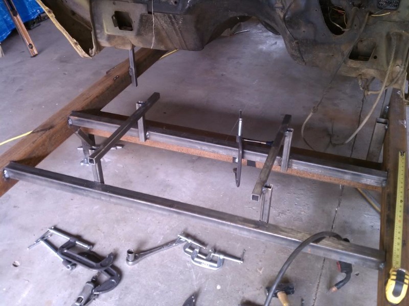
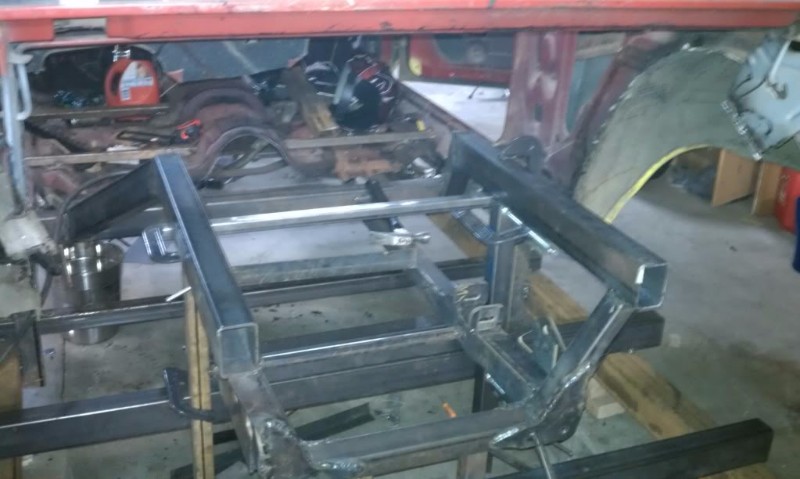
And, the assembly begins.
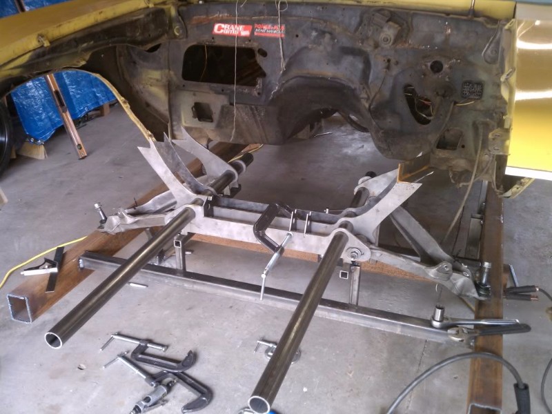
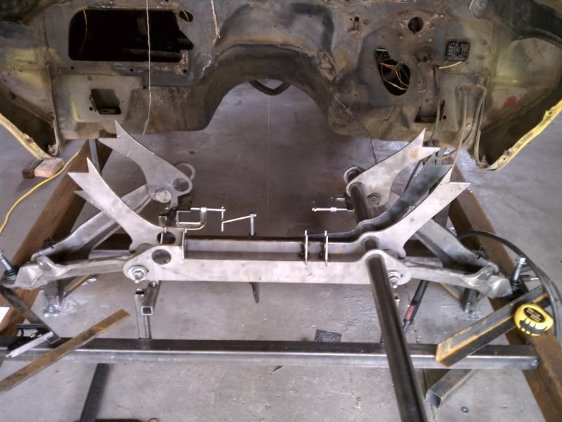
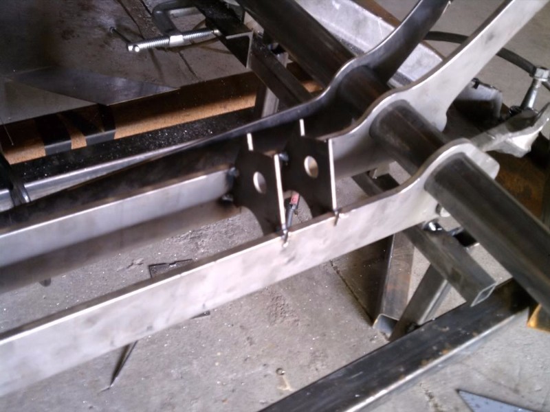
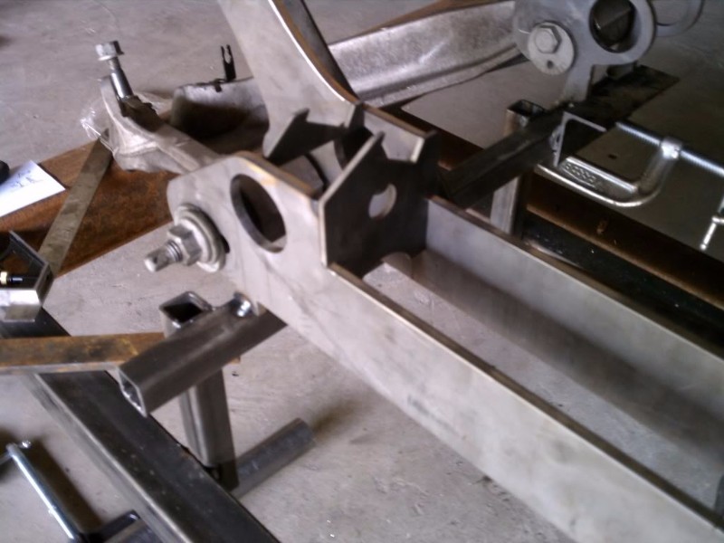
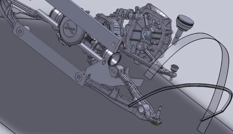
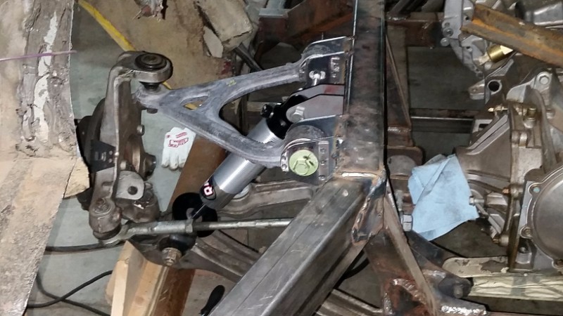
I spent about two hours tweaking and finessing the front cradle to be square. Doing this, you find out that factory control arms aren't perfect. Turns out the left control arm is sprung about .090 too far. I ended up getting the whole thing squared to itself within .032, and to the chassis to .032 as well.
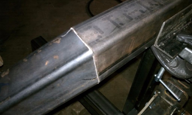
One of the cool things about using precision water-jet cutting to make these parts is that I was able to make most of the parts self-fixturing. See the steering rack mounts below.
At this point, I started doing track-days on my SV650... this pretty much ate all of my car budget and time, so I didnt start working on it again until a few weeks ago.
By the way, does anyone from this site do car track days at Oregon Raceway? that track is amazing. very technical.
I'll post some more pics in a few.
- - - Updated - - -
Fall 2011
Now that the front suspension was installed, it was time to begin designing the rear suspension. I decided to start by laying-out the stock control arms, lacking good CAD models.
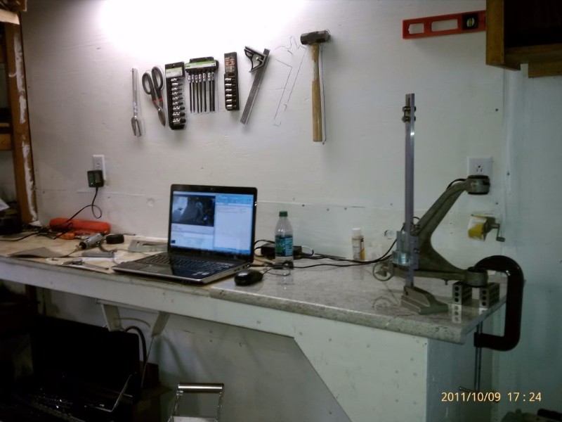
I bought a slab of granite from a counter top store. Scratch that, I bought three. I blued it up and calibrated it to a certified granit block, found it to be within .005 of flat... the other two were flat at about .020... Just an FYI for those looking fo an inexpensive super-flat surface.
I also digitized the wheel-wells of my car to check wheel fitment.
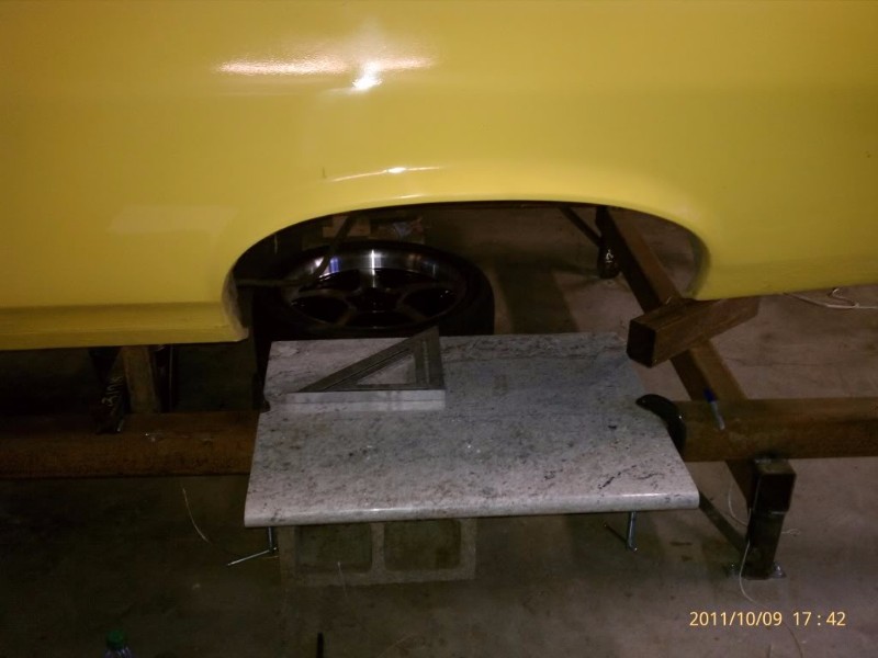
For a little bit of motivation, I threw a rear-wheel in there after i cut the wheel-wells out.
I decided I needed more accurate data about the geometry of the transmission, so I called up a locale guy who is quite well-known in the pro-touring community to use a CMM arm to measure the parts... we worked something out and I got some very good cad models. So then CAD design commenced:
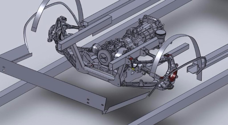
- - - Updated - - -
Fall 2011
I left off on updating this thread about the time I finished designing my rear suspension... some screens shots of the cad files can be seen in my earlier posts.
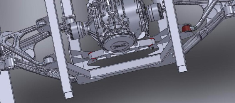
After design, I went on to waterjet/laser the parts out, and began fabrication:
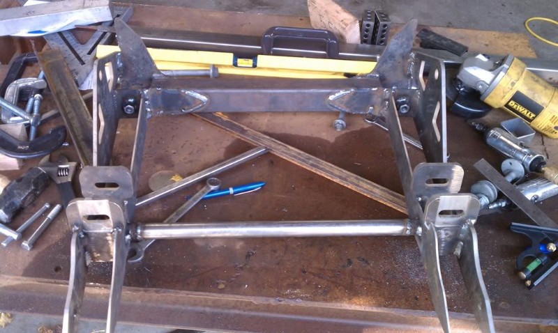
Gotta love a nice CNC transmission support cross member:
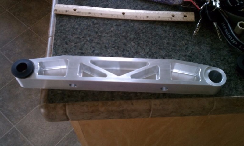
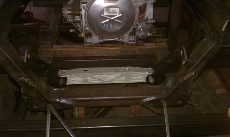
Next up: How to connect the engine and transmission...
- - - Updated - - -
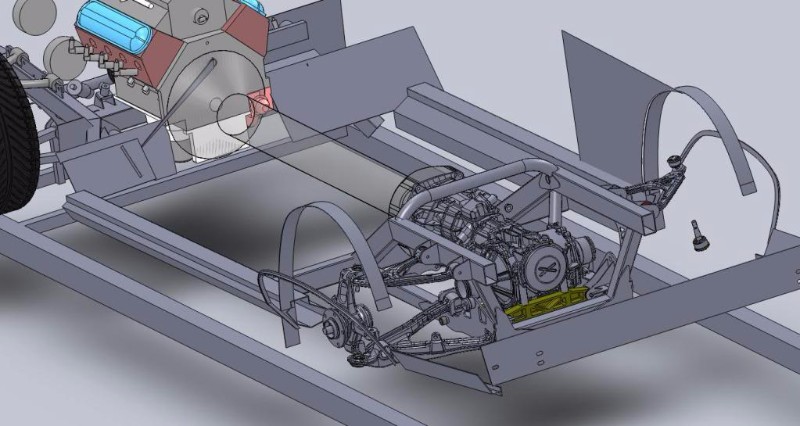
Winter 2012 Through Fall 2014
Now I needed to figure out how to connect the engine to the transmission. The OEM solution is the 'torque tube.' there are front engine mounts, a long tube that connects from the bellhousing to the transmission, and transmission rear mounts. initially, I decided not to use this since it is large, and I was worried about interior room. Also, it is too short, and getting a longer shaft that will not vibrate is tough. So, an open shaft seemed the way to go.
Unfortunately, Nobody makes an adapter that goes straight from the clutch to a driveshaft, so I had to design my own. I make castings for a living, so I figured I'd make up a pattern and have it made from aluminum.
Aligning the engine and transmission:
Cad model of the tailhousing casting
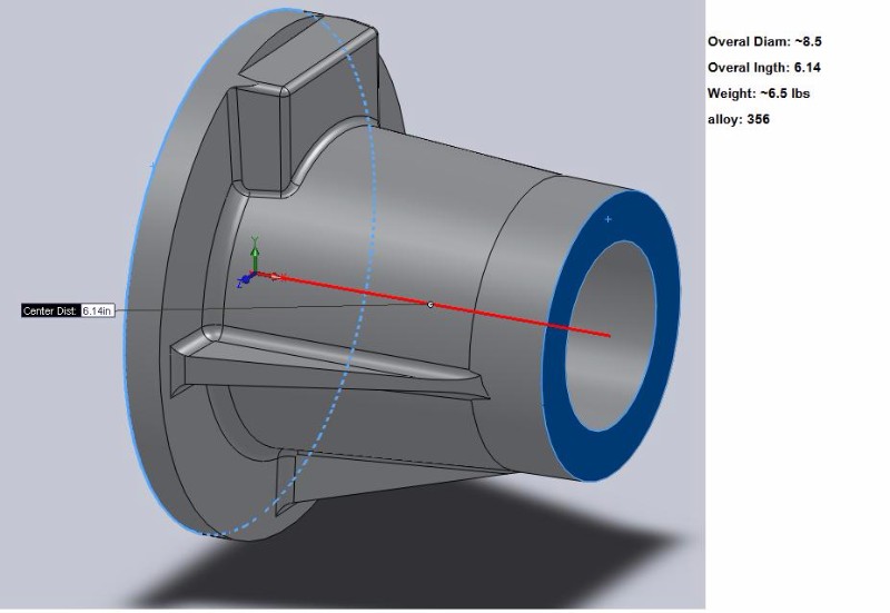
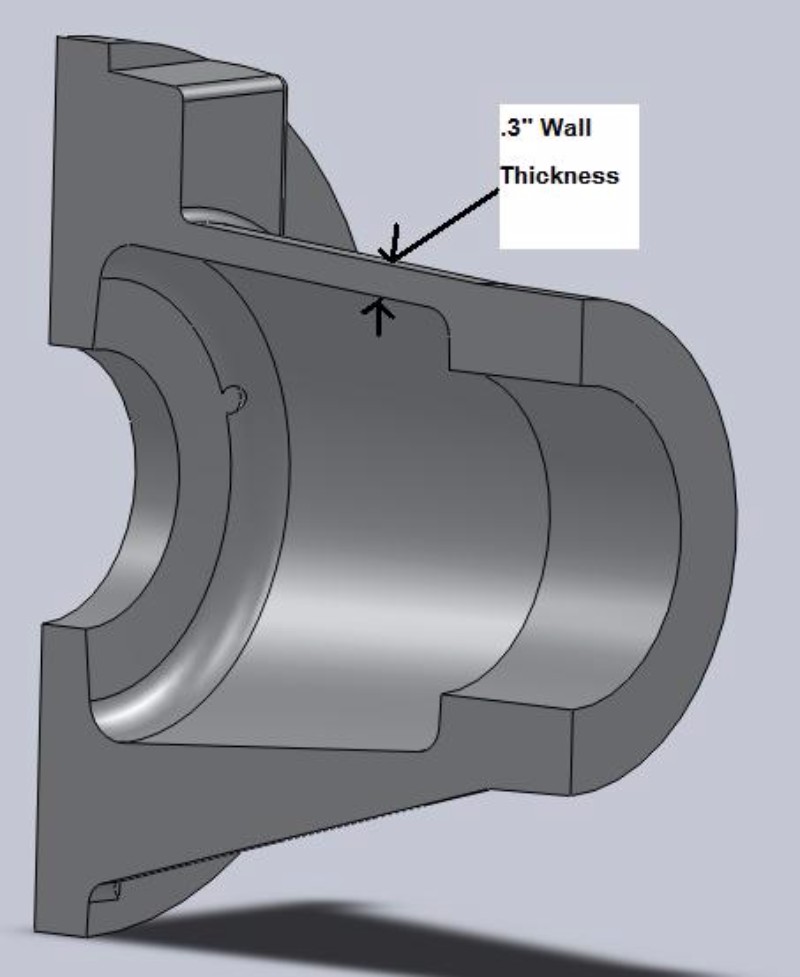
Shaft and bearing assm design
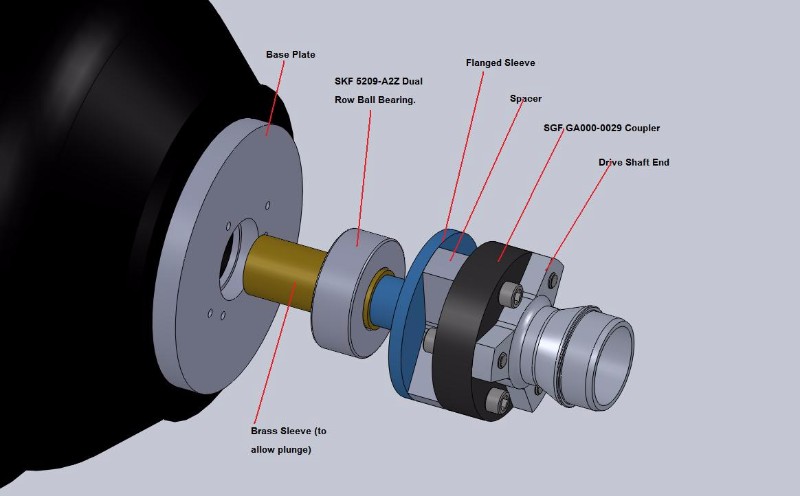
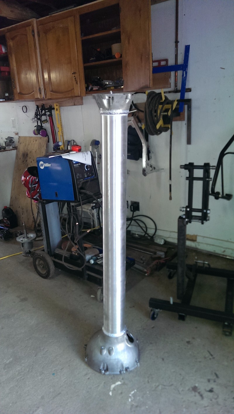
Heck I even built it!
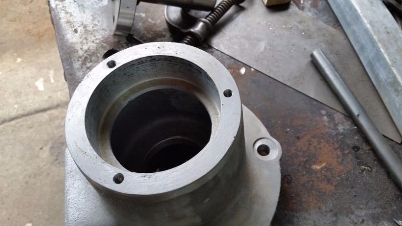
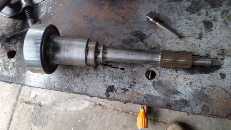
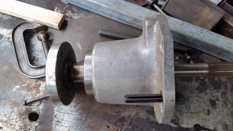
The problem is, it is too heavy. I drove a corvette, and it already seems like the syncros had a hard time with the rotating mass of the corvette shaft, let alone mine which is 4 times heavier! At any rate, I didn't like the solution, I was concerned the mounts wouldn't keep the engine in line, and I'd have a hard time lining everything up if I ever pulled the engine. So, I decided to go back to the torque tube.
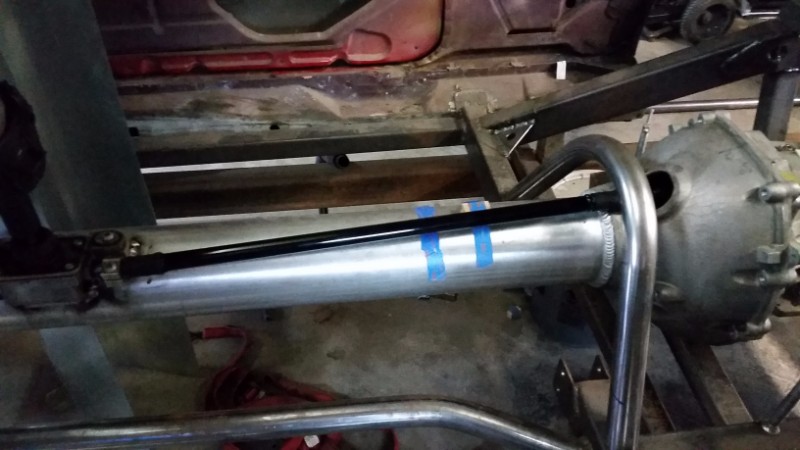
A local shop had experience lengthing these, so they did it for me. Turns out DriveShaftShop.com can make a shaft that can handle the torque and RPM just fine, so there really is no reason not to use the torque tube. It just required some diligence in making the tunnel tight to the tube, as much as possible.
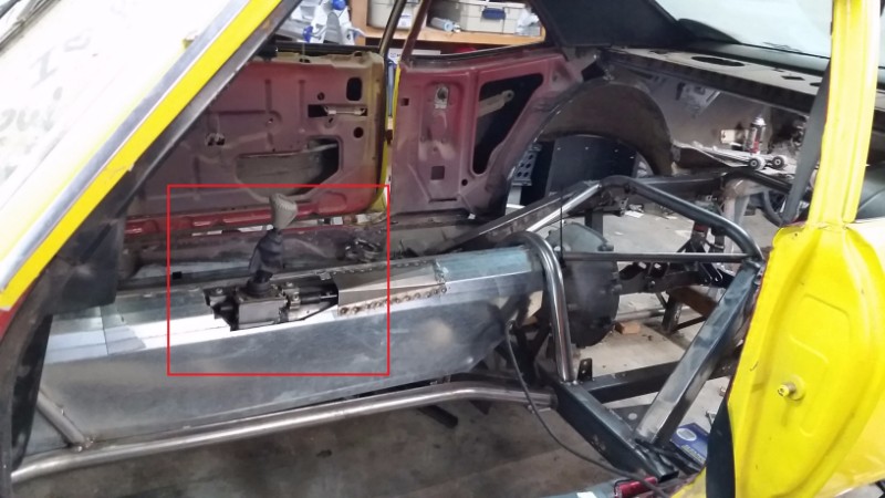
With the torque tube in hand, mounting the shifter and installing the linkage went quickly, as did installing the tunnel:
- - - Updated - - -
Fall 2015 Through Spring 2017
More progress has been made!
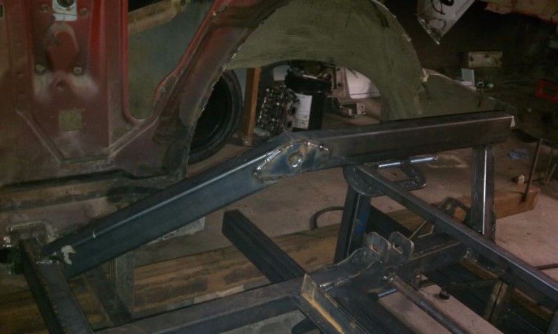
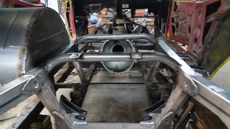
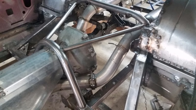
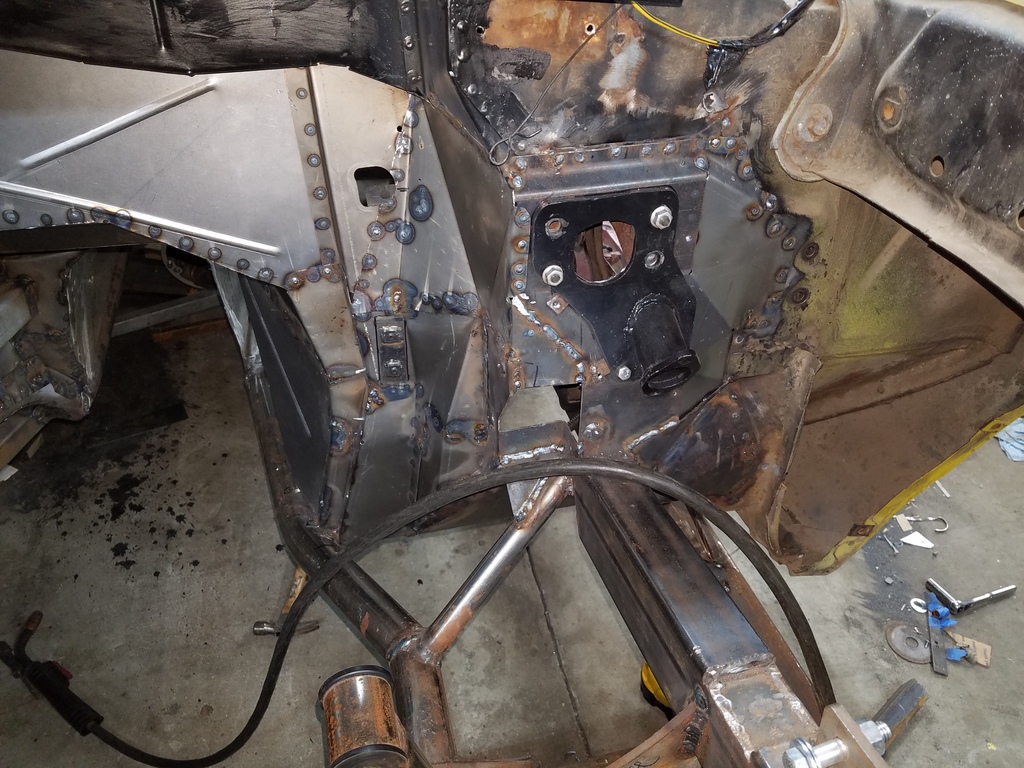
With the transmission tunnel installed, I attached the upper suspension mounts:
I wish I'd taken more photos... but that's the rear suspension mocked up. Now, wheel wells begin:
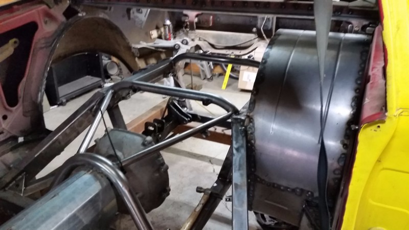
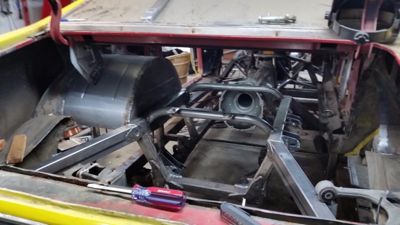
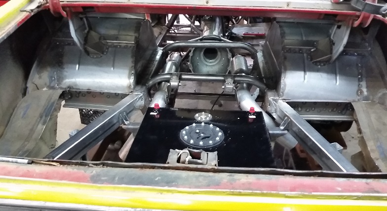
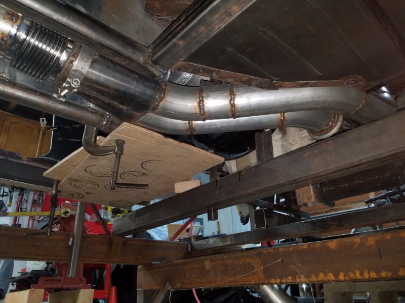
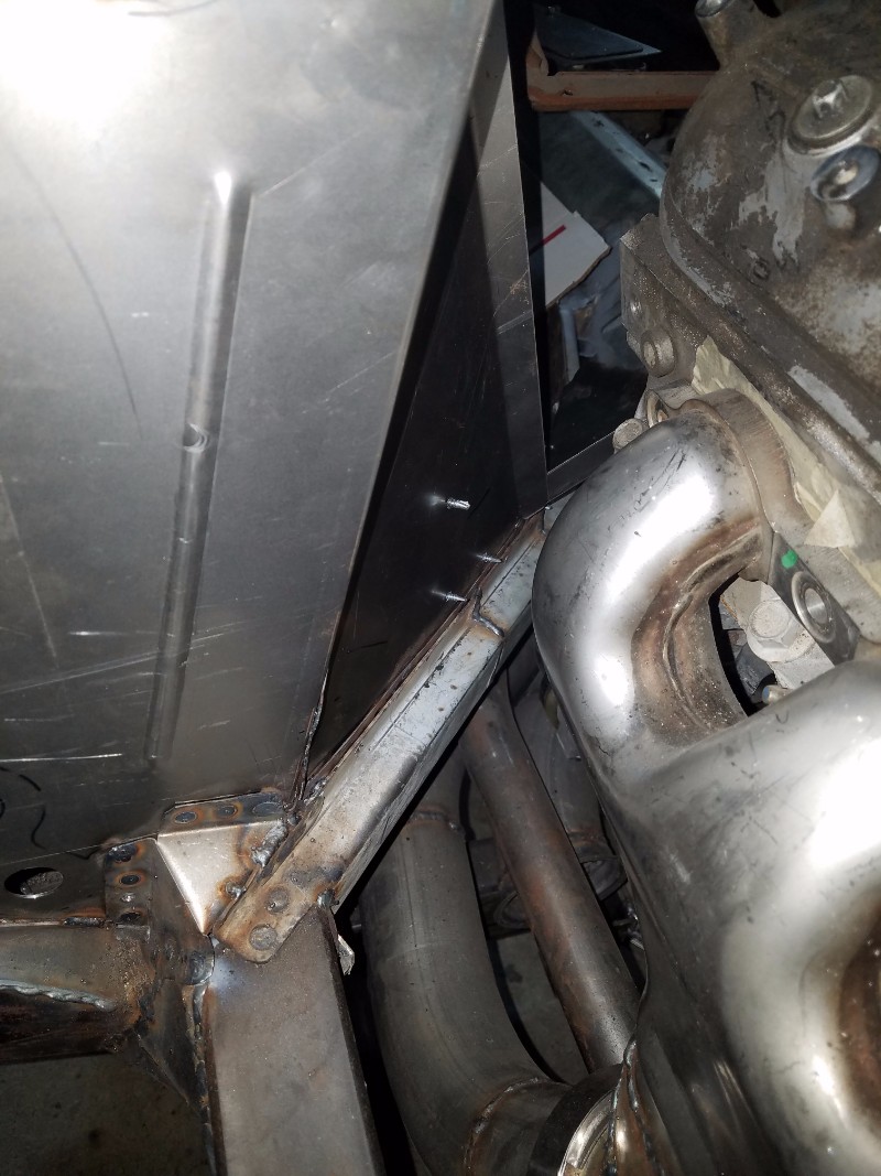
I did the exhaust before I removed the transmission for working on the wheel wells, but this is a pic of it installed. It fits snug, but I can remove it all fairly easily.
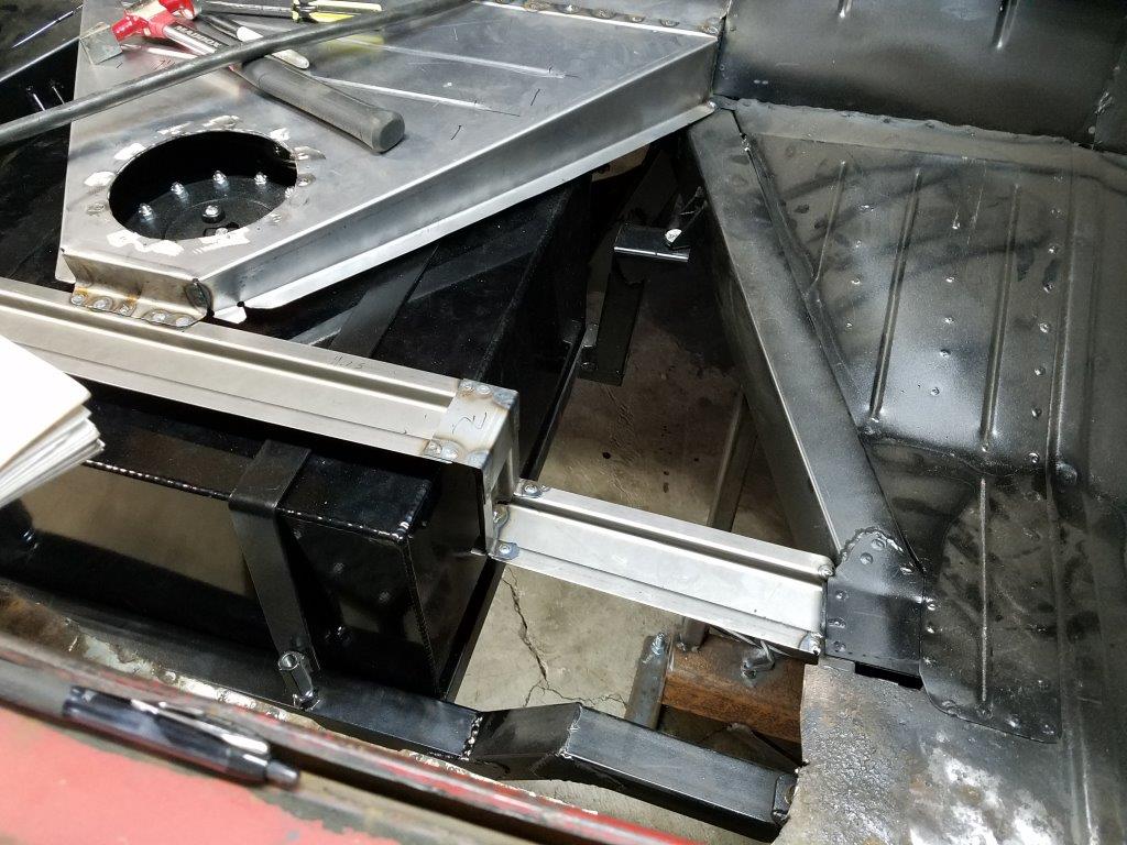
Fuel cell Mount
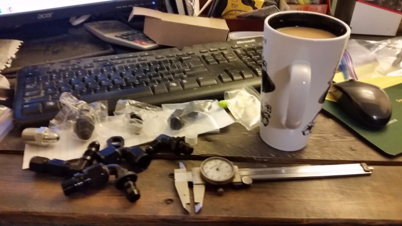
I bought a summit fuel cell, 15 gallon with the little sump, and a gauge. To make the transmission removable, I need to be able to drop the cell out easily. Here's what I came up with, after a little Coffee and CAD:
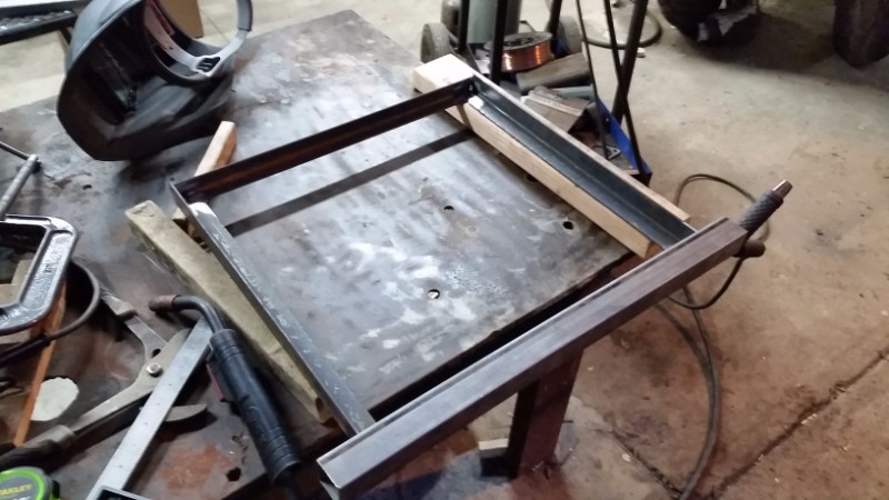
Next, I'm going to finish mounting the fuel cell, then I'll build the straps to retain it.
- - - Updated - - -
Summer 2017
Here Goes again!
Between now and the last time I posted, I did manage to finish the fuel cell mounts, and even primered the back-half of the car's frame, wheel-wells, and suspension mounts. I did not, however get pictures... and I proceeded to stack parts and materials into the trunk of the car, meaning I won't be getting better pics for a while.
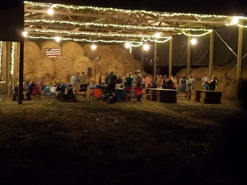
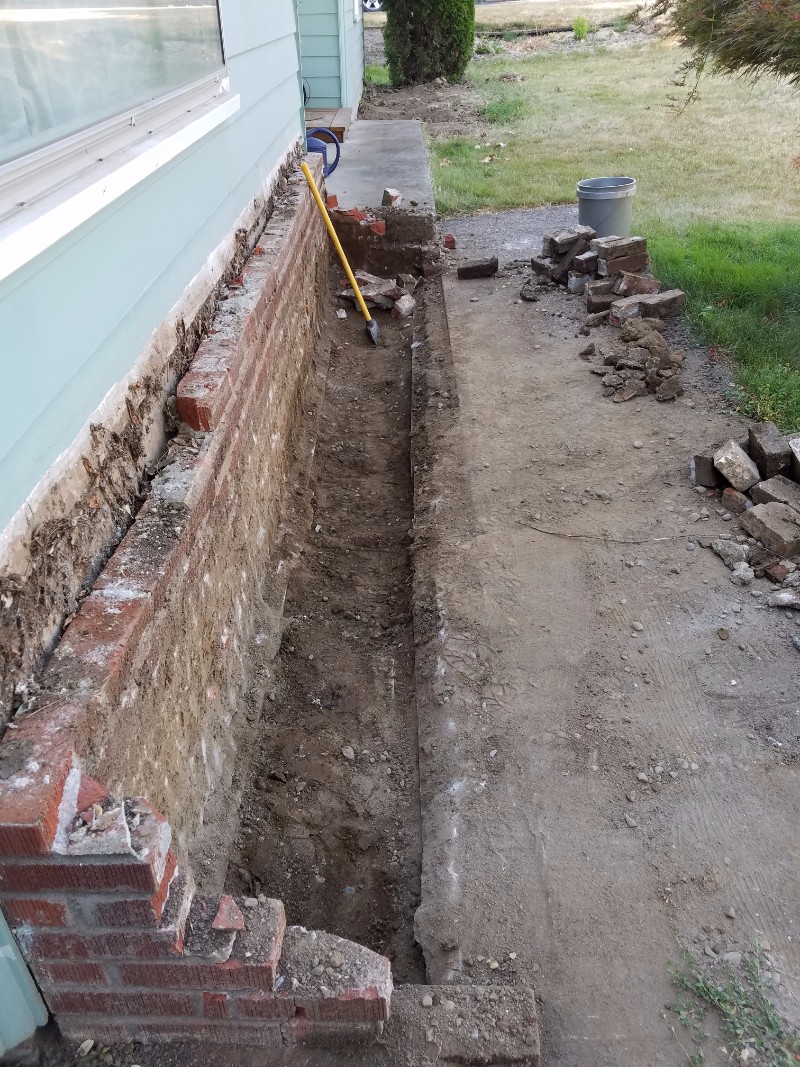
After primer, I got a bit distracted from the car for the summer. Barn parties, house projects, and even some track time in my Chumpcar racer stopped progress from July 15th until about 3 weeks ago.
Anyway, I've been busy though!
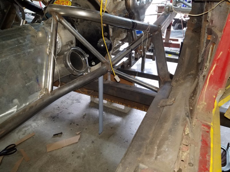
I decided to transition to the front of the car. There's alot of reasons for this, but mainly it comes down to poor design of my chassis jig... I can't get under the car if the floorboards are in!
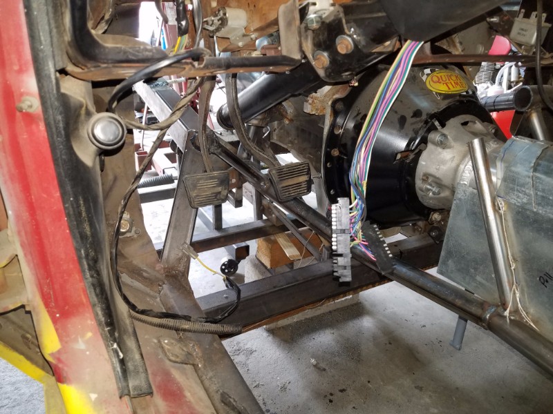
The first step was working on the driver's position, pedals, and steering column.
I bought a column from a '96 camaro. I transferred the Nova columb brackets to it, and shortened it. There's enough info on how to do that out there, that I won't go into it. It's not to hard though.
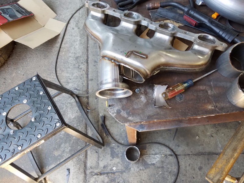
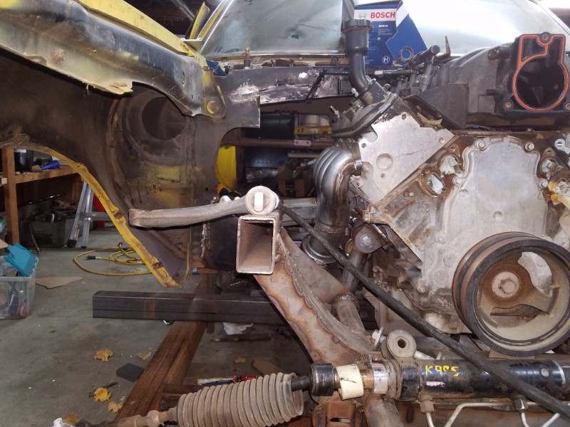
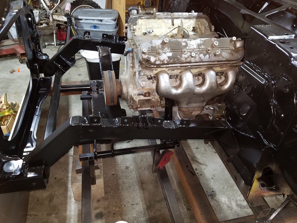
I realized I was going to have to decide on an exhaust system. After some research, I decided it was either custom headers, or modify some LS7 manifolds.
LS7 manifolds are nice, the have a dual layer, and make really good power.
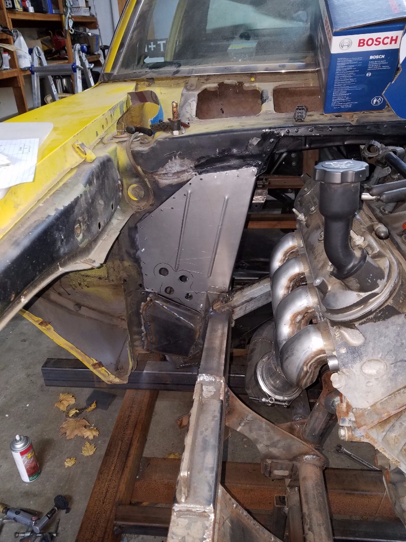
I purchased a pair, and cut the flanges off. You can see below, I have alot of room for the steering linkage.
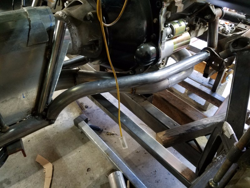
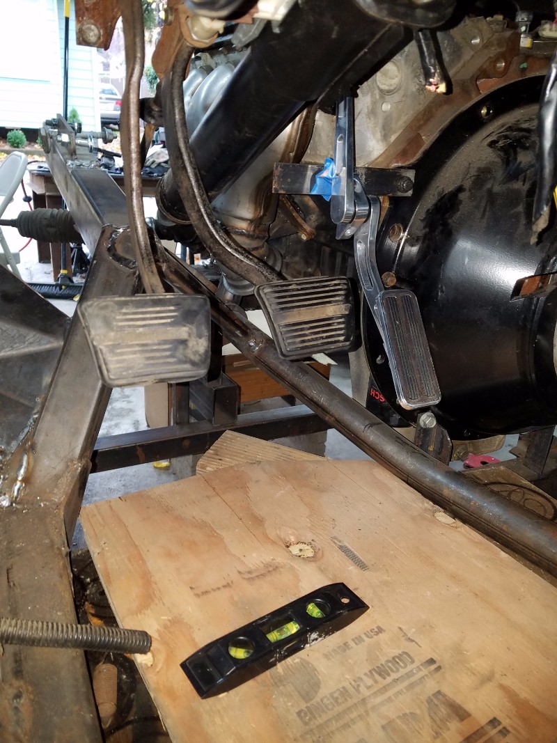
The picture below shows the clutch and brake pedals installed. While trying to fit the column and pedals, I found that some of the frame tubes I'd installed back in 2012 would not work, as they took too much of my footwell. I also found out that there was no way to get an exhaust pipe through on the driver side.
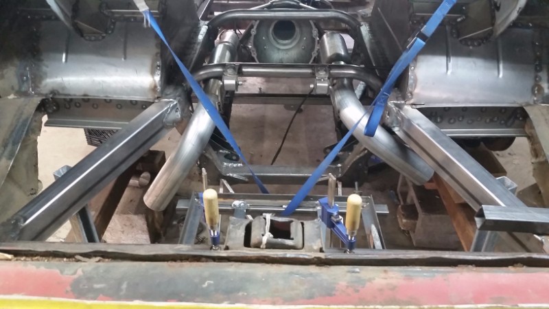
Now that I'd determined the stock pedal assembly would work, and that I'd have to hack up the frame a little bit, I dove into the exhaust. You can see below what I THOUGHT I'd do for exhaust.
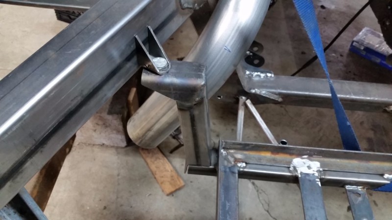
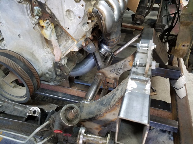
To prevent any extra encroachment into the passenger footwell, and to allow room for an AC evaporator, it worked best to route two 3" pipes next to eachother, and to join then under the torque tube. I set out to modify the manifolds, and re-did the frame tubes in the area to make room.
- - - Updated - - -
Winter 2017
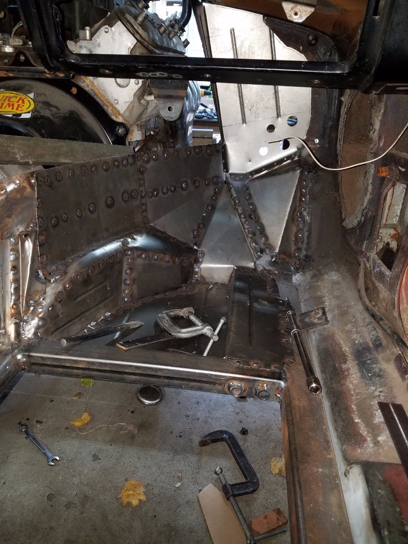
Once the exhaust was done, I purchased my Vintage Air kit, test fit it, and built the passenger size footwells.
I figured i'd better check and make sure my AC kit would fit. I wanted a low mount one. It fits, quite snugly!
So, back to the pedals.
I needed to make a bracket to test the location of the gaspedal. It wasn't working to test the pedal placement without the pedals returning, so I rigged up some springs.
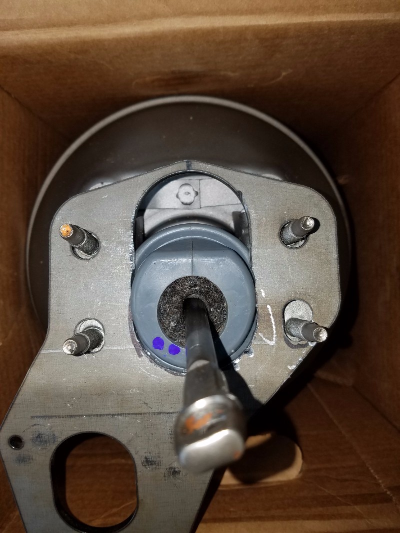
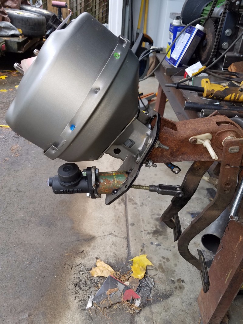
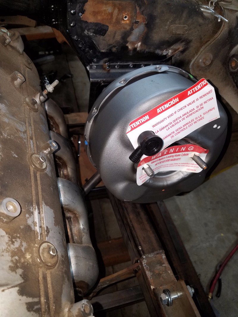
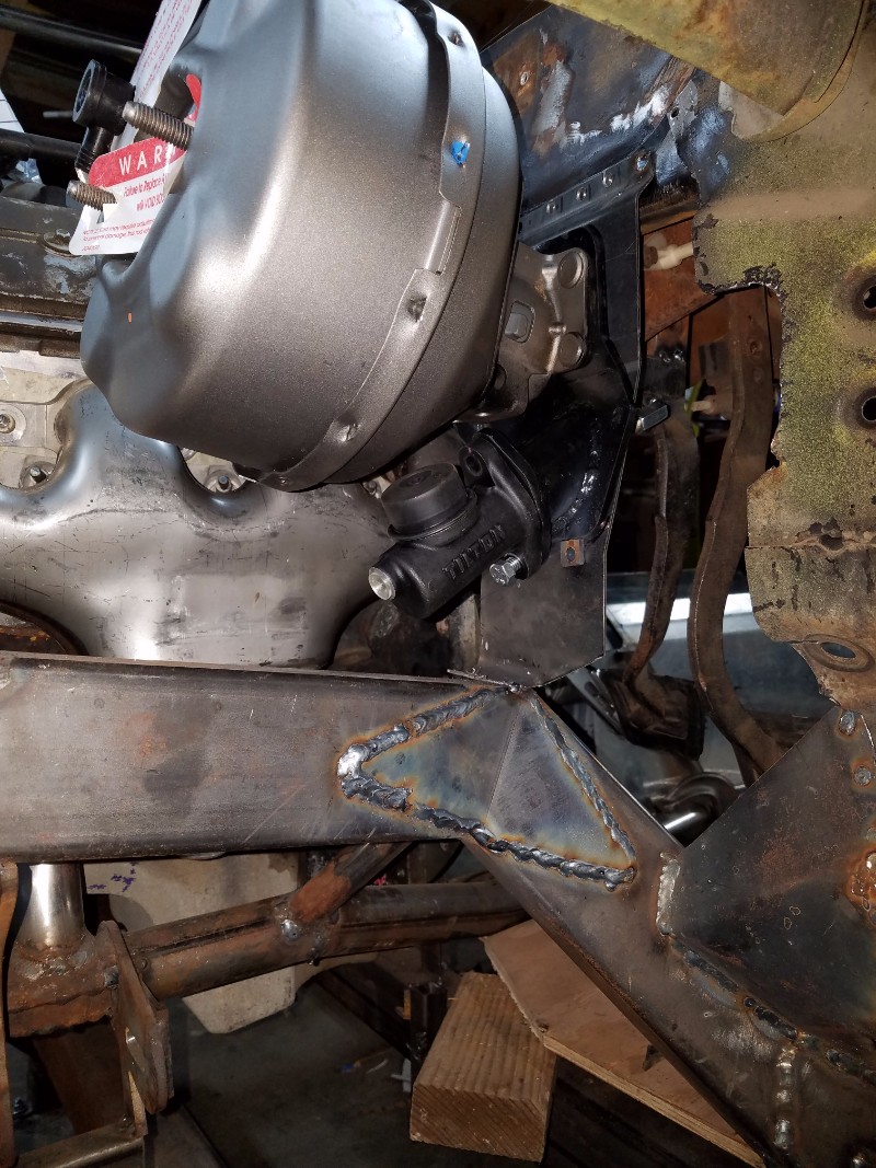
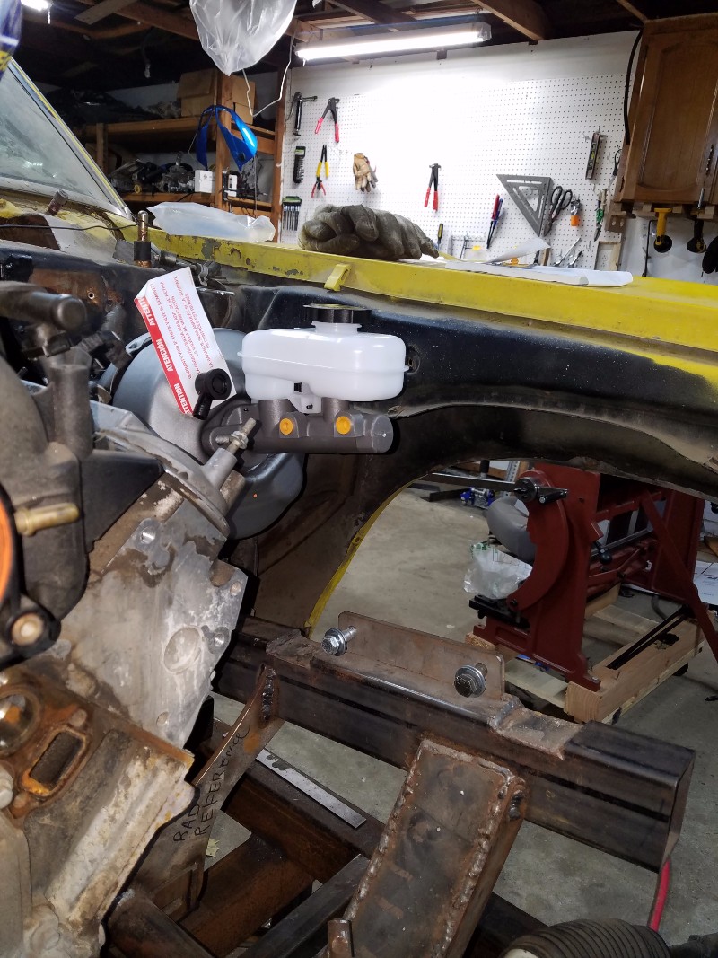
Now, I'm not a guy who invents the wheel when he doesn't have to. So I borrowed heavily from RomanCommander's build, and used the same bracket, booster, and clutch master he did.
- - - Updated - - -
Winter 2017
More progress made!
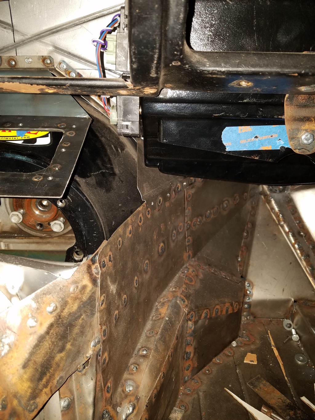
This shows my AC unit installed under the dash, as well as the access plate for the top of the torque tube. That will be how I bleed the clutch.
Firewall Completed! This took alot of fidding, and thinking everything through. I had to buy and install the throttle cables to make that work, install the pedal assembly, and so on. I wish I didn't have to make such a patchwork, but to get everything to fit, and given my tooling limitations, I did the best I could.
3 Coats of Southern Polyurethane Epoxy!
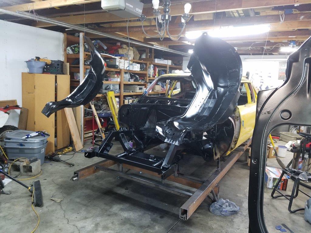
The next phase of this project is to finish the core support, inner fenders, steering linkage, and swaybars.

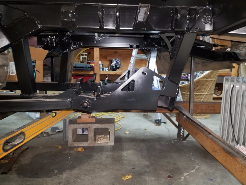
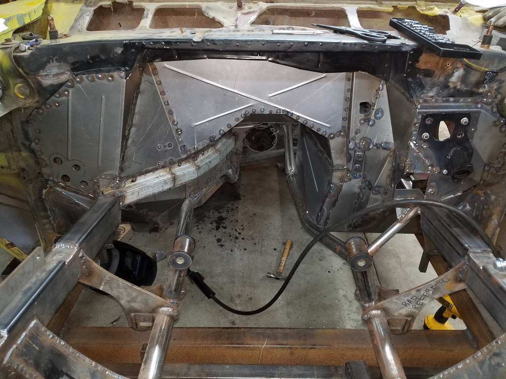
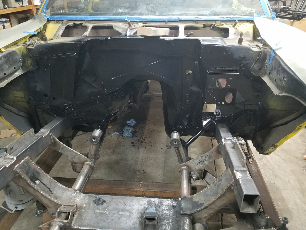
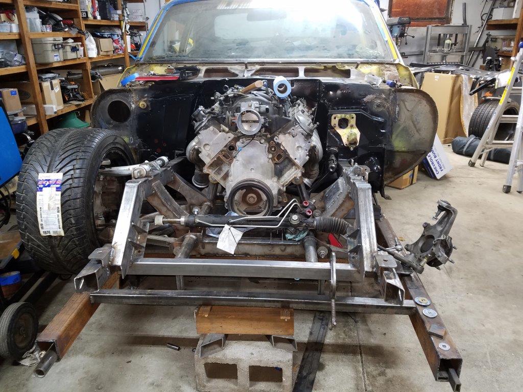
Core support installed.

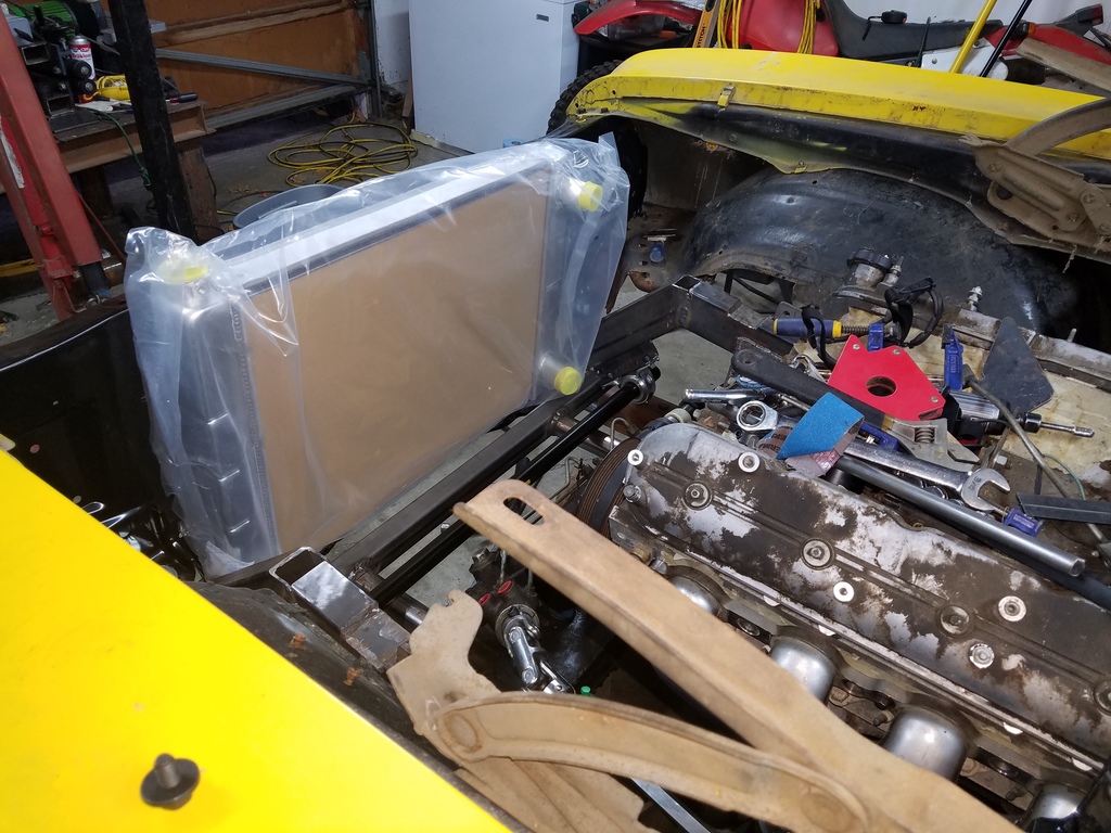
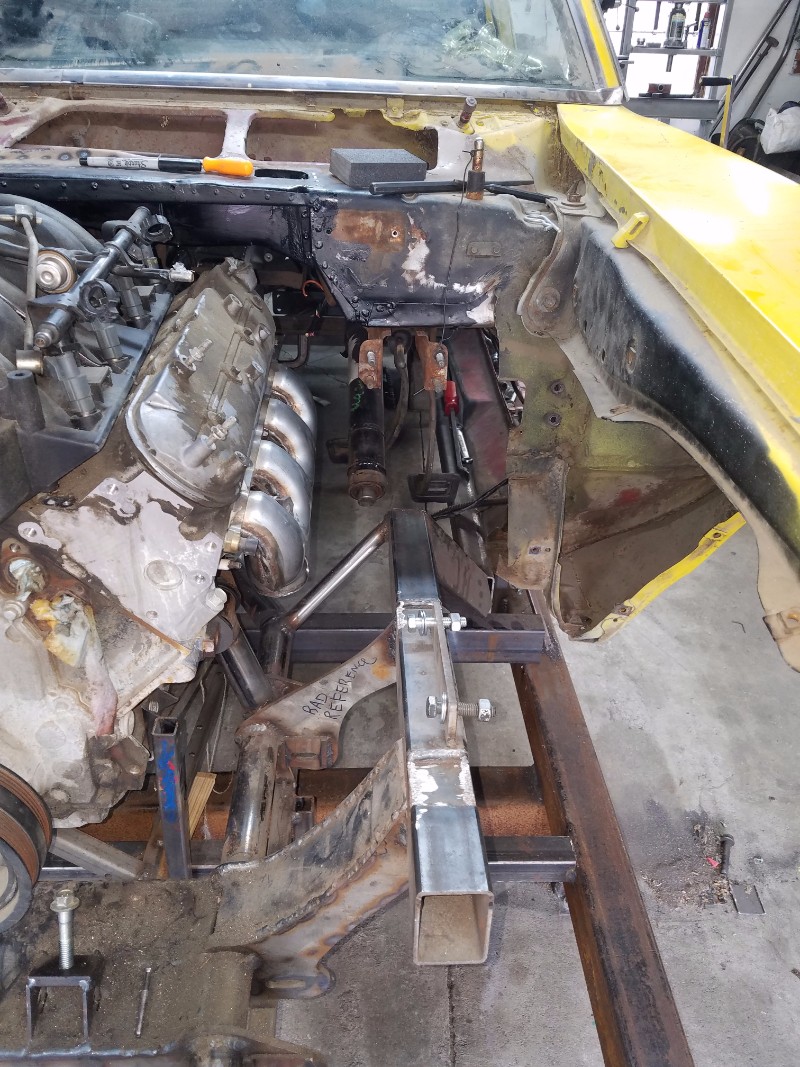
Motor placed, radiator just set in for reference. Lots of room for a fan! You can see the downbars, and swaybar tube mounted. the C5 bar is too wide, given that I narrowed the suspension up by 4 inches. I bought a speedway Engineering hollow tube, and pillow blocks.
- - - Updated - - -
Jan/Feb 2018
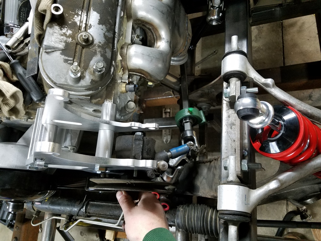
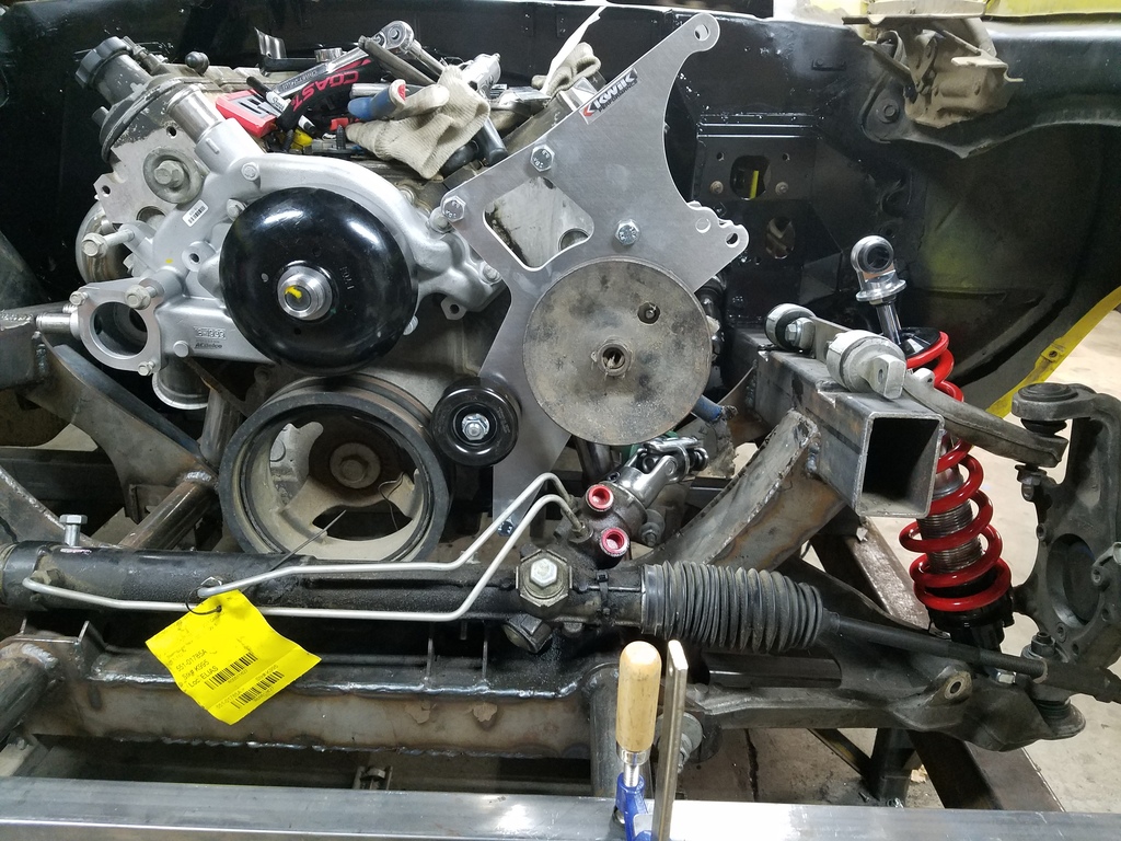
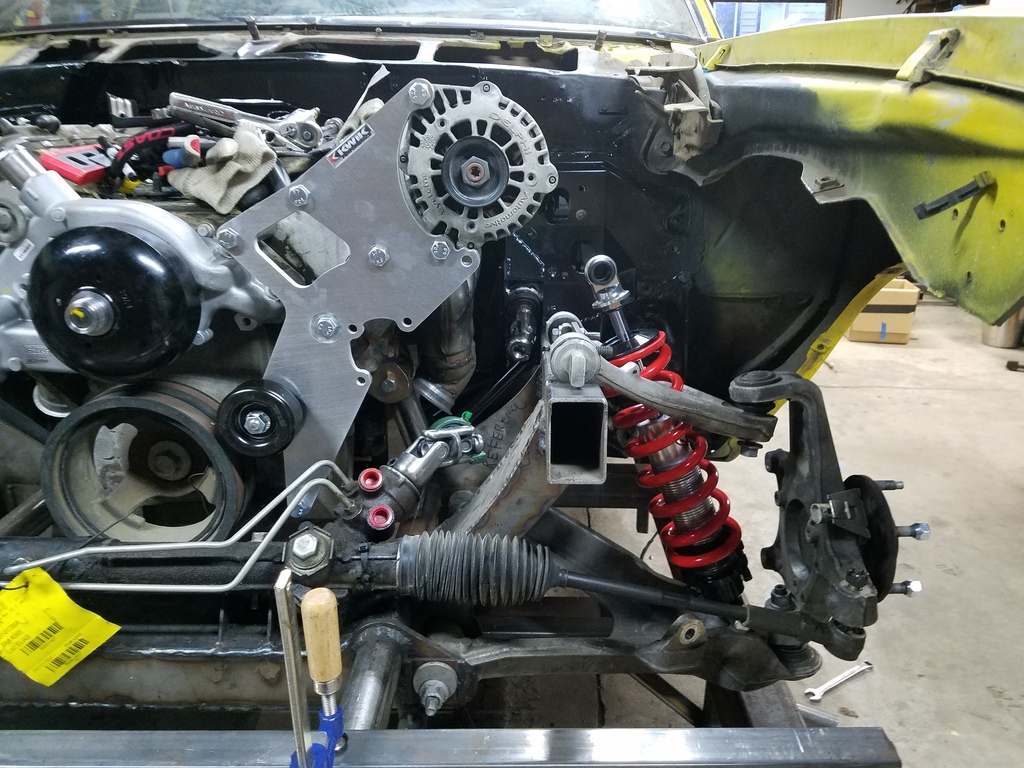
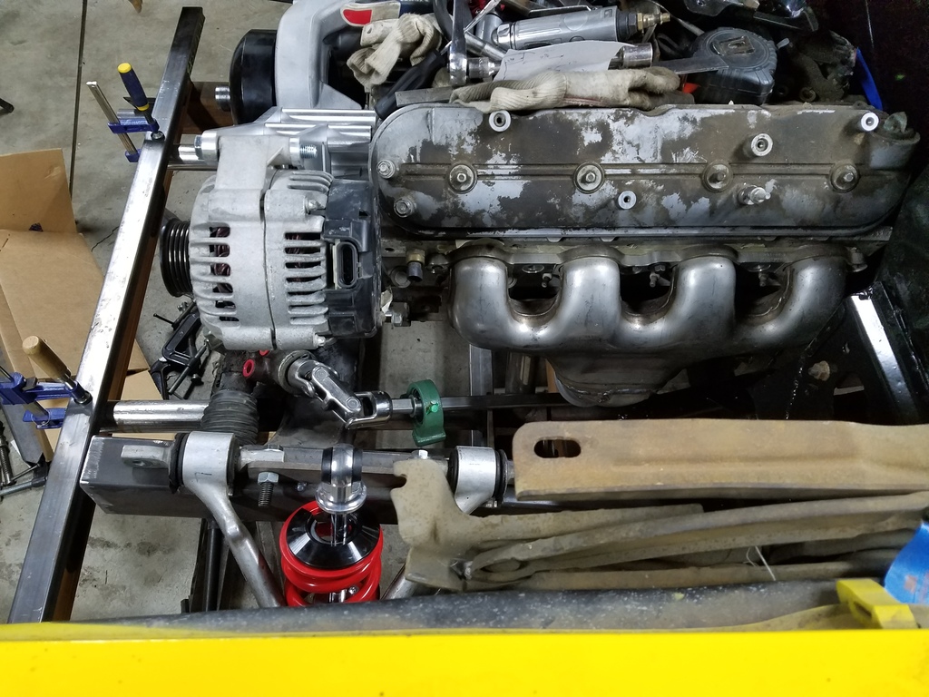
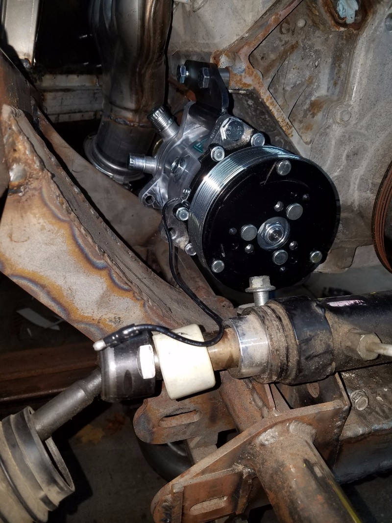
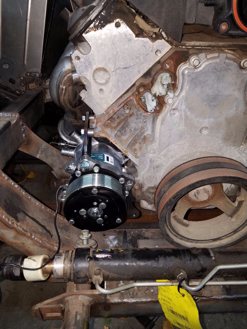
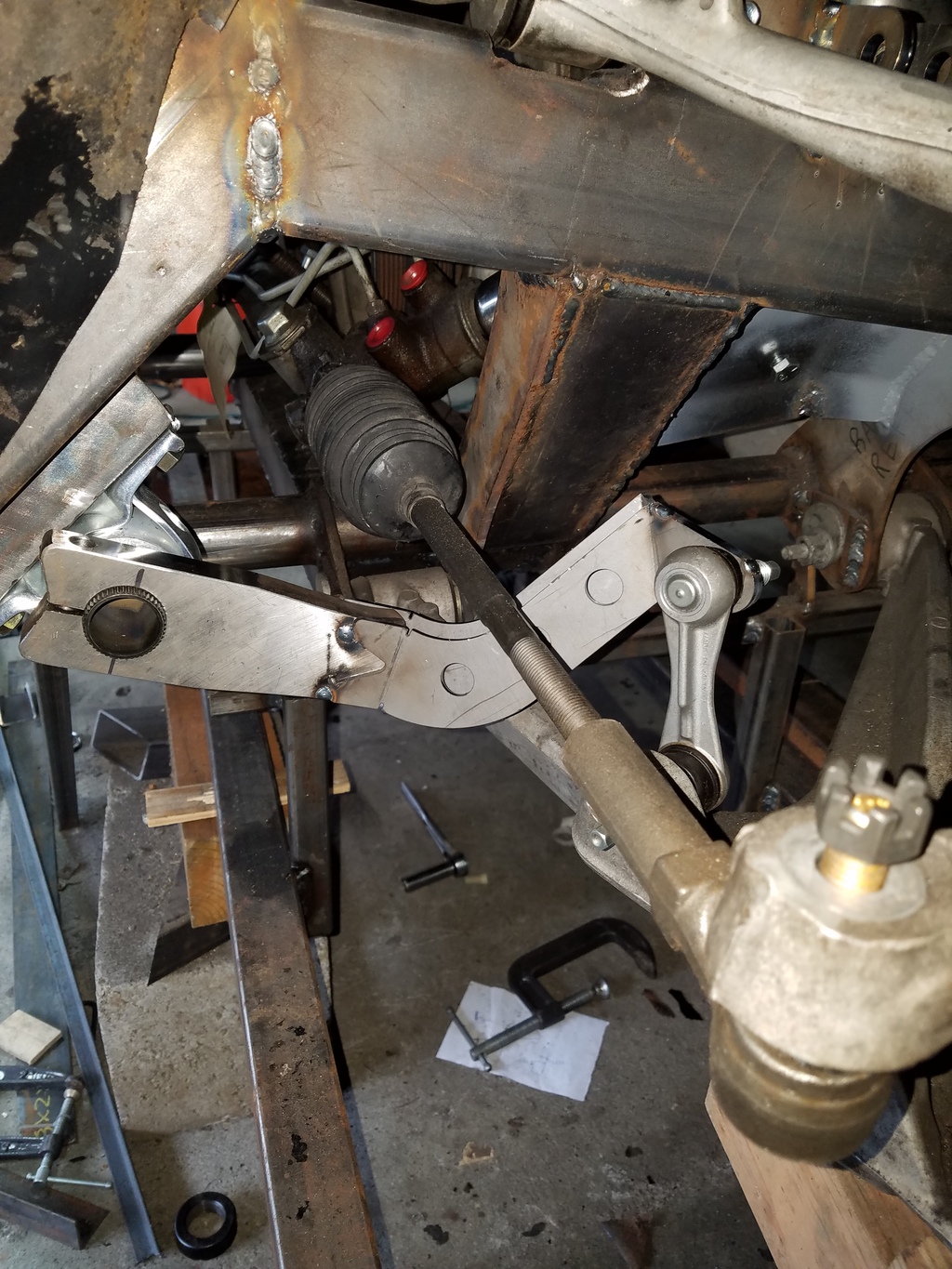
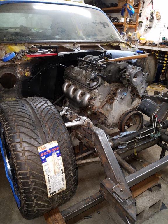
At this point, it was time to finish the steering shaft. I purchased a KWIK bracket set to mount my alt and PS pump. Perfect clearance!
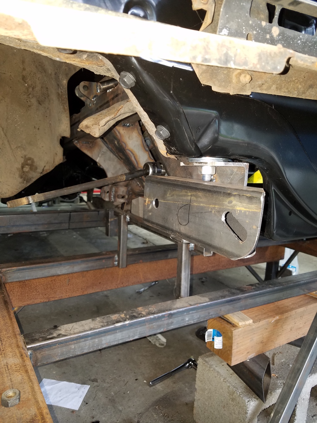
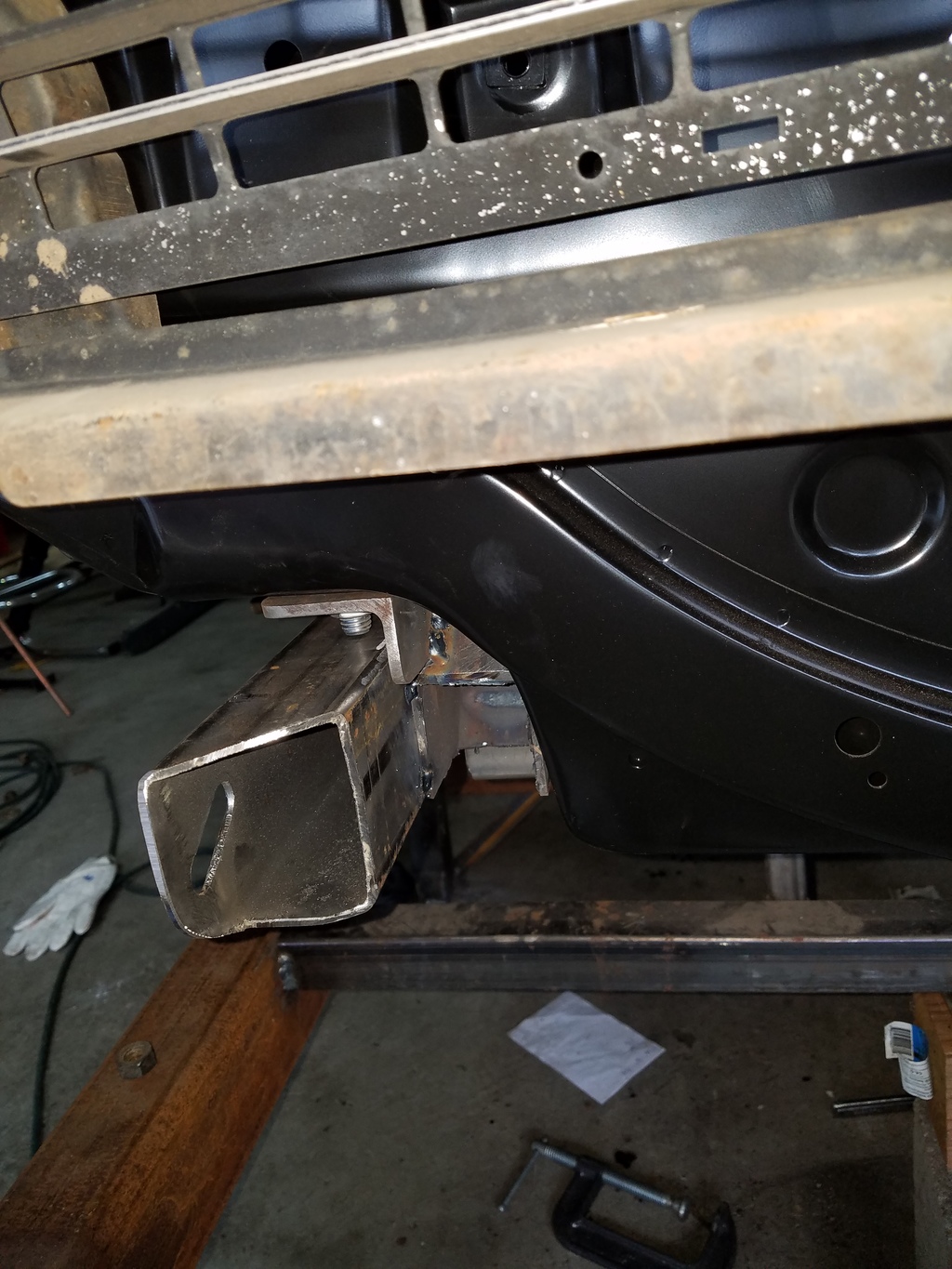
Bumper mounts...
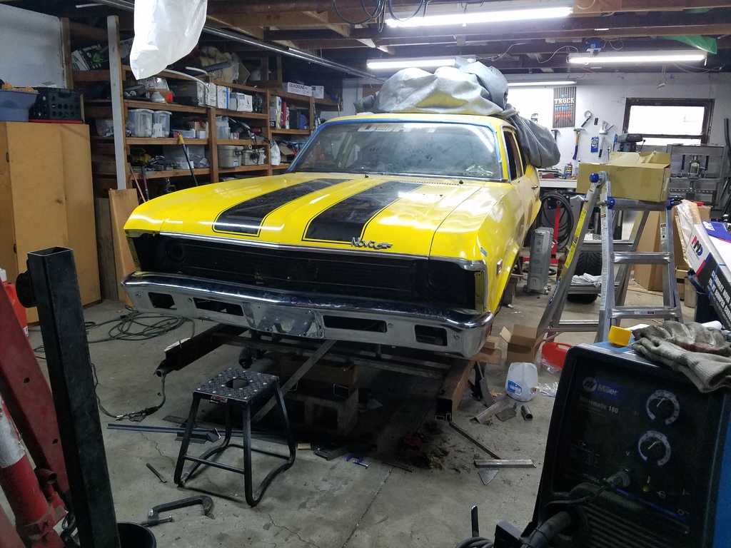
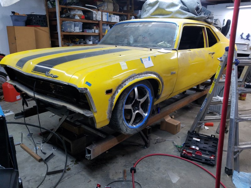
Bumper mounted. It's only roughly aligned. There is plenty of room to make it right, but I don't want to spend much time on it now. The car is looking much more nova-like than it has in a while!
Now that I satisified my need to see tangible progress, I went back to the swaybar arms. I hacked up the arms that came with the swaybar kit. I had someone lasercut some metal that I could fab the arms out of. They worked like a charm! they are all welded up, but I need to spend some time grinding welds to make them look nice before I share a pic!
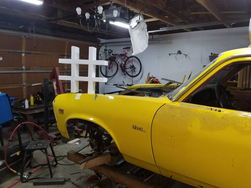
#novaProject. (The styrofoam # came with my radiator. I just had to.)
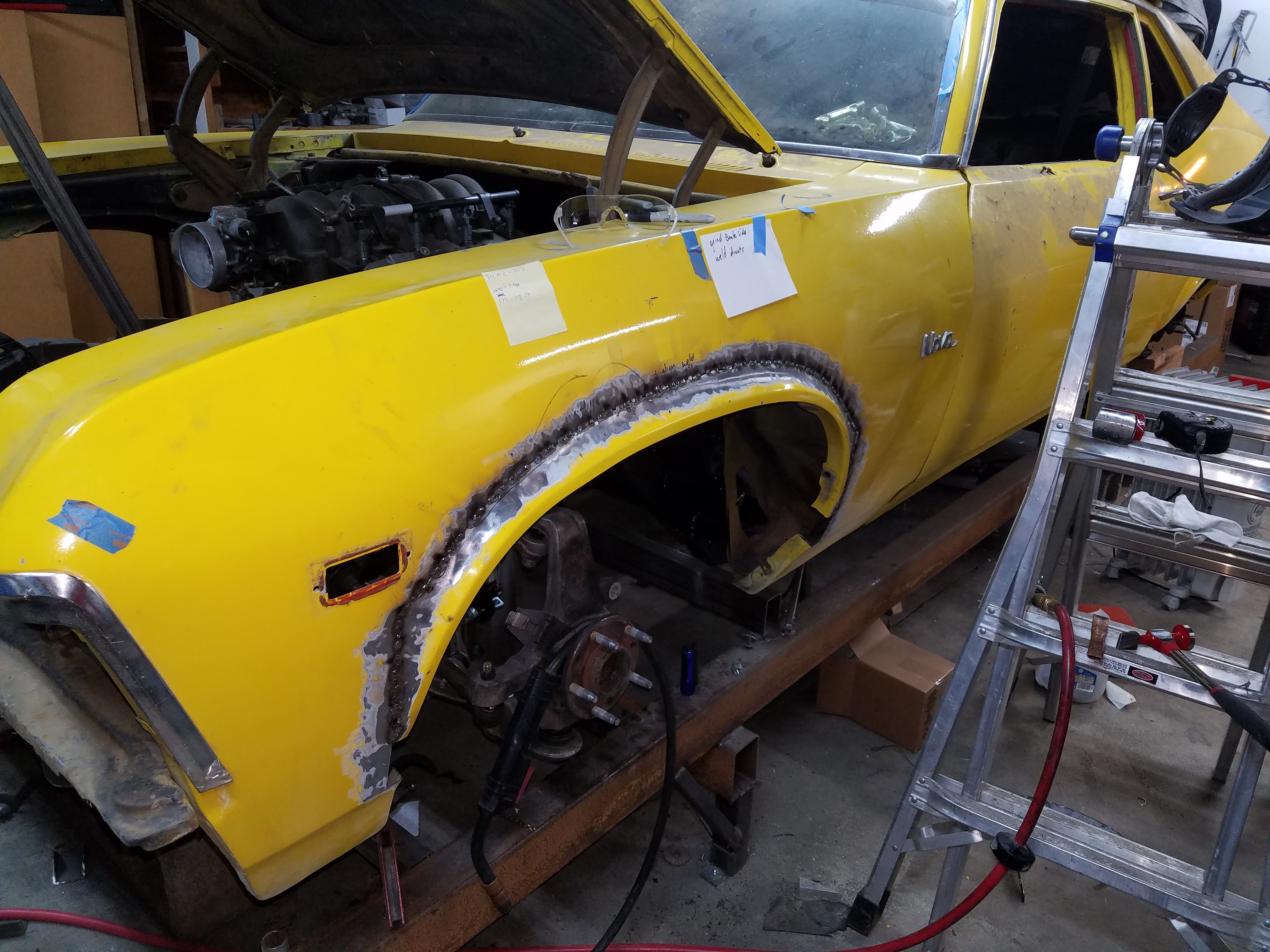
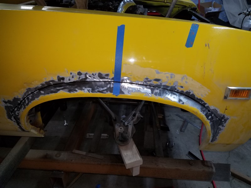
I mocked up the suspension, and couldn't turn the wheel at all. So, borrowing some inspiration from Bouncer's 'Germany Style' nova, and am raising the wheel wells. I'll probably do the same on the back tires.
- - - Updated - - -
Mini update:
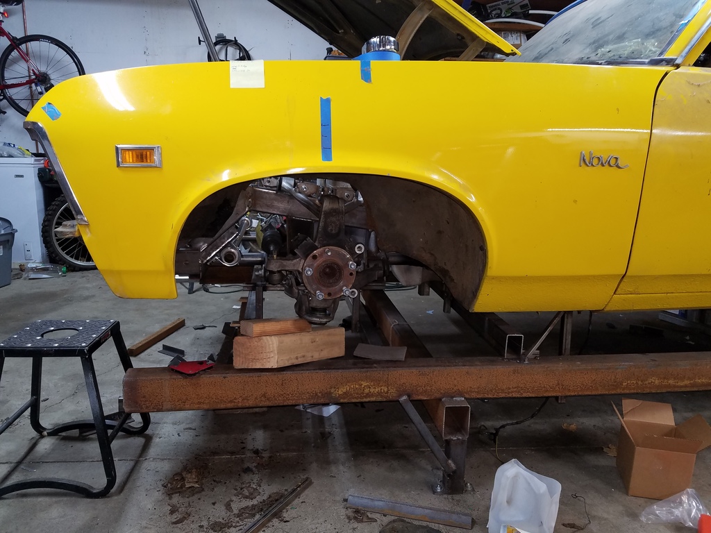
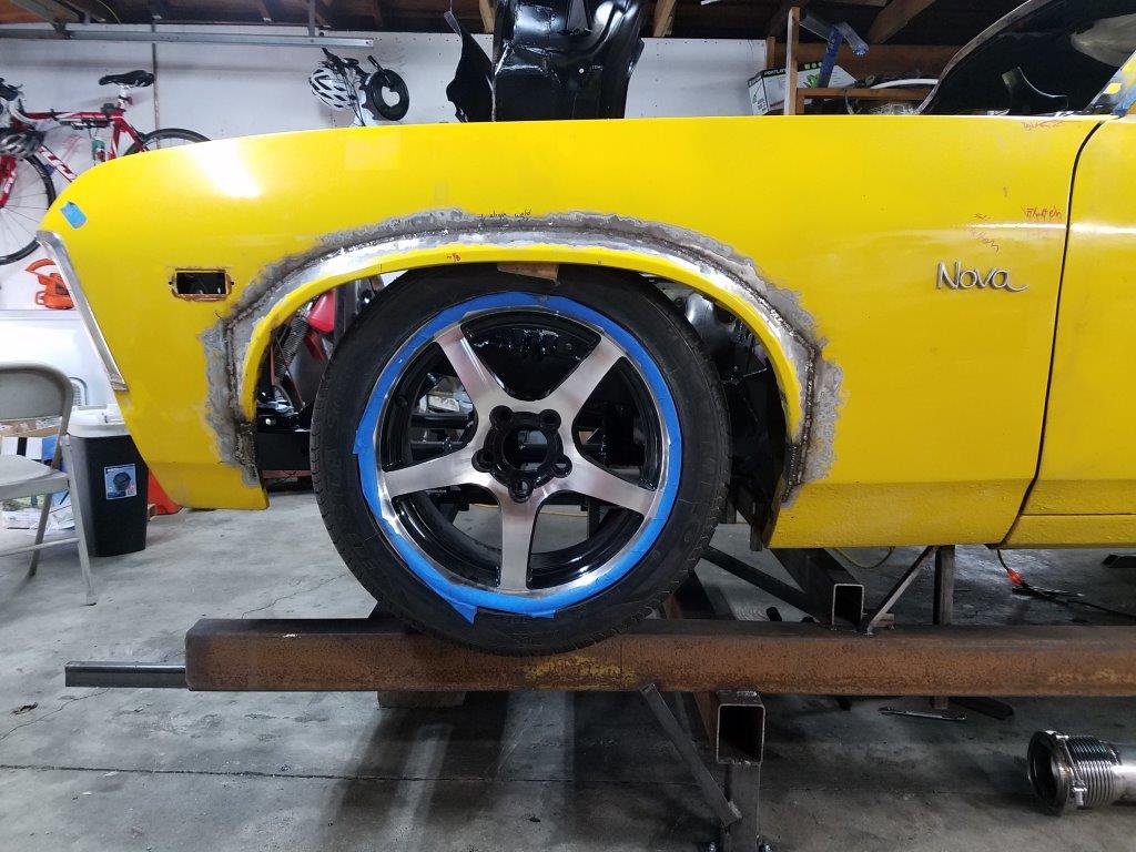
In my last update, I showed the wheel well openings on the front driver side cut out and raised up. In the end, I was able to raise the openings by 2.375" on each side.
Some notes for those who seek to do this:
-There is no vertical portion of the wheel well opening... so when you raise the opening, you end up with a wierd jog. So you have to slice the lower part and re-work it to fix it.
-Cut about 1/4" above where the wheel opening lip meets the main curve of the fender. This lets you work the lip and the main fender curve for a better fit.
-ESAB EZ-Grind wire is worth the cost, if you are mig welding. It hammers out nicely and is relatively soft for MIG wire.
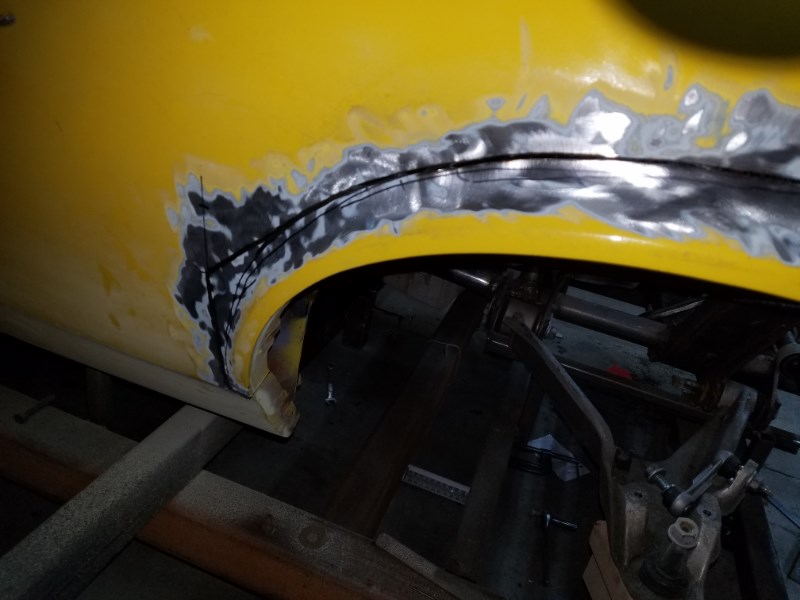
Drive side welded up:
Checking the wheel for clearance, to figure out how to do the inner fender.
This is how/where I cut it on the passenger side.
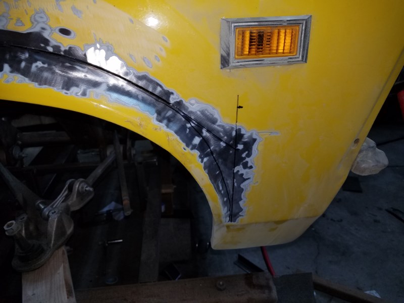
The next step is to rebuild the little brace that the inner fender bolts to, then to modify the inner fender to clear the tires.
- - - Updated - - -
April 2018
Update time!
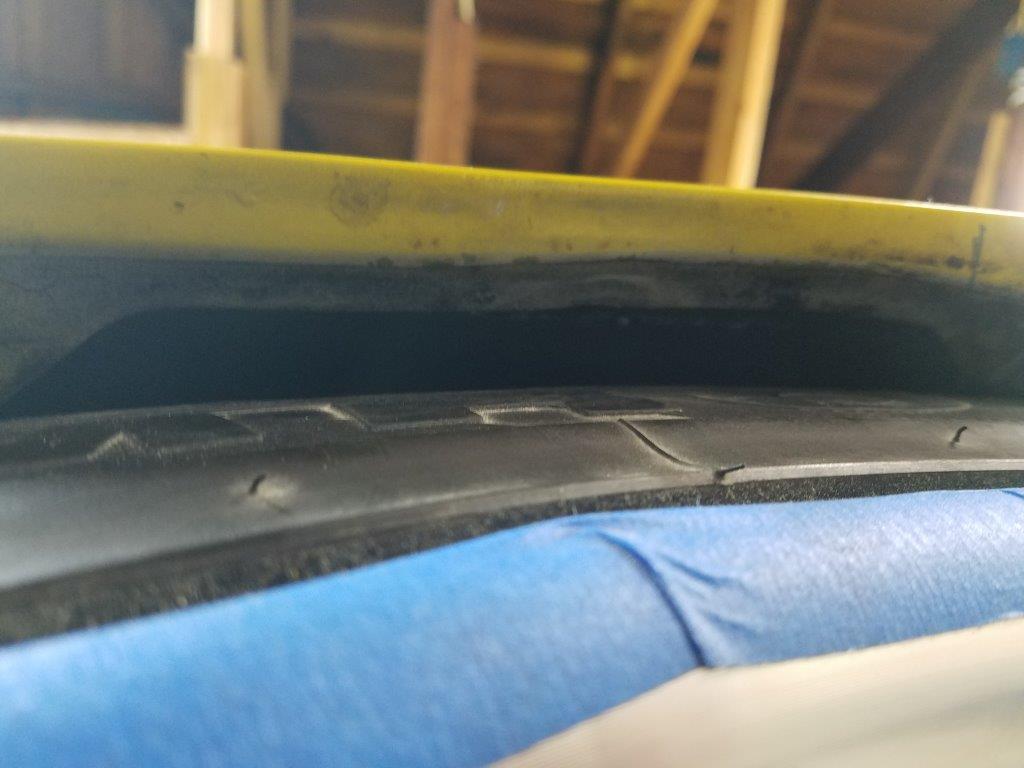
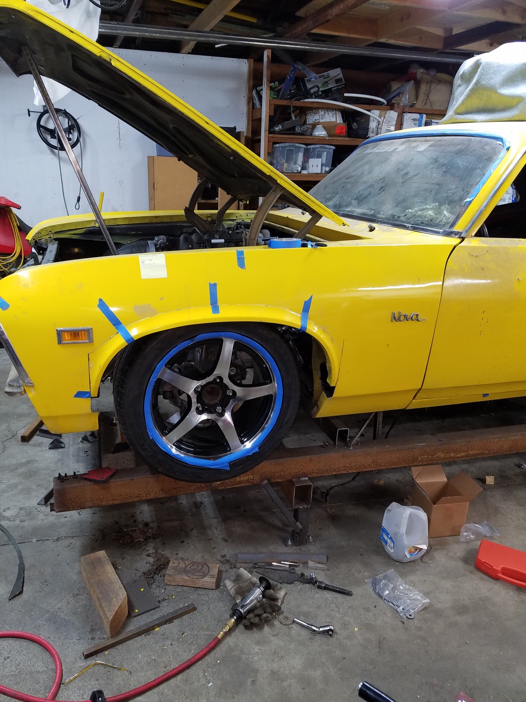
Once the wheel well openings were both raised 2.25 inches, it was time to patch the inner fender together. The photo above shows the clearance I have a 1" of suspension compression.... which is to say, not much. My goal is to have zero rubbing for any wheel position at 1.5" of suspension compression, and have 75% of my steering range at full bump.
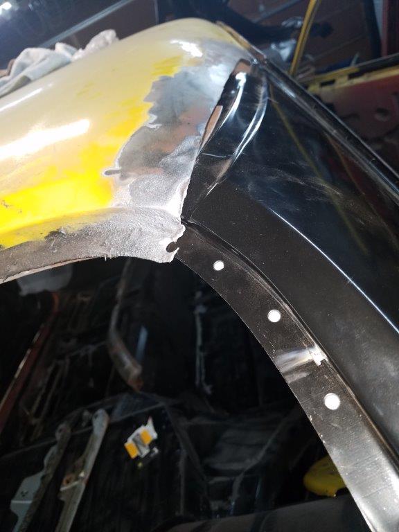
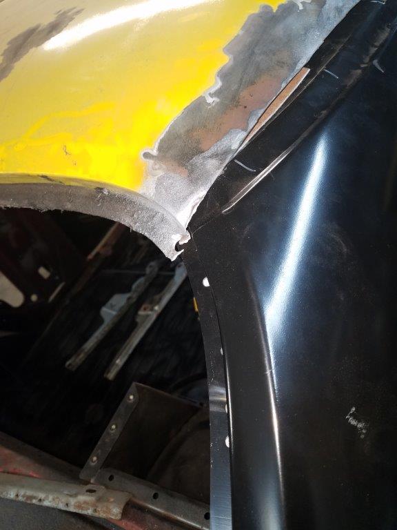
In order to make that happen, I had to cut off the two tabs that held the clip nuts that are at the 10 and 1 positions on the wheel. To replace that, I drilled and tapped some flat stock, and spot welded it to the fender. I then cut the portion of the inner fender off that bolted to the fender opening, and attached it. Then, it was a matter of filling in the gap.
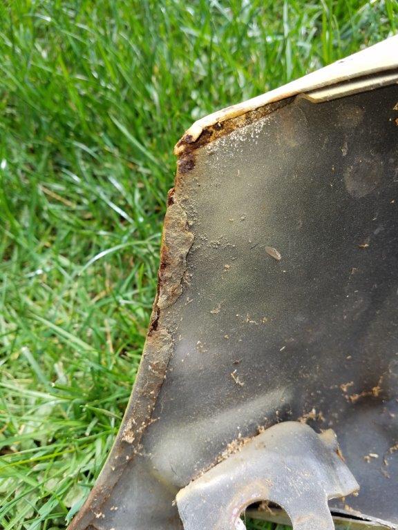
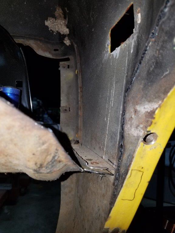
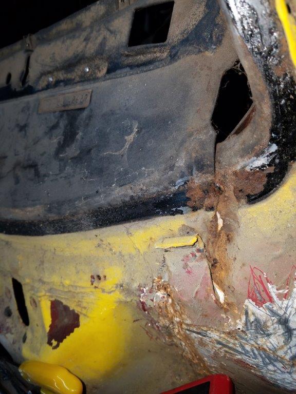
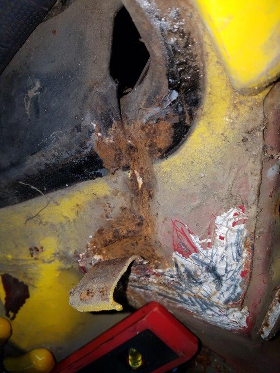
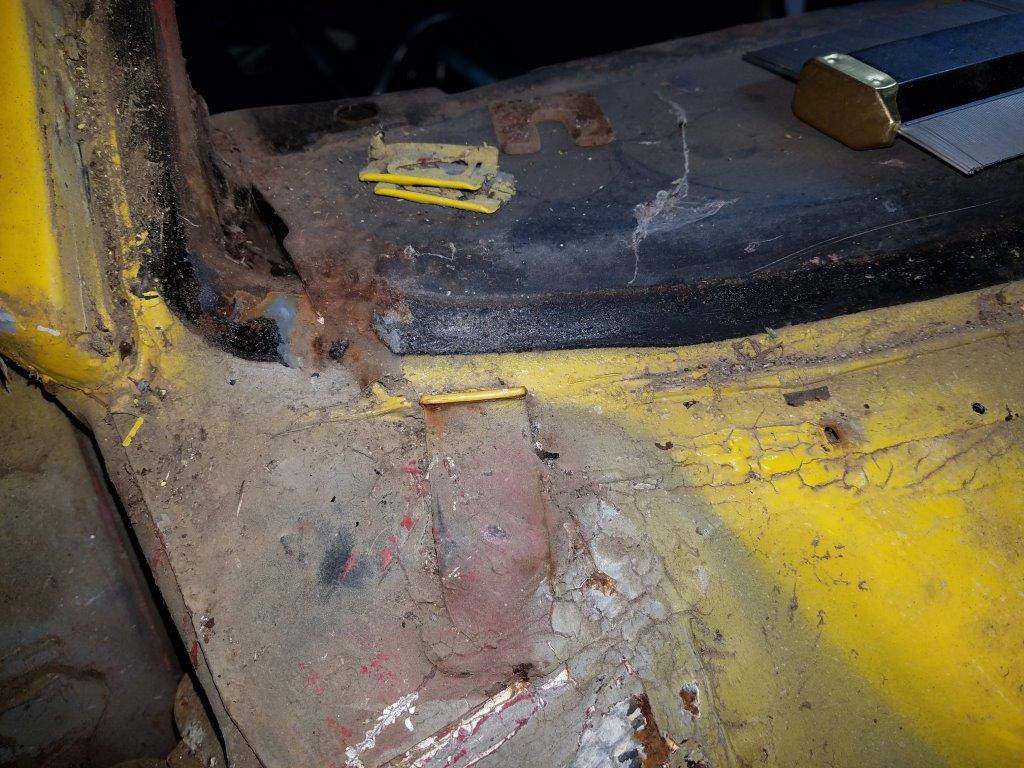
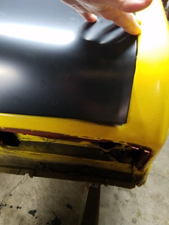
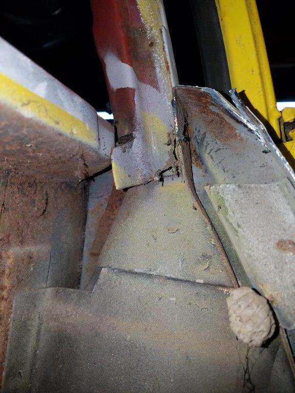
With the inner fenders done, I removed the front fenders and found this rust happening under the window trim. I'm not sure how best to repair this... but I'm going to deal with it later.
Maybe I should just omit the fenders... looks pretty cool!
On to the windsheld wiper motor relocation!
Given how far the motor is recessed into the firewall, the stock wiper motor mount was obliterated. So I read through SevenZeroNova's guide on a relocated wiper motor and purchased a wiper motor and transmission out of a 2001 Pontiac Bonneville.
Motor With Mount plate:
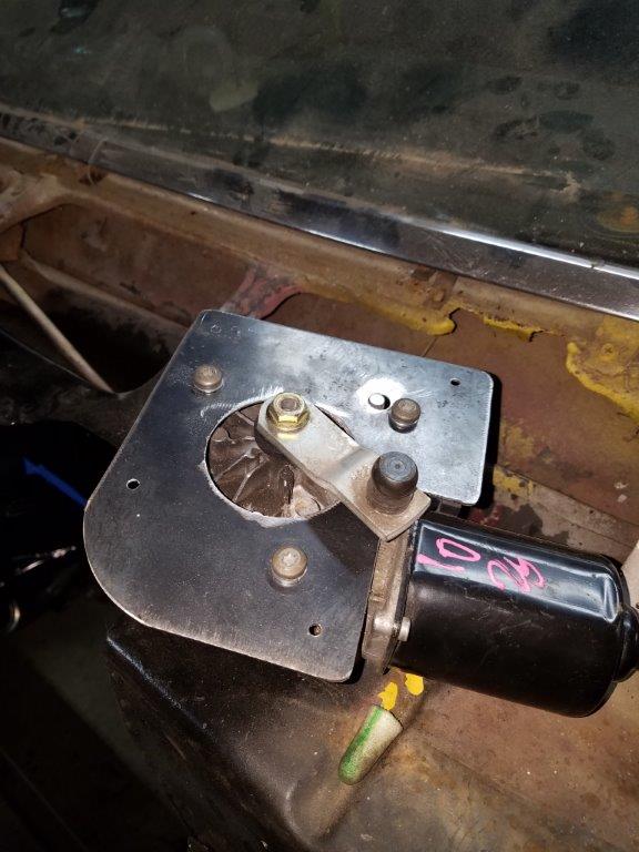
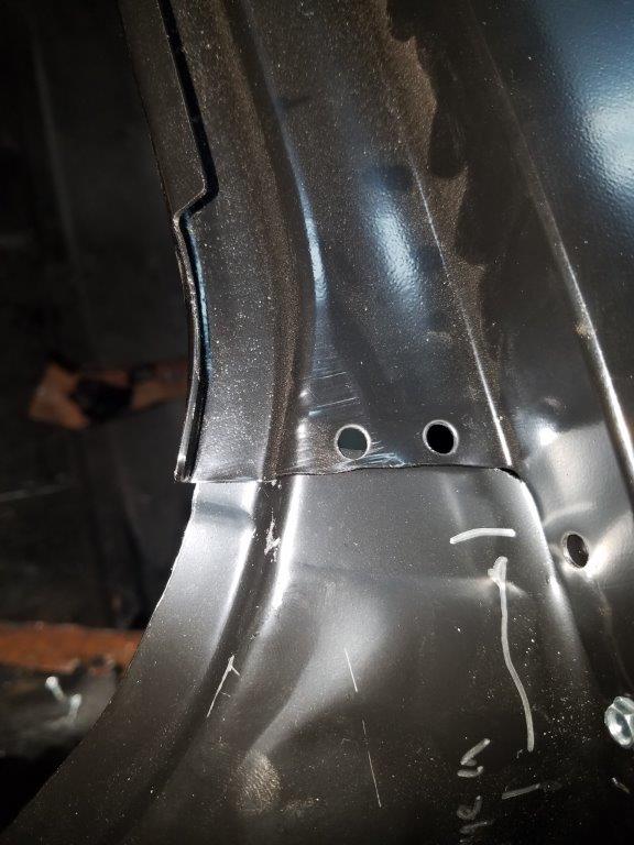
Plate that will weld to the firewall:
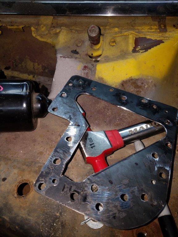
And the hole in the firewall:
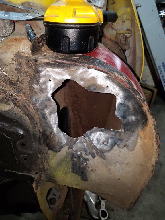
Now, with the motor mounted I ran into a couple of issues. First among these is that there was not a way to run the linkage directly from the motor arm to the middle wiper pivot.
the other issue was that the linkage is worn out.
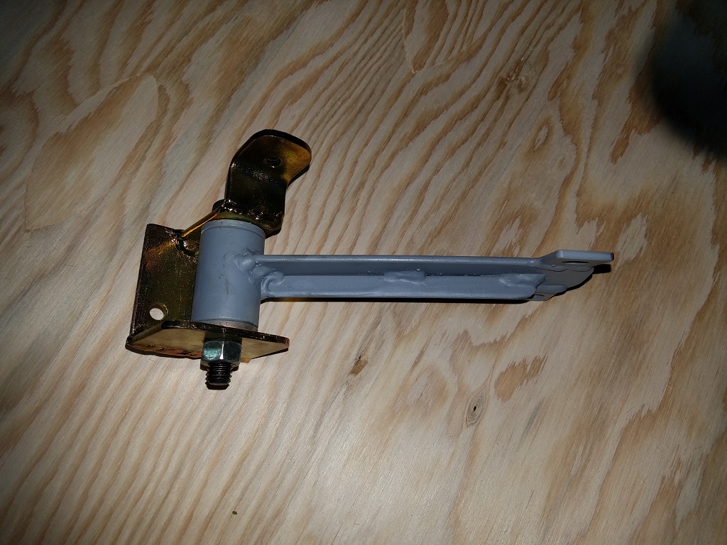
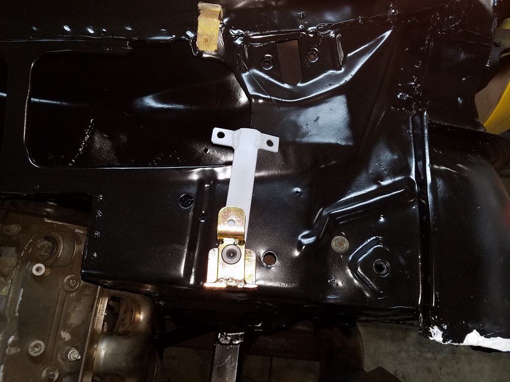
To solve the first issue, I built a pivot arm that bolts to the firewall about where the trim tag goes. The second of the pics below shows about where it installs, but it goes inside the cowl and will barely be visible.
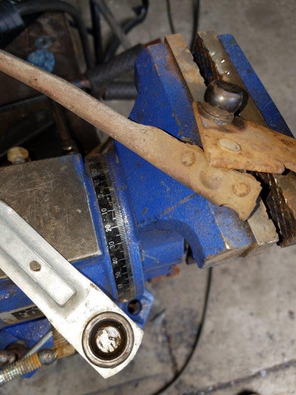
To solve the other issue, I borrowed some more of the Bonneville wiper system. It turns out that if you grind of the riveted in ball studs, the shank is about the same size and offset from the wiper pivot plate. I simply moved the boneville's larger ball stud to the Nova's middle wiper stud's plate... and tacked it in! This works for the linkage that goes from the middle wiper stud to the driver side stud, but you have to cut off the ends of the linkage and weld the Bonneville's in place.
I am waiting on the special bolts that hold the wiper pivots in place. I broke most of mine!
- - - Updated - - -
April 2018
Onward to the dash panel area... turns out I had a little bit of the windsheild corner cancer. There is alot of info on how to fix this. And I didn't take pics of the repair.
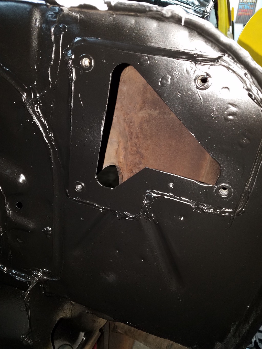
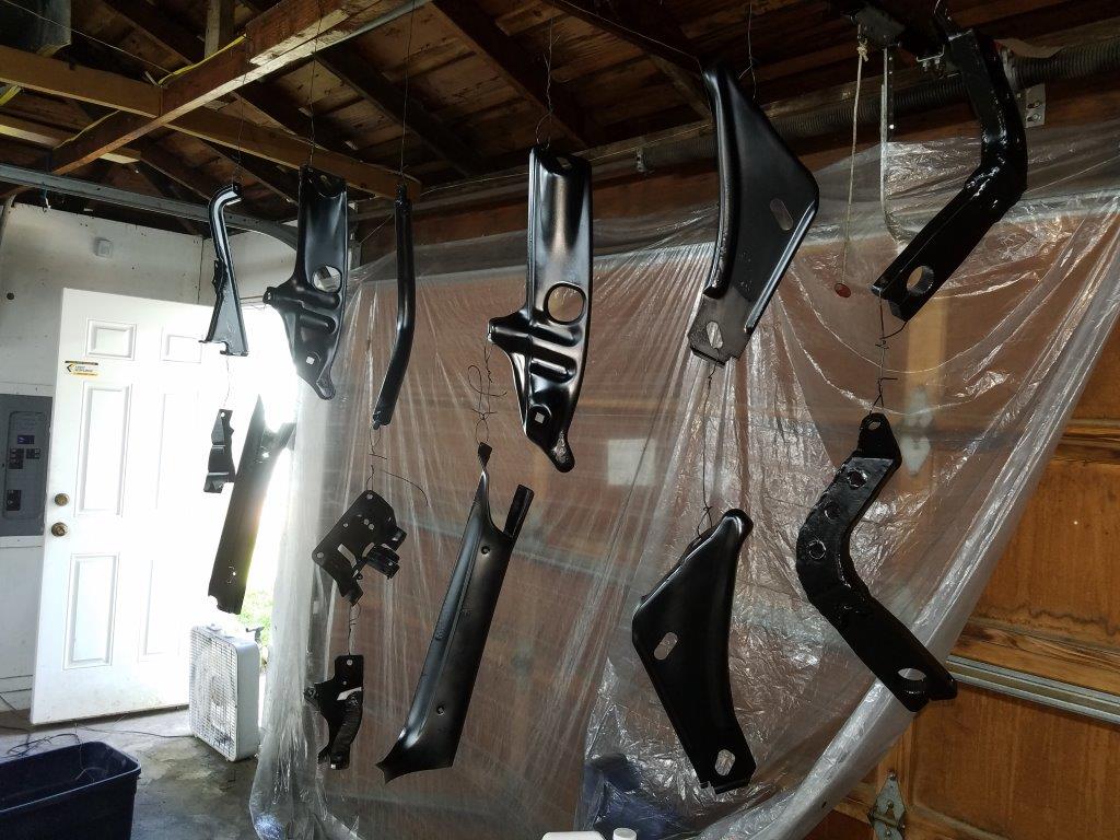
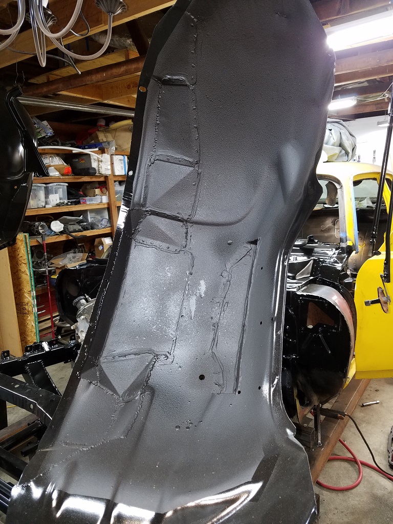
With that done, I took some parts to be sandblasted, and stripped the firewall and front chassis of rust/mill scale and got it ready to primer.
Here it is done!
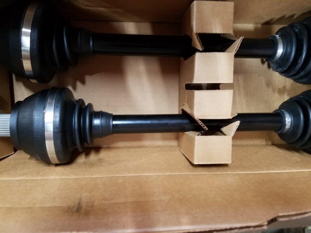
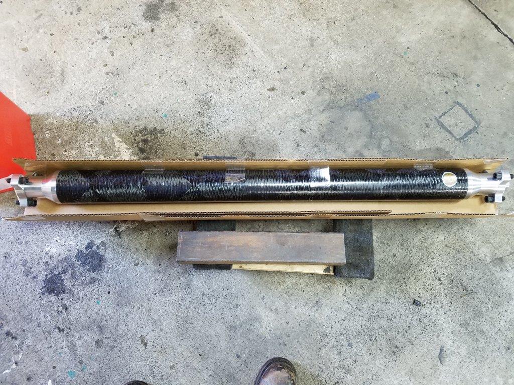
A bit of a tangent... but I had the Drive Shaft Shop narrow up my CV Axles and make a carbon fiber driveshaft for use in the Corvette torque tube! They were 8 weeks in the making, but well worth the wait! After verifying the length, they're going into storage for now.
-
06-27-2018 #4
Registered User
- Join Date
- Mar 2011
- Location
- Portland OR
- Posts
- 26
Update time!
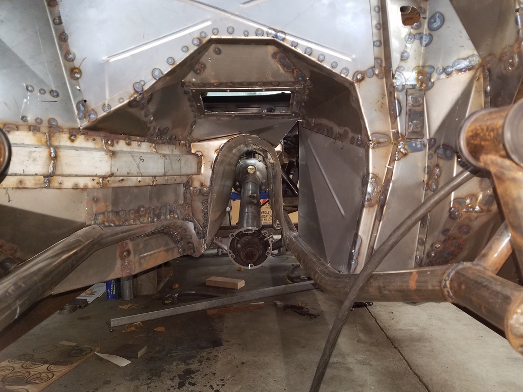
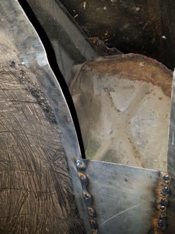
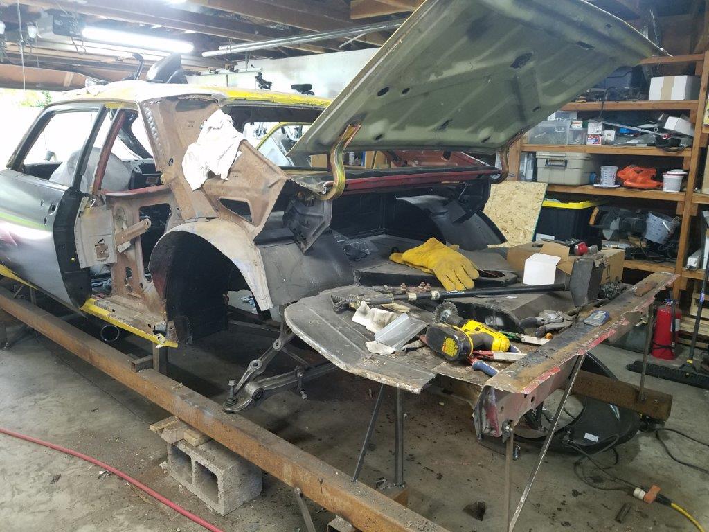
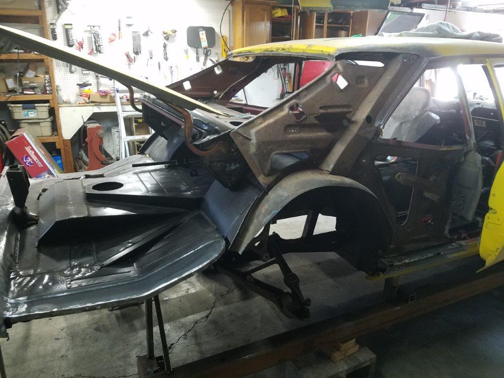
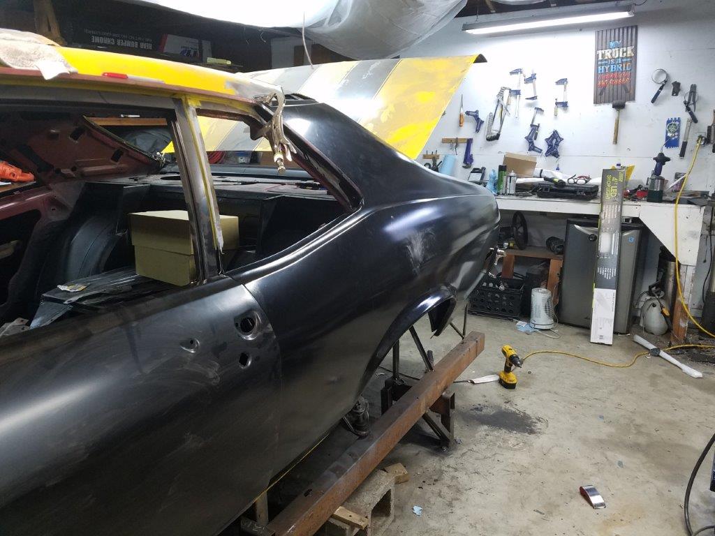
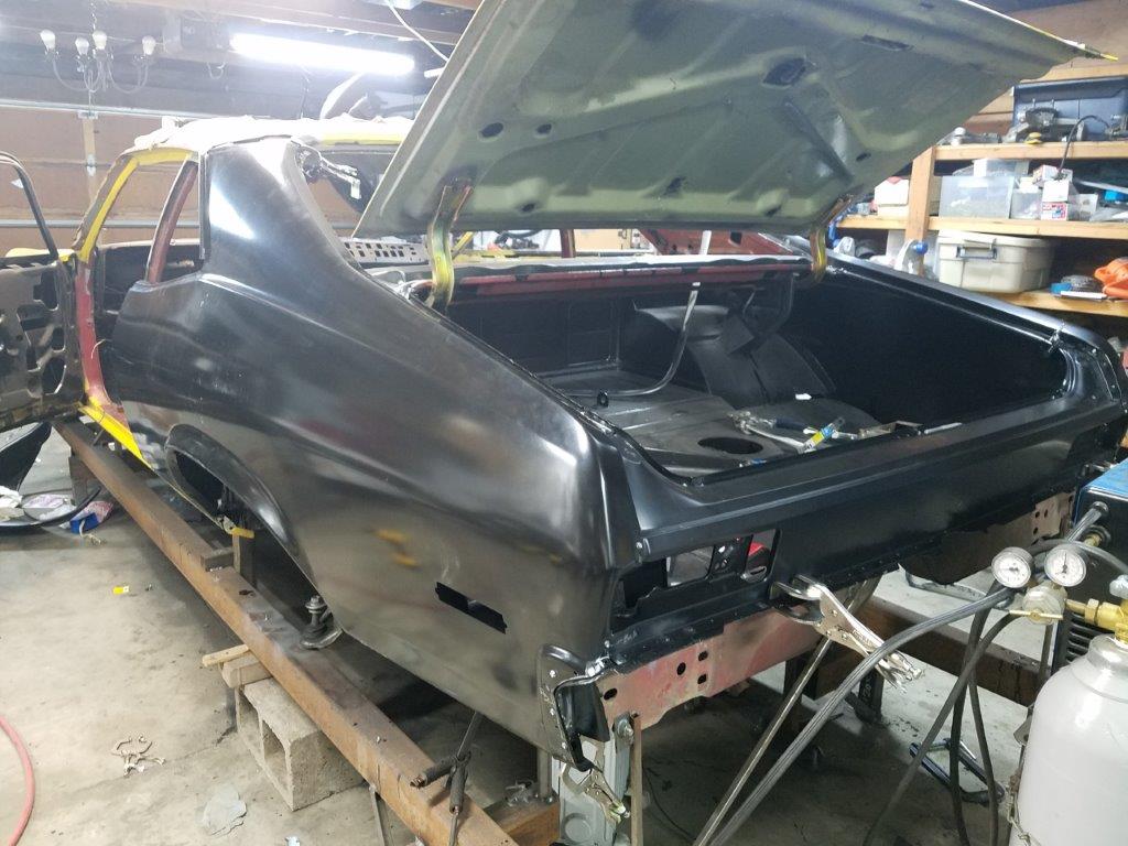
Since my last update, I have been focusing on the rear half of the car again.
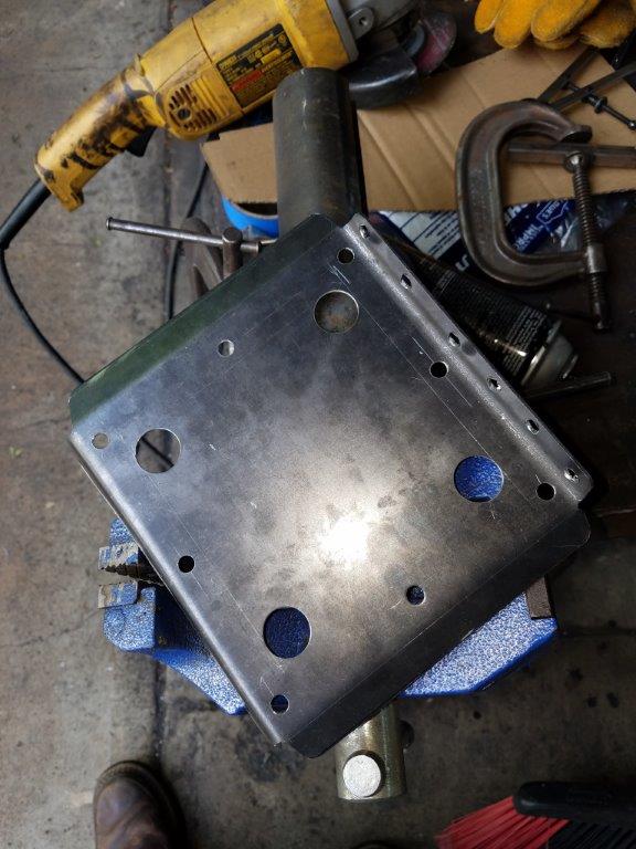
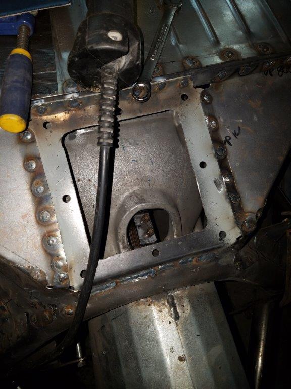
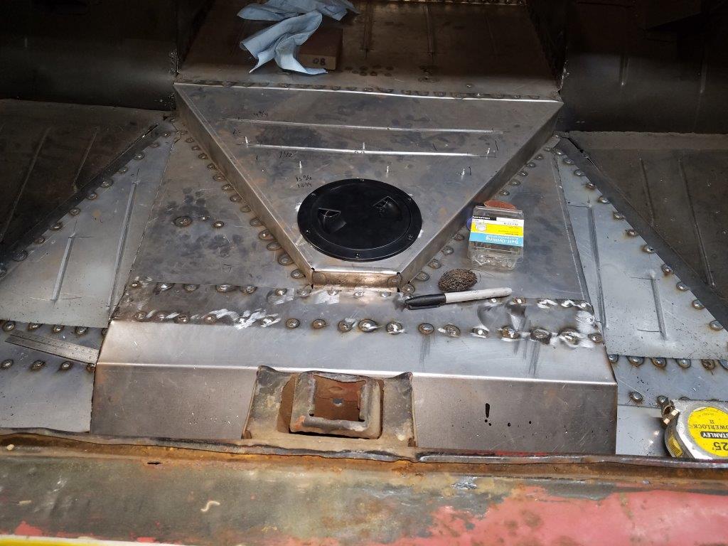
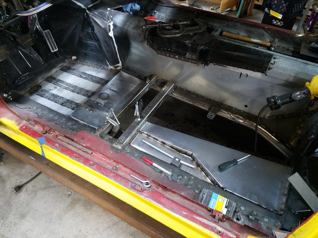
The above photo shows me starting on the access hatch for the rear transmission. This is how I'll get to the shifter linkage to detach it for engine removal.
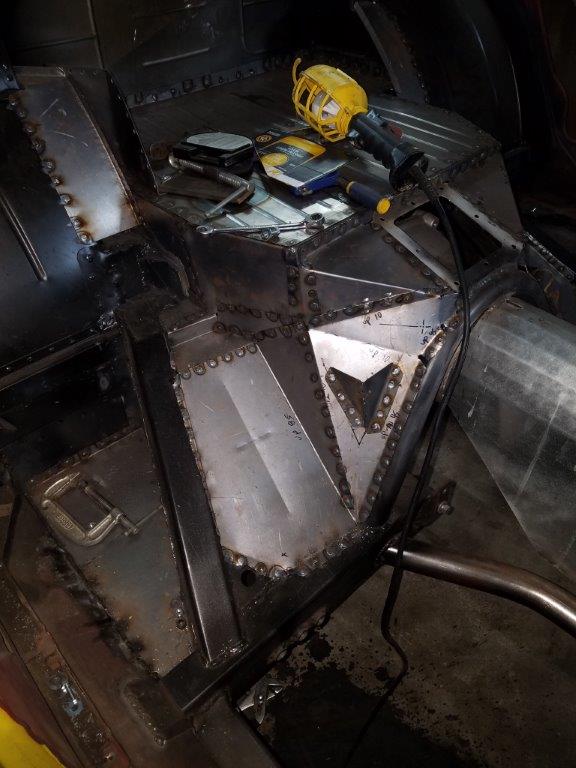
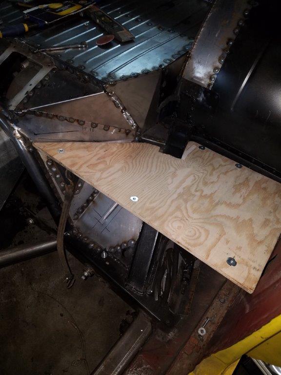
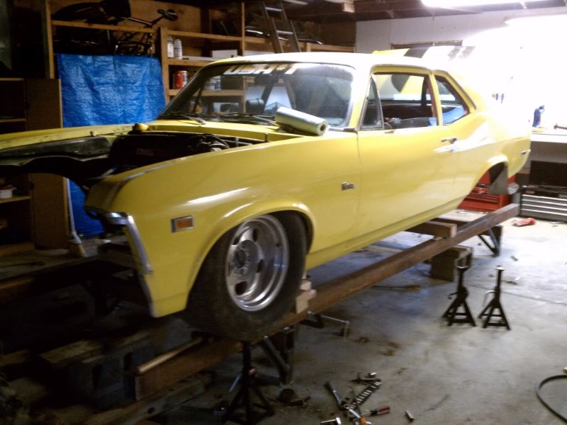
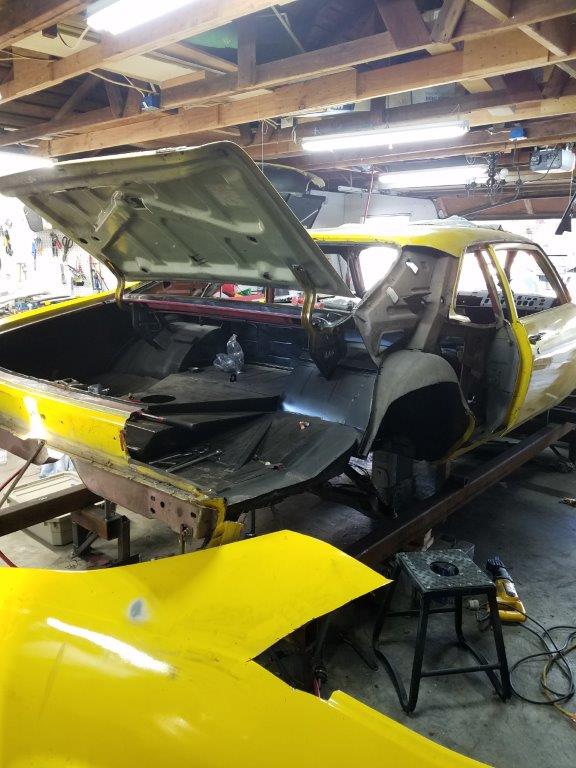
Sometimes you just have to get a glimpse of the end product, right?
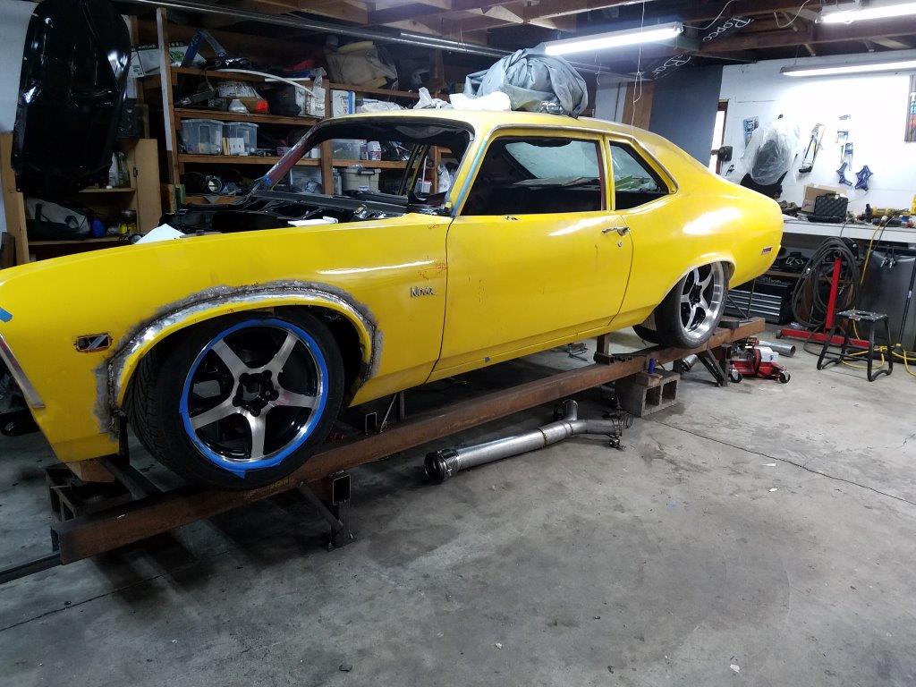
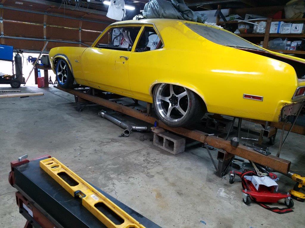
What I leanred by moving the car up like this is that
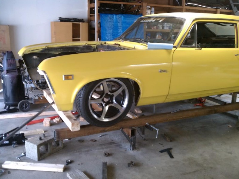
A) A 315/30 rear tire looks disporportionate to a 265-40 front. So I have a 295/40 on the way.
B) Somehow the rear 'axle' centerline got moved forward in the chassis by 1/2". I can align my way out of that, though.
C) I don't have to raise my rear wheel well openings. I think it looks fine like this. I will raise the back by another inch though, to help even it out.
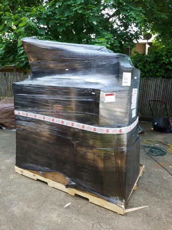
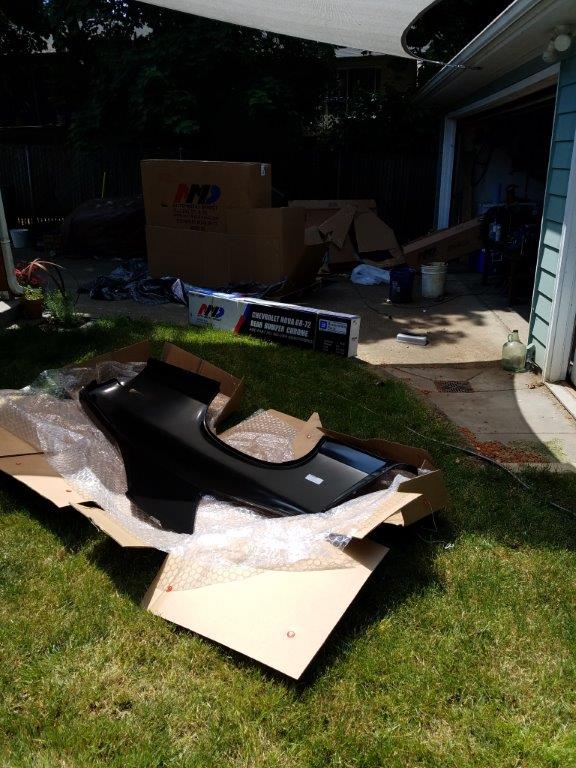
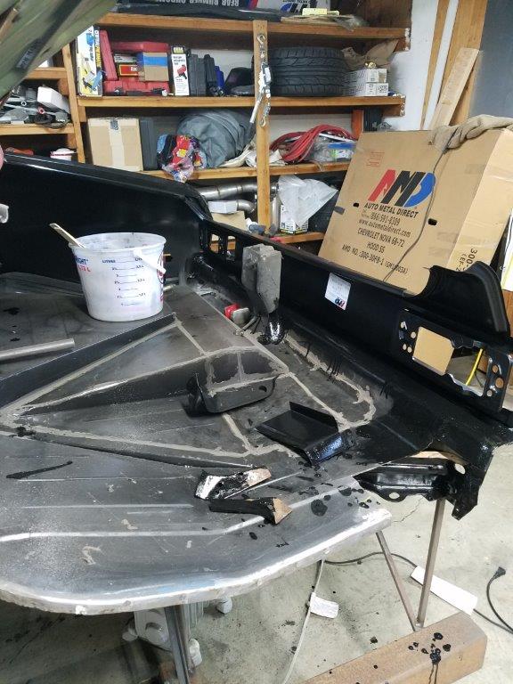
I got my order of sheetmetal! All AMD products.
- - - Updated - - -
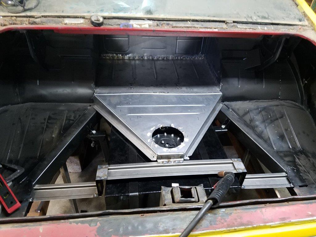
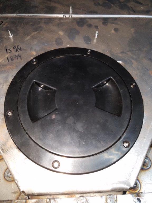
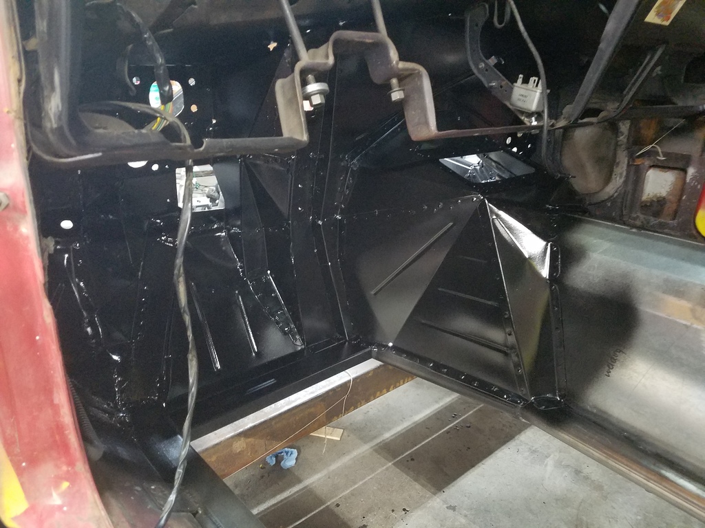
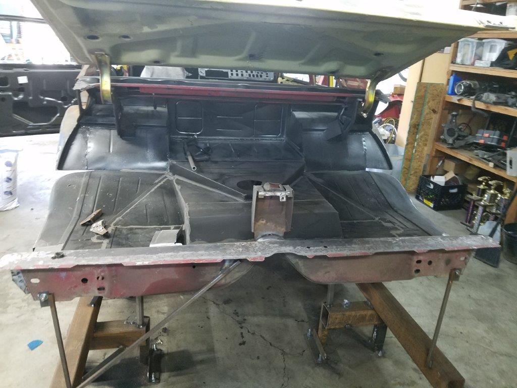
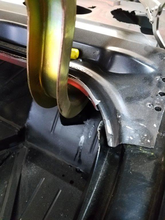
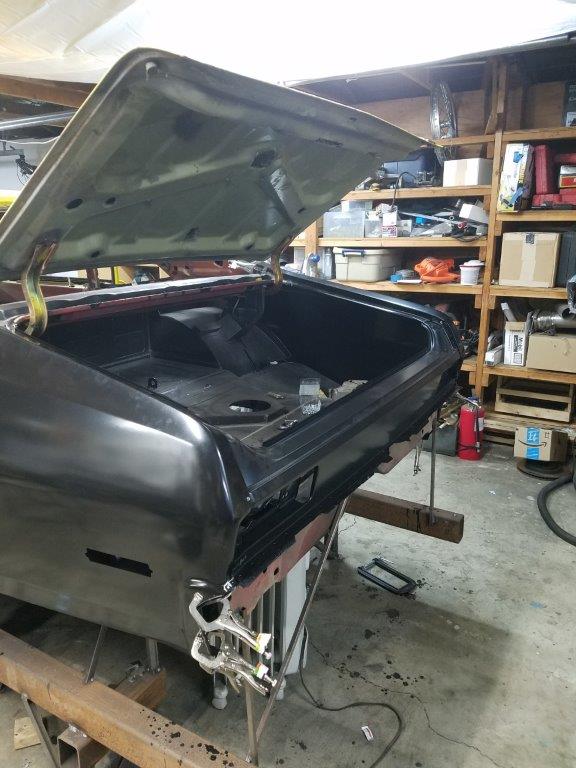
This is the trunk. To keep fumes down, I decided the fuel cell needed to be completely under the floor. The cell was mounted as low as possible, and I bought a thread-in cover with an O-Ring that goes in the trunk floor.
I didn't have the budget for an outside filler neck, so I thought this was a reasonable compromise.
At this point, I'm going to finish the floor boards and seat mounts, then do another round of primer! Then, I'll be going after the rear body sheetmetal.
-
06-27-2018 #5
Registered User
- Join Date
- Nov 2002
- Location
- Georgetown,TX
- Posts
- 2,557
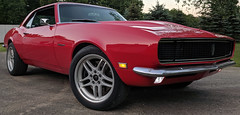
Very nice project you have going on, there. Where did you get the wheels from?
-
06-27-2018 #6
Registered User
- Join Date
- Mar 2011
- Location
- Portland OR
- Posts
- 26
OE Wheels Originally Posted by USAZR1

https://www.oewheelsllc.com/Corvette...-Wheel-Black_6
They're supposedly made with the same tooling as the OEM wheels... so they don't have many BS and wheel pattern options.
-
06-27-2018 #7
Registered User
- Join Date
- Nov 2002
- Location
- Georgetown,TX
- Posts
- 2,557
I thought they looked a lot like C5 wheels but wasn't sure. Really like the look but would have to run 40mm & 50mm spacers. Originally Posted by nickcornilsen
-
06-27-2018 #8
 Registered User
- Join Date
- Nov 2006
- Location
- Ma.
- Posts
- 5,567

Nice work!! I was born 40 years too soon for all that cad stuff. lol It amazes me how this can be figured using it. Keep the updates coming.
Wayne
Car FINALLY home !!!!!! lol
Project FNQUIK https://www.pro-touring.com/showthre...ghlight=FNQUIK
-
06-27-2018 #9
 Registered User
- Join Date
- Dec 2008
- Location
- Detroit
- Posts
- 2,585
One heck of a project! Definitely following along....
Big dreams, small pockets....
Chris--
'72 Cutlass S LSA/T56 Magnum
Bowler Performance, Rushforth Wheels, ATS, Holley EFI, KORE3, Ridetech
Project Motor City Madness
-
06-27-2018 #10
 Registered User
- Join Date
- Dec 2010
- Location
- Charlestown NH
- Posts
- 352
Access to a scan arm is key ey? Imagine modeling that?
Awesome work! i like the torque tube setup, i didnt even think about all the momentum of the driveshaft instead of just the inputhttps://www.pro-touring.com/showthre...-Touring-Truck
DMP Fabrication LLC
Follow me on Instagram for welding and truck progress! - Americangraffiti
-
06-29-2018 #11
Registered User
- Join Date
- Jun 2012
- Location
- Chicago burbs
- Posts
- 247
Wow, the use of the waterjet and all the CAD is awesome! makes things so clean and predictable. I also like how you digitized parts of the car to get a real accurate mockup. Did you use the CMM for that? I've recently tried photogrametry through Autodesk/ Fusion360 which is amazing and free, but aside from digitizing the front end of my G8GT and my shifter console, I haven't done much with it. Anywho, love the project man, very rare does a project like this actually make such good progress. Keep it up.

1969 442 6.0L LQ9 T56
Fab9 w/ custom 3 Link conversion
FAYS2 Watts link
Thanks to Mark at SC&C for his honesty and passion for the sport, and Ron Sutton for the wealth of knowledge that has helped shape so many of the cars on this site.
-
06-30-2018 #12
Registered User
- Join Date
- Jan 2018
- Location
- Oregon
- Posts
- 40
Holy cow this is an amazing build. I am from the area and will have to see this when it is done. In comparison it makes my work look like a child's. I have been procrastinating with my body work because I am so afraid I will mess it up (I need to replace floor boards, tail panel and trunk plus have mini tubs sitting on my shelf).
Also all of these yellow novas make me reconsider trying to save my original shadow grey patina.
-
06-14-2019 #13
Registered User
- Join Date
- Mar 2011
- Location
- Portland OR
- Posts
- 26
So shortly after my last build update, a big life even occurred for my family!
She was a bit early... 10 weeks to be exact. Looking back, its shocking how small she was, but one by one, all of the risks and potential issues went away.
She was a willful little thing, deciding she no longer needed respiratory assistance 2 weeks before the doctors said she could come off of it. (She ripped it off in the night,
and her vitals never missed a beat. Still, we were in NICU jail for 6 weeks. It was a stressful time that certain put some things into perspective.
She's coming along fine now. She seems to be showing an interest in tools!
Anyway, I was able to get an hour or two here and there, and finished the trunk and floor pans.

At this point I primered and seam sealed the trunk and the floor, however I did not get pictures of that freshly done. I also didn't get any pics of replacing the
deck filler panel. The AMD panel I got did not fit AT ALL. The radius of the arch in the panel was about 1.5" off in the middle, and there were no releifs for the trunk hinge
bodies. I got a Golden Legion panel, and it dropped right in.
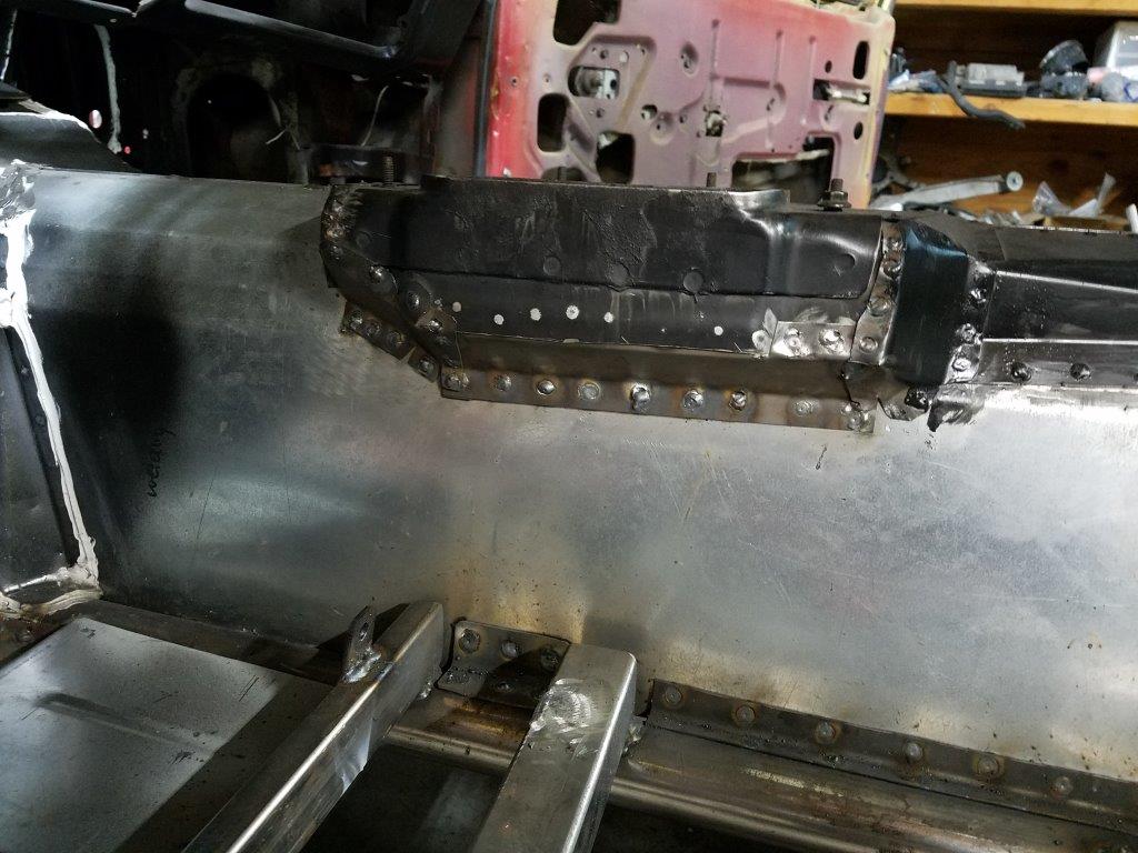
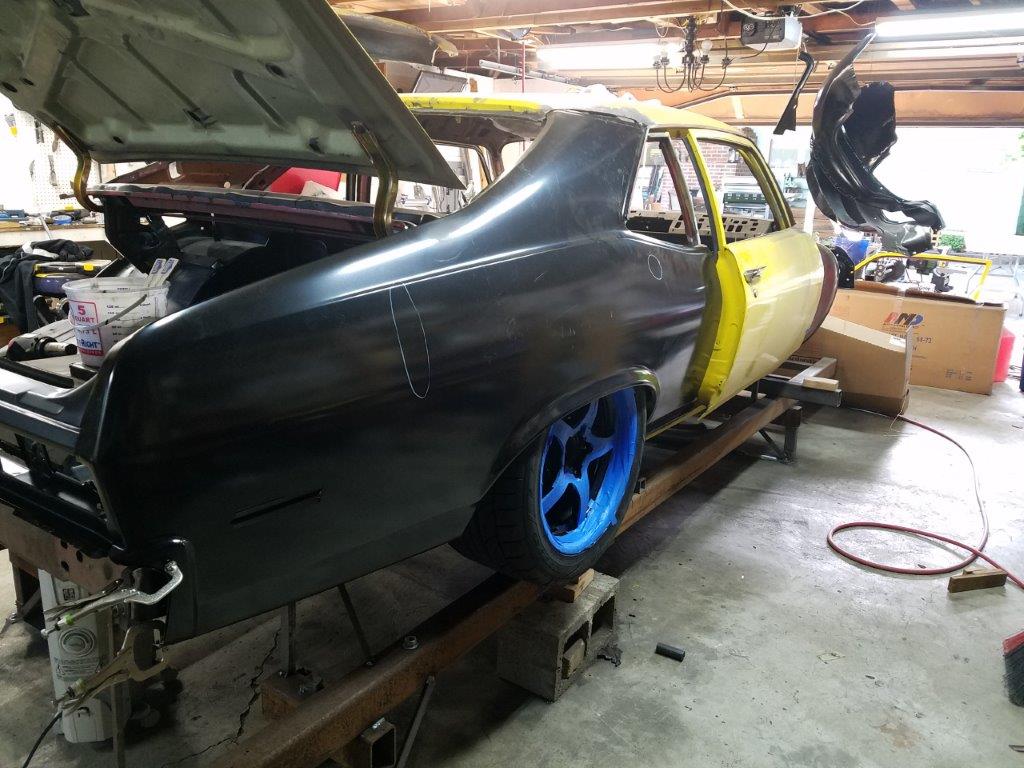
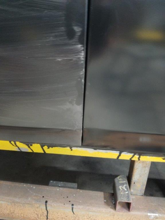
On to the quarter panels. I thought I'd see how the AMD repop trunk fit. Answer: Not good. The counters were not right, the mount points seemed to be offset
to the right by 3/4". It is savable, but I decided to put the stock trunk on as an alignment tool for the quarter panels.
Sawzall time!
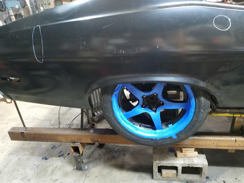
Tire fitment Check:
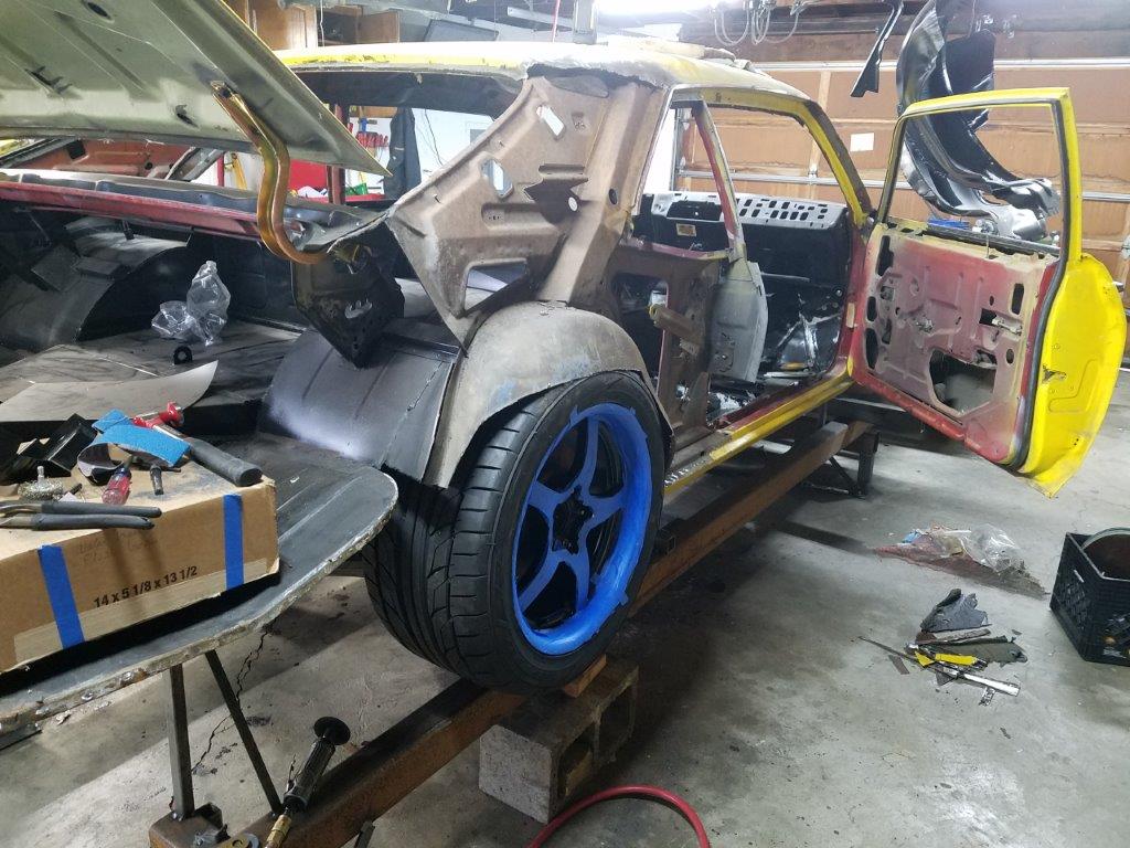
Driver's side:
All cleaned up and ready for primer
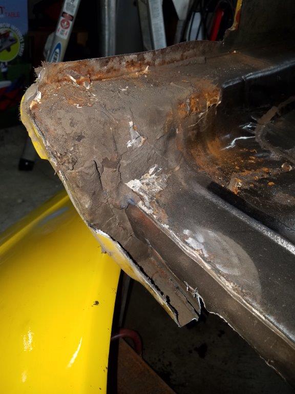
I had a little bit of rust that needed repaired on the driver rear corner of the trunk pan.
- - - Updated - - -
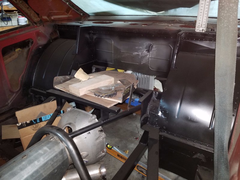
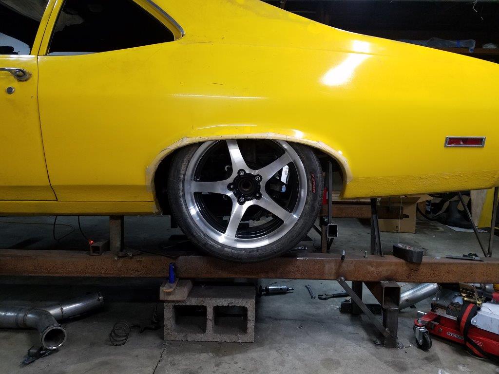
Tire mocked up. The steel beam the tire sits on represents a 1.5" of wheel compression upwards. I am going to install the QPs without the inner wheel well, and will hand-fab a new one
that gives me more tire clearance after the panels are installed.
I had always heard AMD panels were the best. I question that now, at least for Novas. I actually wondered if someone ripped me off and put another brand
of panel in an AMD box. Nope, the second set of AMD panels I bought from Summit were identical. Maybe I'm too picky, but I have about 4 hours into each panel for fitting, and
will have a few more for some post-install adjustments.
Fitment was OK at the top. comparing to the trim piece, the contour is correct.
However, the Pass side trunk rail was stamped 5/8"of an inch to far forward on the panel. That caused fitment problems at the tail panel and at the front, where the deck filler lays into it.
I also had to spent a bunch of time rolling the trunk gasket rail upwards, and tightening the trough that the trunk weatherstrip goes in. It is still about 1/8" too wide
compared to OEM, but it will hold the weatherstrip now. A little adhesive will make sure it stays.
The driver side panel had the same issue with the shape of the trunk weather strip, but at least it was in the right place.
Not to say the driver side QP didn't have it's issues. It seems that the flange on the bottom of the panel was stamped 3/16 too far forward. Once welded on, I will slice into the
QP to widen the door gap, and move the back edge closer to the rocker panel.
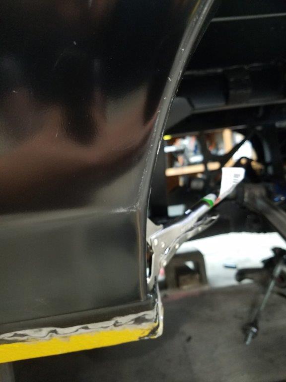
I also had to slice and dice the top area of the panel to make it fit into the B-pillar. I also needed to hammer the pinch weld flange back about 1/4" in the middle to make it align
with the inner QP piece. Both side QPs also had the door latch peg hole in the wrong place.
The AMD tail panel, however, fit PERFECT. I adjusted NOTHING on it. Same goes for the pieces that go in the corner where the QP meets the tail panel.
I was in the shop until 10PM last night doing the first round of welding. It's exciting to see the new QP's on!
The next steps are to build the wheel housings to clear the tires... then I might cut the car free of the chassis jig for the first time since 2011!
-
06-14-2019 #14
Registered User
- Join Date
- Nov 2006
- Location
- Ma.
- Posts
- 5,567
First so happy to hear your little girl is doing so well! Those NICU people are great.
Nice update it looks good all mocked up. Glad your getting some time to work on it.Wayne
Car FINALLY home !!!!!! lol
Project FNQUIK https://www.pro-touring.com/showthre...ghlight=FNQUIK
-
06-14-2019 #15
Registered User
- Join Date
- Jun 2012
- Location
- Chicago burbs
- Posts
- 247
Tried a couple of times to write a response, guess I'll just say I'm real happy for you and your family. Before you know it you'll be looking for a project car for you and her to build.

Still a big fan of your work, now more than ever.
1969 442 6.0L LQ9 T56
Fab9 w/ custom 3 Link conversion
FAYS2 Watts link
Thanks to Mark at SC&C for his honesty and passion for the sport, and Ron Sutton for the wealth of knowledge that has helped shape so many of the cars on this site.
-
06-18-2019 #16
 Registered User
- Join Date
- Aug 2007
- Location
- Denton Texas
- Posts
- 1,236
this is a very cool project...
-
06-18-2019 #17
 -Moderator/Sponsor-
- Join Date
- Apr 2001
- Location
- The City of Fountains
- Posts
- 15,975
Man, what a project! Awesome.
Andrew
1970 GTO Version 3.0
1967 Cougar build
GM High-Tech Performance feature
My YouTube Channel Please Subscribe!
Instagram @projectgattago
Dr. EFI
I deliver what EFI promises.
Remote Holley EFI tuning.
Please get in touch if I can be of service.
"You were the gun, your voice was the trigger, your bravery was the barrel, your eyes were the bullets." ~ Her
-
06-24-2019 #18 Registered User
- Join Date
- Sep 2009
- Posts
- 2,707
Wow, the fab work on this is outstanding!
1955 Nomad project LC9, 4L80e, C5 brakes, Vision wheels
1968 Camaro 6.2 w/ LSA, TR6060-Magnum hybrid and etc SOLD
1976 T/A LS1 6 Speed, and etc. SOLD
Follow me on Instagram: ryeguy2006a
08-03-2019 #19 Registered User
- Join Date
- Oct 2015
- Posts
- 122

Looking good. Also like what you did to the front wheel openings. How much clearance did you gain? Keep up the great work and design.
08-03-2019 #20
Registered User
- Join Date
- Nov 2018
- Location
- Oregon
- Posts
- 230
Not sure how I missed your build thread but it is a great read thank you! There seems to be a lot of major metal fab projects here in Oregon and it is awesome!
Tags for this Thread

 Reply With Quote


