Results 1 to 11 of 11
-
11-26-2017 #1
 Registered User
- Join Date
- Oct 2011
- Posts
- 696
Mercedes Headlight Switch in Camaro
Hey guys trying to use a Mercedes rotary style headlight switch in my 69 Camaro. I was hoping to just put the voltmeter into continuity mode and find wires that complete the circuit but no luck. I am getting some readings in continuity mode they are:
1 click right (all lights on) .121 between pin 8 and 6
vertical (auto) .590 between pin 8 and 6
1 clock left (I think thats for parking lights on) .121 between pin 8 and 7
I have very basic electrical knowledge hence I dont understand whats going on or how I can make this work. But Im pretty sure pin 8 is ground.
Im attaching a wire diagram I found of a similar switch maybe you guys can make sense of it.
Basically I want all lights off in vertical position (auto), all lights on in (1 click right position) and parking lights on in (1 click left position).
Thanks!
-
11-26-2017 #2
Registered User
- Join Date
- Oct 2011
- Posts
- 696
Here is link to wiring diagram pics are horrible:
https://mbworld.org/forums/attachmen...car_328745.pdf
-
11-26-2017 #3
 Administrator
- Join Date
- Jan 2000
- Location
- Thousand Oaks California
- Posts
- 10,031

Oh cool! I hope you figure this out. I've always wanted to do something like that.
Larry Callahan
Founder/Administrator of Pro-Touring.com, G-Machines.com and HostMyJunk.com
To advertise on Pro-Touring.com click here
-
11-26-2017 #4 Registered User
- Join Date
- Jun 2014
- Posts
- 177

It's hard to read those drawings without a sort of legend. My guess would be that pin 4 is your power, as that's fused with F5. The ground....Pin 3 or 8 if I had to guess as it's also 0.5 in size (same as power). But they reference the grounding point on the head lights as going into an LWR connection which is what Pin 3 is labeled. The other pins go into a "Transistor Board" of some sort. They might need to have power applied and it might send base current to a transistor in that board above based on where the switch is / what button is pressed. The lights in a benz are most likely controlled by a BCM computer in the car.
I would think you need power on that switch to get proper readings, try referencing pins to pin 8 or pin 2 and see what you get. Does Pin 2 react when you press the fogs lights button?
The more you look at those drawings the harder it is to figure out haha.Last edited by Jerems; 11-26-2017 at 05:44 PM. Reason: Found something on the ground wiring.
11-26-2017 #5
Registered User
- Join Date
- Oct 2014
- Location
- DFW, Texas
- Posts
- 422
This is going to be a bit more complicated than I believe you think it is.
The "auto" feature is reliant upon a ambient light sensor, which is typically located in a rearview mirror and is monitored via a local module. Like a sunroof module, it's status [light/dark] would be communicated via CAN to a body control module. The headlight switch you have essentially has no mentionable current going through it [nor should it], it provides a very small input to another module to let it know the intent, it may even be on a LIN-bus, between some smaller components.
At a quick glance, I don't believe your diagrams show enough detail of the other components tied to it.
If I were to take this on, I would take down what inputs you know and plan on interfacing an Arduino controller to interpret the switch positions and control the relays you need. You can also add a light sensor to the Arduino for the "auto" mode to actually work, given you code in some sort of delay. You could also try to gut it and put a 3-positon switch rotary switch behind it [think wipers] to get it to have basic positions to get what you want out of it...1972 Plymouth 'Cuda - Not LS-swapped, 5.7L Hemi [MS3 Gold Box], T56 Magnum 6-speed - 'Cuda Build Page
1976 Dodge D100 - Warlock
2016 Subaru WRX - E30 Tune
11-27-2017 #6
Registered User
- Join Date
- Oct 2011
- Posts
- 696
Talk about over complicating a simple switch, wow! I'm definitely not tech savvy enough for an arduino. I believe between pin 8 and 2 only when you press the fog light button I got a current of .5 (again when in continuity mode).
Here's what I was thinking maybe you guys can tell me if this will work or not. So I hook up pin 8 to ground and pin 6 to constant 12v, then run wire from pin 6 to relay to power the headlights. When I turn the switch from auto to the right it should send some current to the relay which will excite it to turn on the headlights. To turn off, I turn left to auto which will excite the relay again and relay will turn off lights. I need constant 12v at the switch because if I have power only during ignition it will excite relay and lights will come on when ignition on. The only drawback I see to this is that I will always have to remember to turn off lights before exiting vehicle.
After looking at my AAW kit I see there are several more wires that feed into the headlight switch red, dk green, orange, brown, white, yellow. What would I do with all these wires? I'm assuming red is 12v, brown is ground. Here are the schematics for the kit.
https://www.americanautowire.com/PDF...20IN%203.0.pdf
11-30-2017 #7
Registered User
- Join Date
- Oct 2011
- Posts
- 696
What do you guys think about my idea of connecting relay to pin 6?
11-30-2017 #8 Registered User
- Join Date
- Nov 2011
- Location
- Wylie, Texas
- Posts
- 279
I think it's a bad idea. From the schematic you can tell that this switch was not designed to handle much current and it may not even be rated for 12v either. I would keep the voltages 5V or under and limit current to 10mA or below to prevent damaging this switch pod. Of course you're welcome to try anything you want, just be sure to take video and post the results

12-01-2017 #9 Registered User
- Join Date
- Apr 2006
- Location
- Atlanta, GA
- Posts
- 128
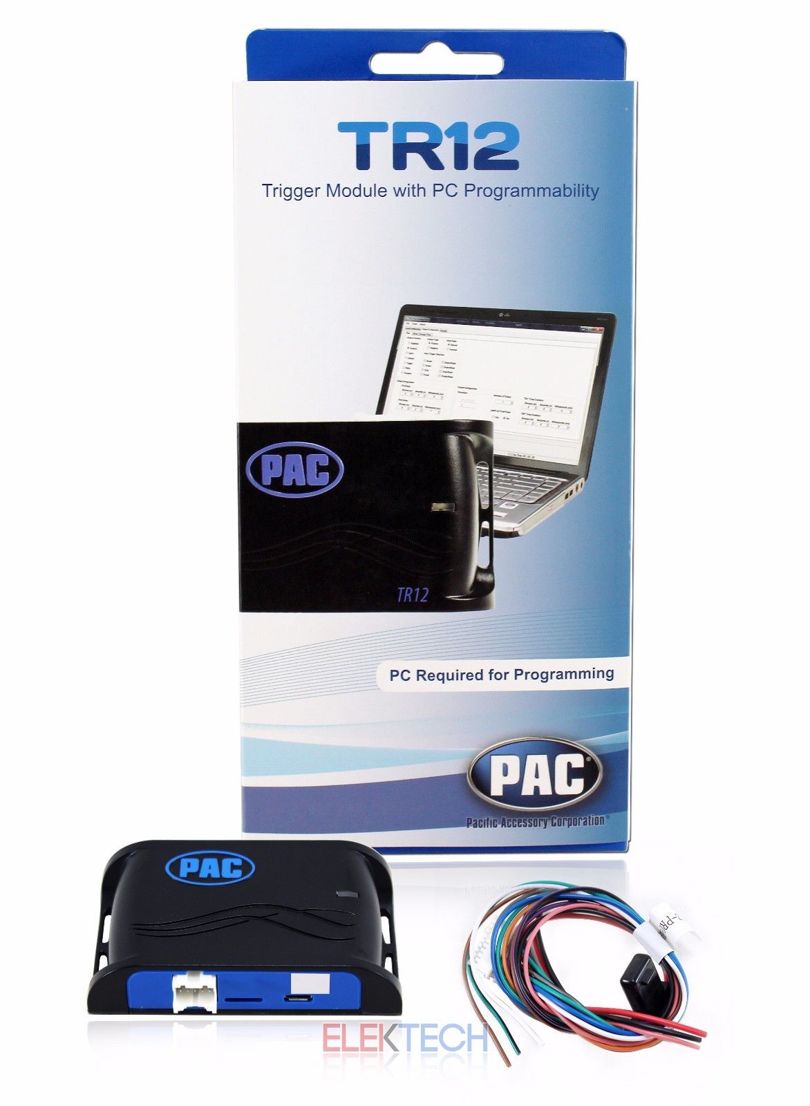
Easy as it's going to get...
That switch is designed for CAN BUS- will NOT work with a simple relay....
Here's how to do it for about $40-
I wired a newer BMW push start button , BMW headlight switch - and currently working on a M-B electric parking brake to control my E-Stopp parking brake.
The inputs can be set to trigger from a certain number of pulses (positive or negative), a selectable trigger voltage (from .20 volts to 14 volts in .20 volt
increments) or from a latched and pulsed input. The four outputs can be programmed for pulsed, latched or timed 12v or ground
and have a current rating of 3A each. So if you are running relays at the headlights- you'll be good to go.
OH- you have a laptop USB input to program ... It's really easy!!!
Install instructions-
https://www.carid.com/images/pac/ite...structions.pdf
https://www.ebay.com/itm/PAC-TR12-Vi...m4383.l4275.c1
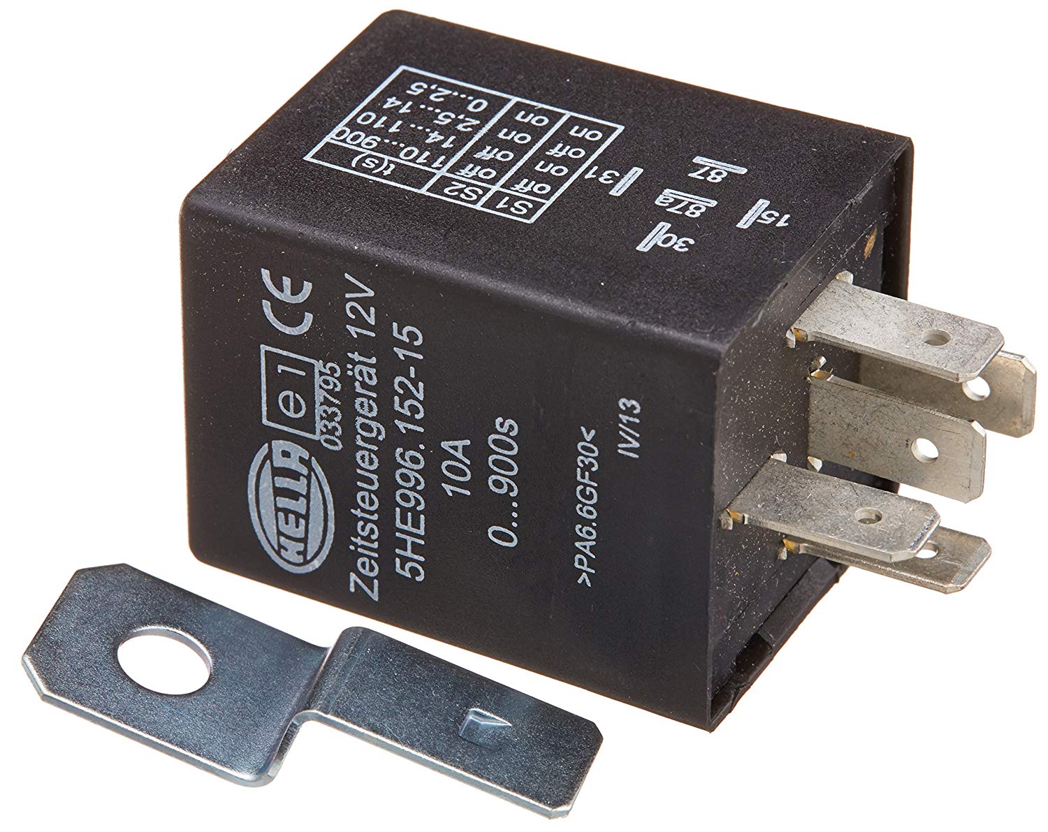
Oh- if you want your lights to shut off after you turn the car off- one of these Hella relays can do it- programmable from 0 to 900 seconds (15 minutes)
https://www.amazon.com/HELLA-9961521.../dp/B003C508Y8
Timer relay
Here's it's smaller brother - TR 7- I used it to control my door locks- push one unlocks- push 2 times with in 5 seconds it locks-
12-04-2017 #10 Registered User
- Join Date
- Jul 2013
- Location
- Gilbert, AZ
- Posts
- 934
^^^ Wow, that's pretty cool stuff! I'll have to keep that in mind, there's a lot of cool stuff that can be done with that.
Josh Campbell- Pushing the limits of my HOA since 2011
71 Firebird- 455, Ridetech front suspension. https://www.pro-touring.com/threads/...04#post1124504
67 Camaro RS/SS clone, Speedtech front suspension, coilovers, soon to get LT1/T56.
82 Z28- cheapie beater, soon to get a 406.
66 Mustang coupe- 393, T-5, sold. https://www.pro-touring.com/threads/...-Coupe-GT393-C
12-04-2017 #11
Registered User
- Join Date
- Oct 2011
- Posts
- 696
Sorry for the possible stupid question, but how would I make the TR12 work with my headlight switch and relay's? Can anyone give me like an example of how I can possibly wire this up and set up the controller? I also love the actuator feature because I also want to wire up an electronic parking brake. Thanks!

 Reply With Quote