

Results 1 to 20 of 132
-
06-13-2015 #1

 Starting The Transformation
- Join Date
- Feb 2010
- Location
- El Segundo, CA
- Posts
- 268

1956 F100 (Project Fat Max) Build Thread
After getting ready to build a new frame for my 56, I decided to scale back a bit and just build new control arms first. As an experiment. Once I got into the project I decided to upgrade the brakes as well.
The chassis I have now was built by someone else. I am not very happy with it. High on my list of dislikes was the front suspension. The biggest problem was that there is less than 4 degrees of caster, which makes the truck a little darty on the freeway. Basically impossible to drive with one hand in a relaxed manner. I also have Wilwood Pro Spindles which run 11 deg KPI. Anyone who's read Ron Sutton's suspension threads realizes the problem, a large loss of negative camber on the outside wheel when cornering. Not great for a truck that was built to corner. Also the steering is extremely light. I run a KFI power steering pump and had to back down to their most restrictive port on the pump outlet to get some semblance of steering feel. I run manual brakes so the juxtaposition of heavy brake pedal and light steering is disconcerting.
The guy who built the suspension must have realized the error with caster, as the rod ends on the upper control arms (which are meant for adjusting camber) had been tweaked as far as possible to move the upper balljoints back, to get more caster. As a consequence though, the jam nut on the rear rod end on each control arm was rubbing the mounting tab on the frame. Not good. Add to that the upper control arms were mounted upside down, or mixed up left to right, since the ball joint cup, which should angle upwards to match the KPI angle of the spindle, were instead angled down. This limits the range of motion of the balljoints.
The lower control arms use some type of poly-urethane bushings, which is horrible for friction. Also the front leg of each control arm was rubbing on the subframe. Add it all up and the front suspension had a ton of friction.
The answer is new control arms, designed to move the upper and lower ball joints to better positions, and with reduced friction via better design.
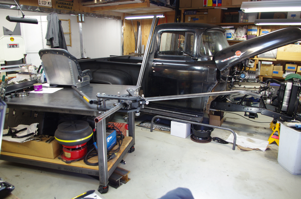
Step one in building control arms is building a fixture, use the old control arms as a template. That's how far I am at this point.
This pic shows the old control are mocked up in the fixture:
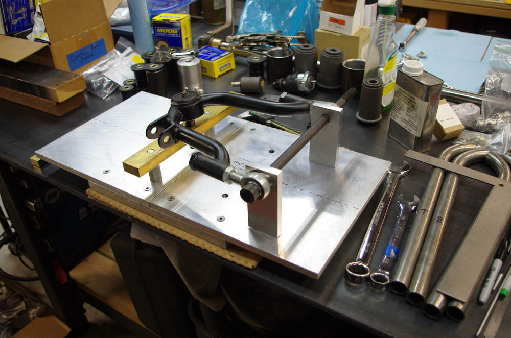
I built the fixture out of some machined aluminum plates that I used for mass loading audio equipment about 10 years ago. You need a good flat surface to start with.
Here is the fixture with the ball joint and cup positioned 1 inch further forward and 1/2 inch further out (to increase track). The rod ends are positioned so that they will fit the frame, and I have the threaded adapters screwed onto them. All that is left is to connect the dots with 1 inch OD DOM tubing and weld.
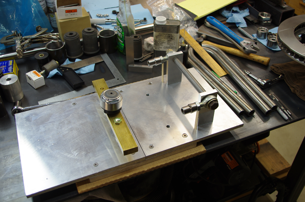
The same fixture is partially ready to do the lower control arms, you just flip it 180 degrees. Also the brass bar that has a tapered hole for the balljoint can be flipped to build the left and right control arms.
I'll keep updating the thread as I bumble along. I'm having to do a lot of work with the brakes most of which is my own fault (I prefer black anodized calipers over black power coat for the look I'm after).
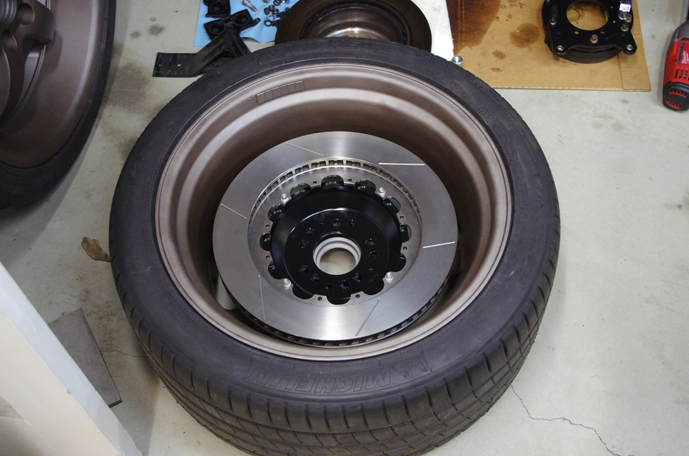
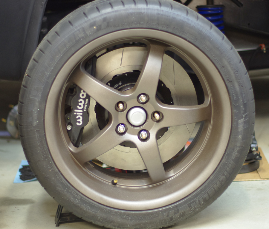
Here is a pic of the 15" rotor inside my 19" x 10" wheel. I've painted them dark bronze which looks much better.
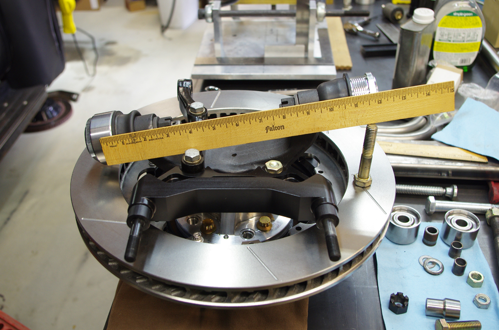
Here is also a picture showing how I measured the distance between the center of the upper and lower balljoints on the spindle, which you need to know to calculate how to change the caster. In this case the distance is 11.25 inches:
-
06-14-2015 #2
Registered User
- Join Date
- Feb 2011
- Location
- Indpls, IN
- Posts
- 613
What paint are you using on the wheels?
06-14-2015 #3
Starting The Transformation
- Join Date
- Feb 2010
- Location
- El Segundo, CA
- Posts
- 268
I think it's just Rustoleum or Krylon Dark Bronze. I bought it off Amazon. Originally Posted by Jetfixr320

06-14-2015 #4
Registered User
- Join Date
- Mar 2013
- Posts
- 36

definetly gonna watch this progress
being based in South Africa importing part etc is basically out off the question due to costs
will pm you a little later
06-15-2015 #5 Registered User
- Join Date
- Sep 2010
- Location
- corona,ca.
- Posts
- 1,081
You need tall ball joints or tall spindles to change the height of where the ball joint center lines are now ive from what i have been told.
How many degrees are you going to get moving the uca bj forward?i maybe wrong,but i thought you need to move the uca bj cl back,lca forward to get more positive caster,and shorten the uca,or lengthen the lower,which you probably have done to get more neg camber?not sure what you have in your picture.hit ron sutton up hes the master on this stuff.72 chevelle.
06-15-2015 #6
Registered User
- Join Date
- Sep 2010
- Location
- corona,ca.
- Posts
- 1,081
Btw,im really digging you making your own parts,in a hobby now known for just picking up the phone or clicking a mouse to get a better performace part,its really cool to see this!
I too try to make as much of my own stuff as possible.machinist by trade,welder.painted my car etc. We need more giys like you.
Phil72 chevelle.
06-15-2015 #7 Registered User
- Join Date
- Dec 2006
- Location
- Out of the Burbs of Detroit to SoCal, then onto my ancestral homeland, the woods of Cascadia
- Posts
- 1,753
So are you deciding to live with the 11 degree KPIA? I was thinking of using the Wilwood spindle in my European Capri (Currently Mac Strut), didn't like the KPIA, but short of fabbing a one off spindle or going with a Coleman custom (still on the table for me), i'm kind of at a loss.
I need to sit doen and layout the wheel/tire/hub-brake vs KPIA to figure out what scrub radius will be, that's what will drive my KPIA
Editted for spelling, mostlyGreg Fast
(yes, the last name is spelled correctly)
1970 Camaro RS Clone
1984 el Camino
1973 MGB vintage E/Prod race car
(Soon to be an SCCA H/Prod limited prep)
06-15-2015 #8
Starting The Transformation
- Join Date
- Feb 2010
- Location
- El Segundo, CA
- Posts
- 268
Hey Tiger. Good catch on the forward direction of the upper ball joints! Yes, that is the wrong direction in terms of adding caster. But...I will move the lower ball joints forward 2.4 inches. So 1.00" for the upper balljoints and 2.40" for the lower ball joints. This will move both ball joints (and the front wheels) forward 1" (which I want) and then, since the spindle is roughly centered half way vertically between the lower and upper ball joints, another 1.4/2 = 0.7 inches forward for the front wheels. So a total forward movement of the wheels of 1.7 inches, which is planned. Originally Posted by chevelletiger
The current caster is less than 4 deg and I want 11 deg to match the KPI for camber considerations when turning. The distance between the ball joints is 11.25". To get an additional 7 deg of caster the lower balljoint has to move forward 11.25*tan(7°) = 1.38". Hence the 1.4 inches mentioned above.
Now I realize that 11° is a ton of caster. That's what I consider this an experiment. I will have to change out the restricter on the power steering pump to change the assist level. I'll play around with it and see how it feels. Then decided whether to us a new spindle with less KPI when I go to build my new frame (with new suspension all around). The assumption being that less KPI will allow less caster and still maintain good camber when turning.
Since the wheels I am running now are 19" x 10" with ET45 (45mm of offset), the 11° KPI helps keep the scrub radius reasonable. Adding 1.5° static negative camber yields 1.36" of scrub radius. Not great but not horrible. Hope all this makes sense...
06-15-2015 #9
Starting The Transformation
- Join Date
- Feb 2010
- Location
- El Segundo, CA
- Posts
- 268
For now I do plan to keep the Wilwood Pro Spindles. Mostly because that's what I have already. But also because it helps with scrub radius in light of the offset of my current wheels. If I get new spindles down the road I'd be eyeing the Ron Sutton versions. But that would require new wheels with more offset to keep scrub radius reasonable. I've thought about making my own spindles, the tough part is getting pins, bearings and hubs. The ideal would be a bolt-on pin, that way you can machine the spindles out of aluminum and do whatever you want. I've not yet found the right pin though. Offroad guys make nice ones, but I'm not sure they'd work with my style of wheel. If anyone has any info, I'm all ears. Originally Posted by Twentyover
06-15-2015 #10
Starting The Transformation
- Join Date
- Feb 2010
- Location
- El Segundo, CA
- Posts
- 268
Just finished up the first leg of one upper control arm. I actually started on this a couple of years ago, so the tubes were part way bent, but not enough. It's always a bit finicky to stick a bent tube in the tube bender, so there are two bends separated by a short distance. Perfectly workable but if I did it over I'd should be able to achieve the same goal with a single bend.
The bender is from JD-Squared and works great, though I always have to read the directions to figure out how it works! Once you get it sorted it is real easy.
06-16-2015 #11
Starting The Transformation
- Join Date
- Feb 2010
- Location
- El Segundo, CA
- Posts
- 268
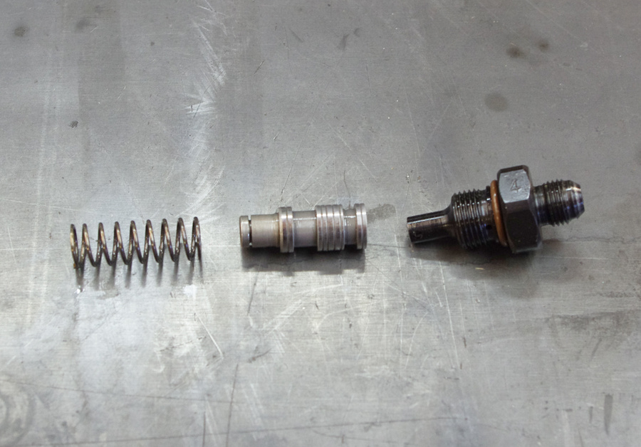
First control arm done, three to go. Just waiting on the ball joint cups. I assumed the bottom ball joints for the Wilwood Pro Spindle would be the Chrysler large 727 size, but those did not fit. So I am using the smaller 772 size top and bottom. Using QA1 low friction ball joints.
06-16-2015 #12
Starting The Transformation
- Join Date
- Feb 2010
- Location
- El Segundo, CA
- Posts
- 268
So as I mentioned earlier, at the same time that I am redoing the front suspension, I am also redoing the brakes.
Up until now I've been running Wilwood Superlight calipers up front, 6-piston, with 14" x 1.1" rotors. The rear brakes are Dynalite calipers with 12.19" x 0.81" rotors. I have dual Tilton master cylinders and a Wilwood pedal assembly with balance bar. This is a manual setup, which I love for the feel you get when braking.
The problem with manual brakes, on the street at least, is brake effort. In an effort to improve this, I lengthened the brake pedal arm about an inch, added some Hawk Blue pads up front, and played around with master cylinder sizes until I got an acceptable balance between brake effort and pedal travel. But I knew it could be better.
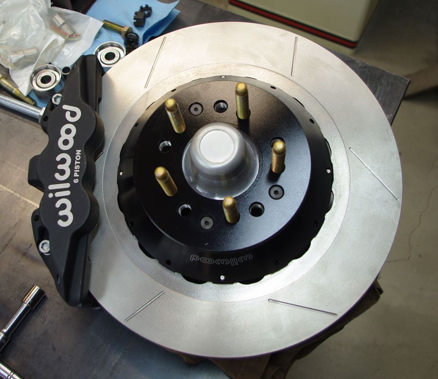
Then, while perusing around the internet, I noticed that Wilwood came out with a new caliper design, the Aero6. The Aero4 appears to be the same caliper body, with the center pistons omitted. I further noticed that the Aero6 would work with 15" rotors. Hmm, that got me thinking. The beauty of bigger rotor diameter is that you get more brake torque with no change to pedal travel. The downside is extra weight, unsprung and rotational. Of course the extra mass is beneficial at the track in terms of absorbing heat, but otherwise it is no helpful. I rationalized that the 5-6 lbs saved with my new wheel and tire combo (per corner) would even out the extra 4-5 lbs of rotor mass. I was sold.
Now the extra brake torque will translate directly to less pedal effort. Or if I increase the front master cylinder size I can get the same brake effort as I have now but with a stiffer pedal. Both are attractive options. Anyone who states (and many do) that all you need from your brakes is to be able to lock up the tires, the rest is unneeded, is missing the point. The point of good braking is to be able to decelerate as rapidly as possible without locking the tires. And to do that repeatedly requires good modulation. A stiff brake pedal translates directly to improved modulation. This has been borne out by decades of F1, Rally, and Endurance racing. Top end drivers want a rock hard pedal, with zero system flex. That is the goal. And to combine that with acceptable pedal effort.
Ok, having established why I wanted 15" rotors, the next trick was to make it work with my Wilwood Pro spindles. Wilwood does not make a kit for this spindle with 15" rotors, only for 14" rotors. So I did a little R&D (rip-off and duplicate). The brake kit I had on the truck is made for two rotor diameters, 13" or 14". To accommodate the 14" rotors, Wilwood simply adds spacers on the caliper bracket to move the caliper out further. So I figured I would try to do the same in going from 14" to 15" rotors with the new caliper bracket that comes with the Aero6 kit. And after playing with some spacer sizing, this worked out perfectly.
Here's a few pictures of the mockup stage:
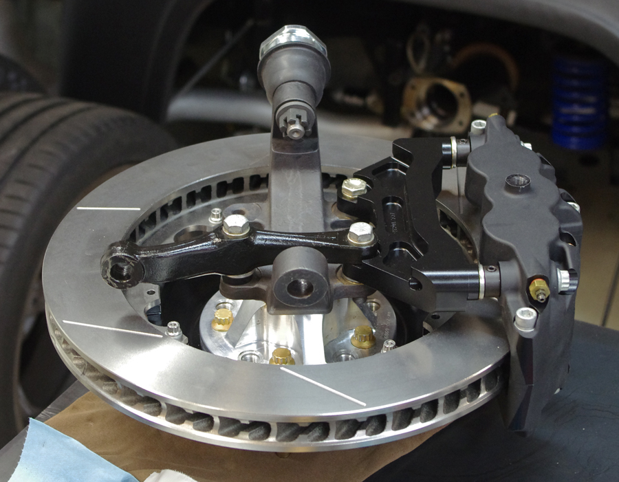
Even though my wheels are 19", the calipers are a snug fit. That's because the wheels are cast, and therefore pretty thick where the barrel meets the spokes. But it fits.
06-26-2015 #13
Starting The Transformation
- Join Date
- Feb 2010
- Location
- El Segundo, CA
- Posts
- 268
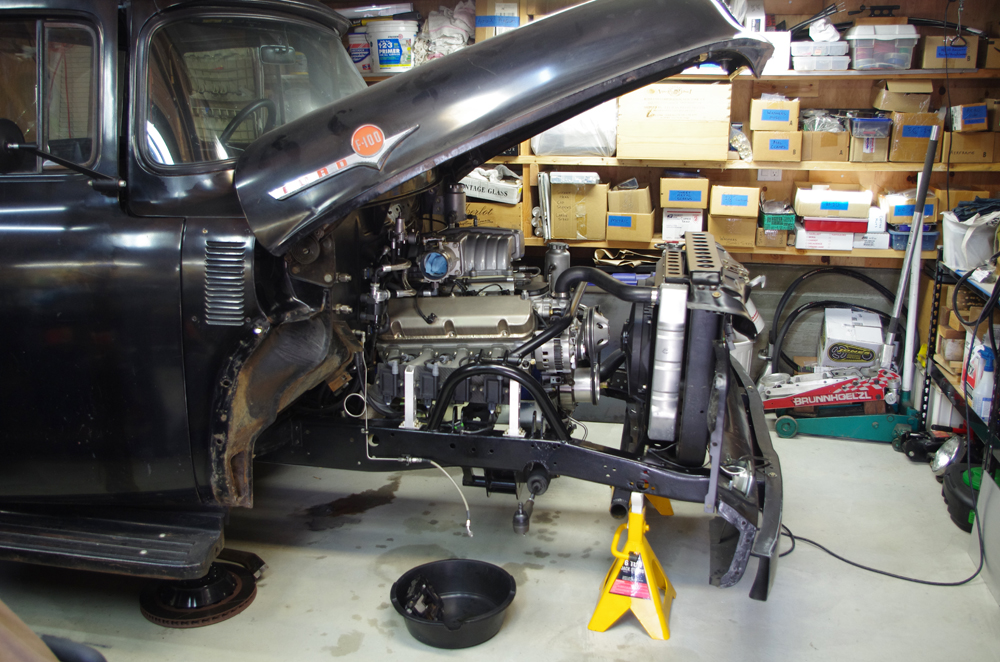
A few updates on my project. I removed the front fenders and liners so that I could get better access to the suspension:
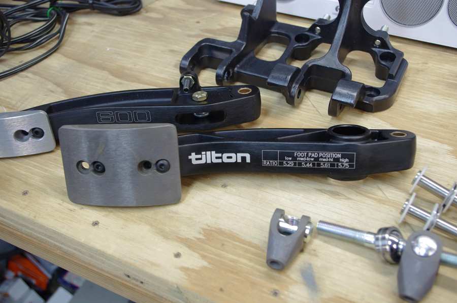
I also purchased a Tilton pedal assembly as part of my brake system overhaul. It's a real nice piece, very well made:
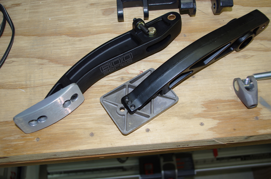
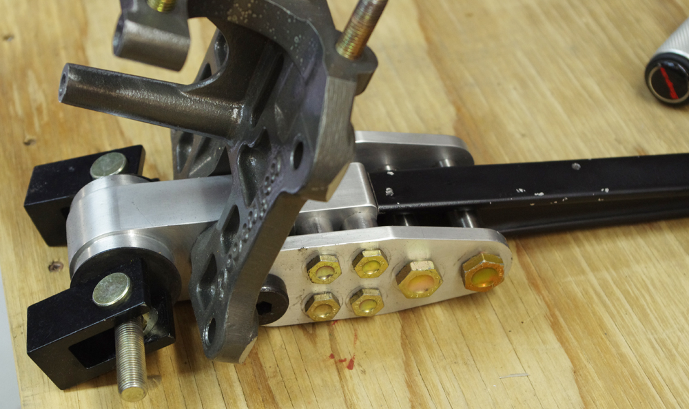
Since I do not need the clutch pedal, I cut the pedal cluster in two:
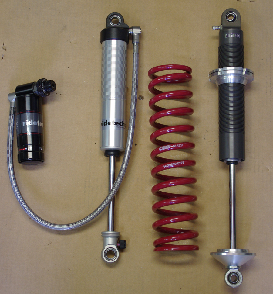
I also got some new front shocks as part of the suspension rebuild. The rear shocks are Bilsteins valved to work with the truck arms. When I build the new frame I plan to go to 3-link and at that point I'll get matching Ride Tech shocks for the rear. For now it will be a hybrid.
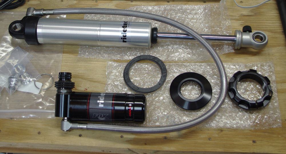
Here are the new front Ride Tech shocks compared with my existing Bilstein ASN's. The ASN's are the 7" stroke version, the Ride Tech's are 6" stroke. Since the shock picks up the control arm way out by the ball joint you need more travel. I am not sure if the 14" springs will be too long, we'll see.
More to come...
07-02-2015 #14
Starting The Transformation
- Join Date
- Feb 2010
- Location
- El Segundo, CA
- Posts
- 268
Just a few small updates.
The following photo shows my new Tilton brake pedal compared to my old one. The old one is a Wilwood underhung. I put it upside down for the picture and lined up the two pivot points to illustrate the difference in pedal length (leverage).
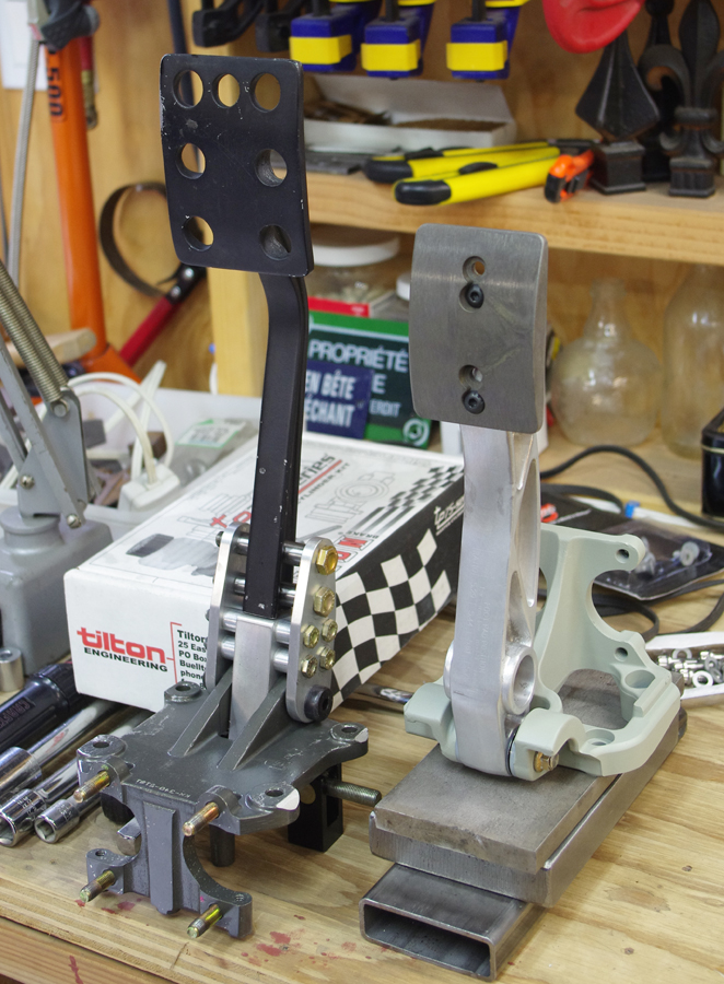
The plan is that the reduced leverage from the pedal will be compensate for by the increase in stopping power from the larger front and rear brake disc diameters. For sure the new pedal will be stiffer than the old one.
This next photo bears out the saying that "necessity is the mother of invention". When the original brake system was first installed the pedal effort seemed high to me. So I played around with lengthening the brake pedal as well as master cylinder bores to get it where it felt ok. Also, the brake pedal pad was physically too high off the floor. It was easier to lengthen the pedal arm than to try to remount the pedal cluster further down (though I did try to do that). I'm glad that the pedal cluster and master cylinders will not longer be up under the dash with this new configuration as it was a real bitch to work on with all the wiring and stuff in the way.
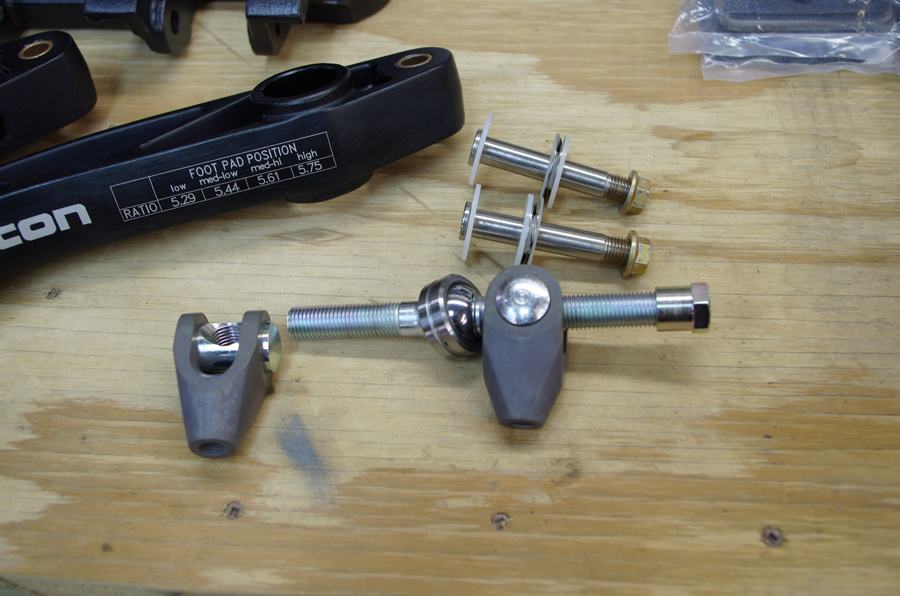
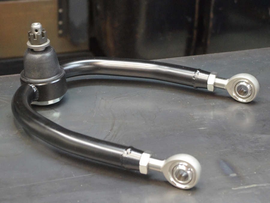
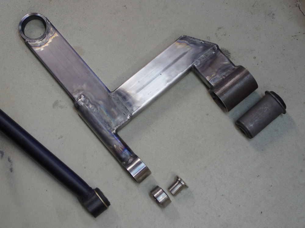
Here just a quick picture of one of my upper control arms all finished up with nice new NHBB rod ends. I'll be starting the lower control arms soon. Just waiting on some bushing sleeves from a local machine shop.
07-02-2015 #15
Starting The Transformation
- Join Date
- Feb 2010
- Location
- El Segundo, CA
- Posts
- 268
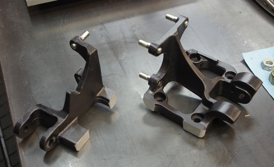
Forgot to add a couple of pics of the new Wilwood Aero6 calipers vs the old Superlight calipers.
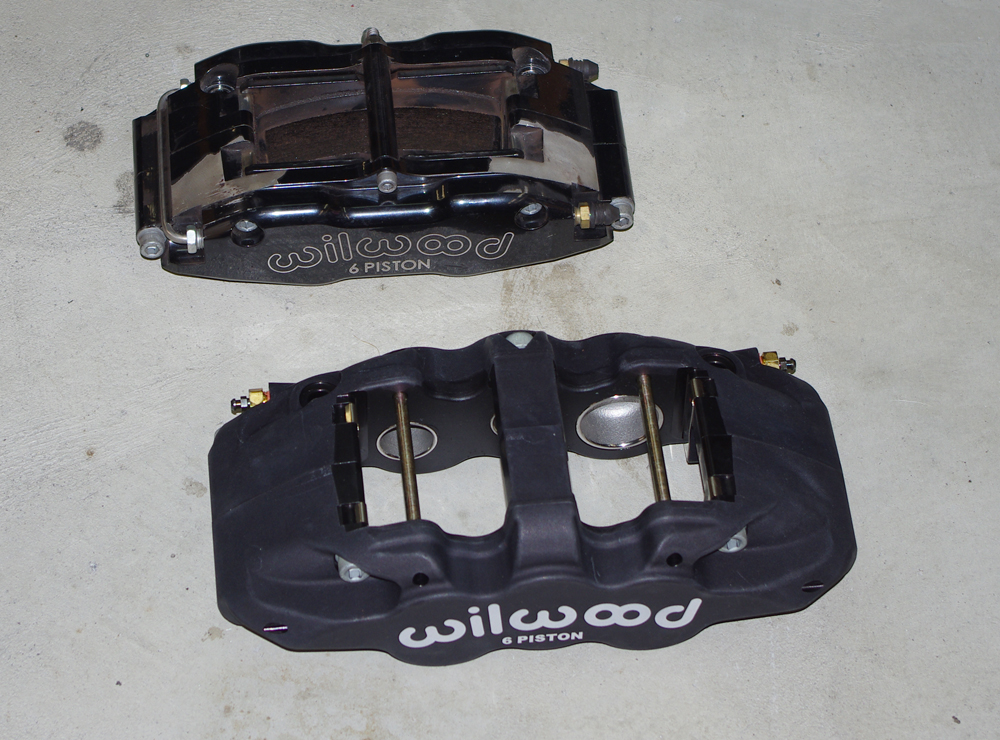
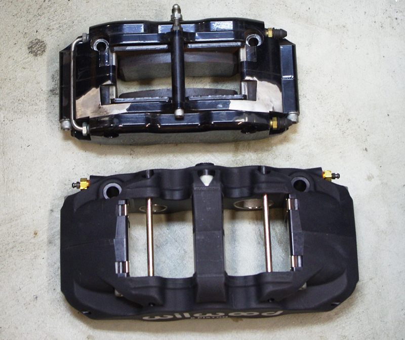
The mounting studs are further apart and larger in diameter. And the whole caliper is a lot bigger. Looks like it should be stiffer as well eliminating system flex.
I've always been a big fan of mono block calipers. It just makes sense to me that they would have a better stiffness to weight ratio. Some Brembo GTR's would be have been nice.
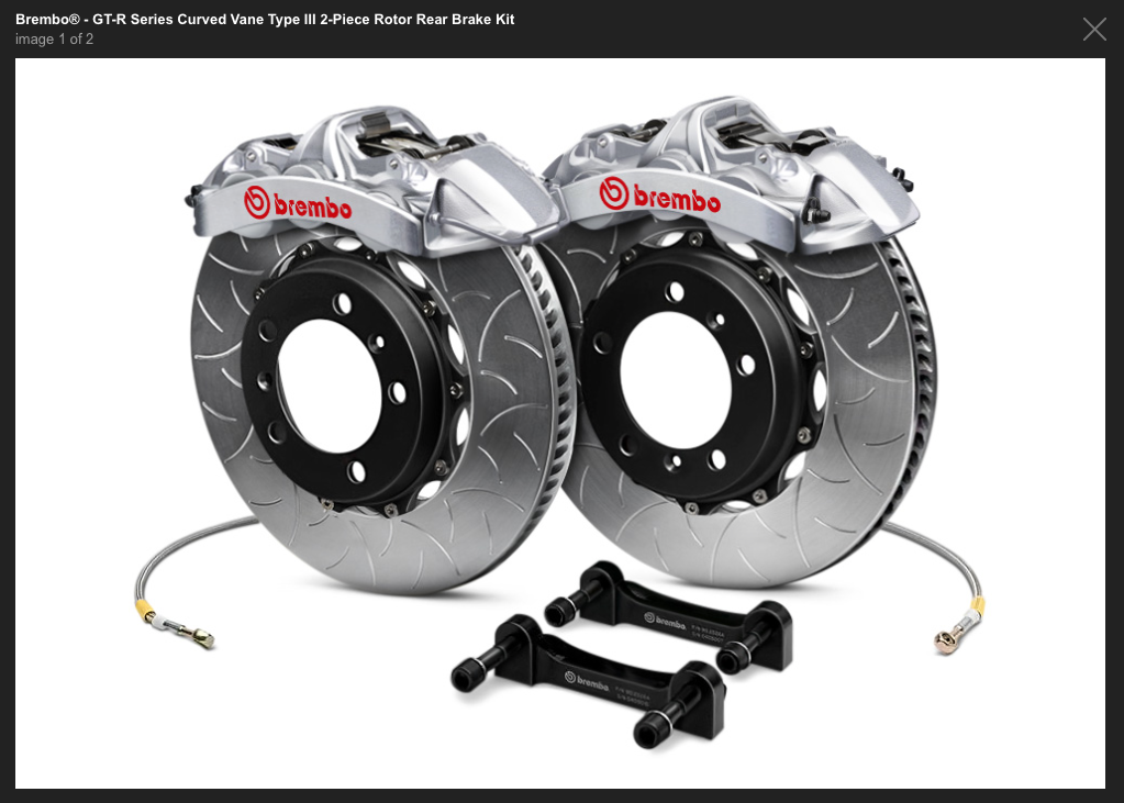
But there is simply not enough info on them online, they are expensive and a bit overkill for what I'm doing here.
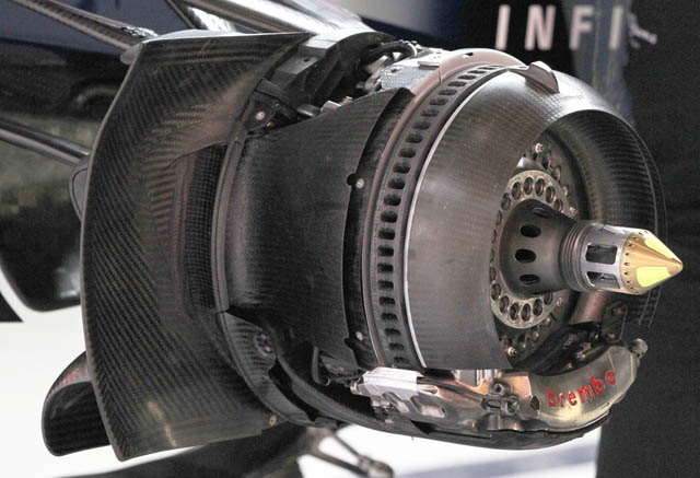
If you keep pursuing better brakes you end up with this!
07-12-2015 #16
Starting The Transformation
- Join Date
- Feb 2010
- Location
- El Segundo, CA
- Posts
- 268
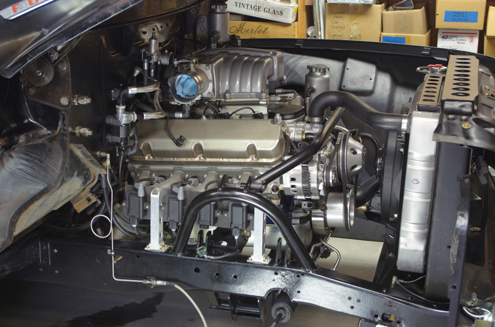
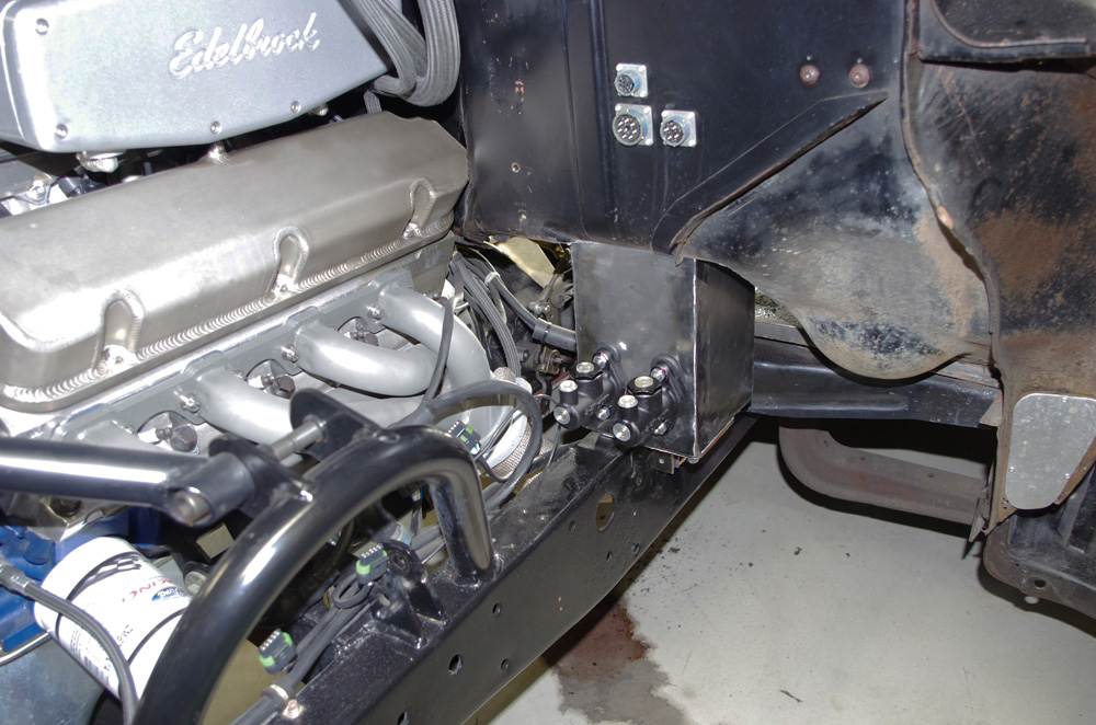
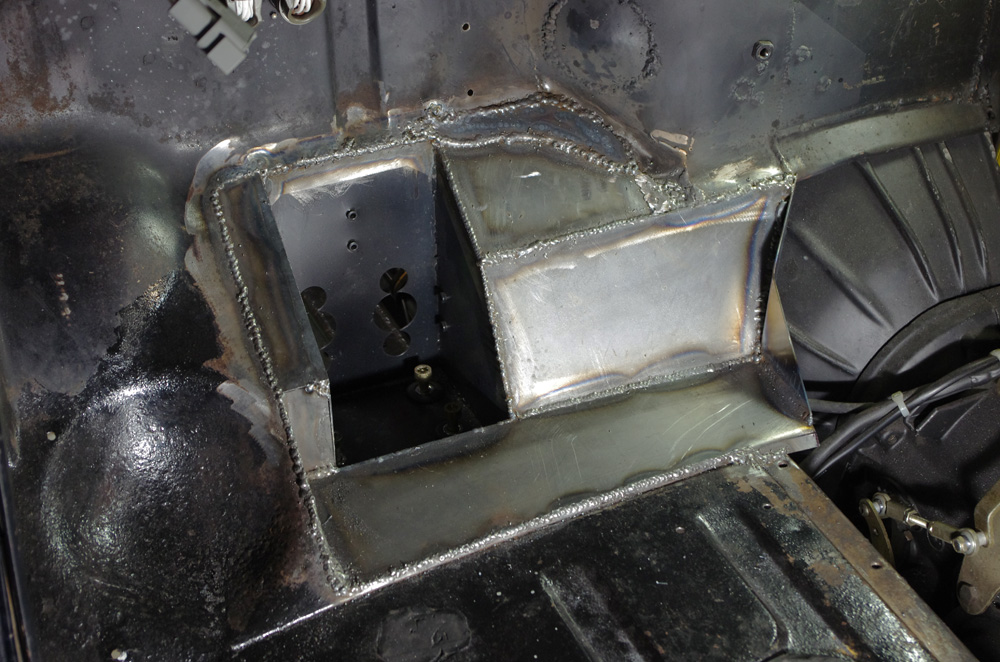
Latest updates. Seems like I'm spending all my time taking things apart. But things are coming together on various fronts. Often stuck waiting for a part or materials so I can move on, so I jump around on the various projects. Here I cut the floorboard to make room for the Tilton brake pedal. I decided to mount it to the frame, and then extend the sheet metal around it, so it is still "inside" the cab. The master cylinders will now be in the engine compartment though, with the fluid reservoir mounted to the firewall above.
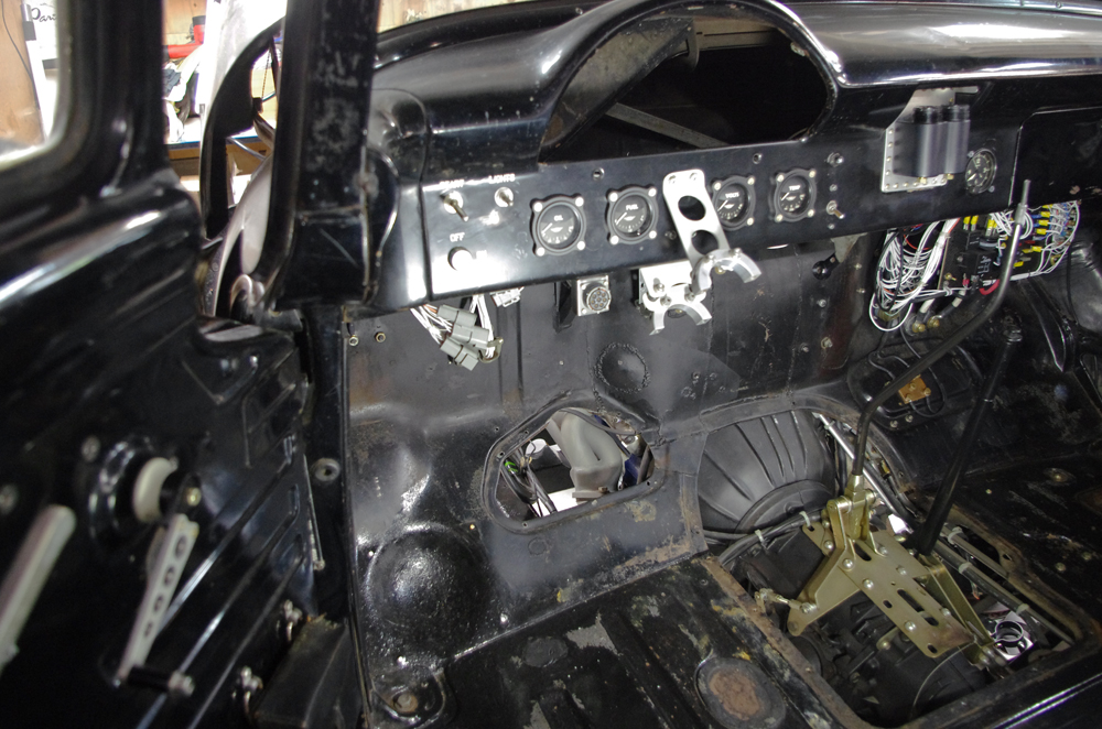
Now, with part of the floorboard cut out:
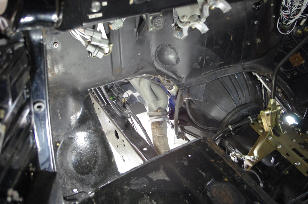
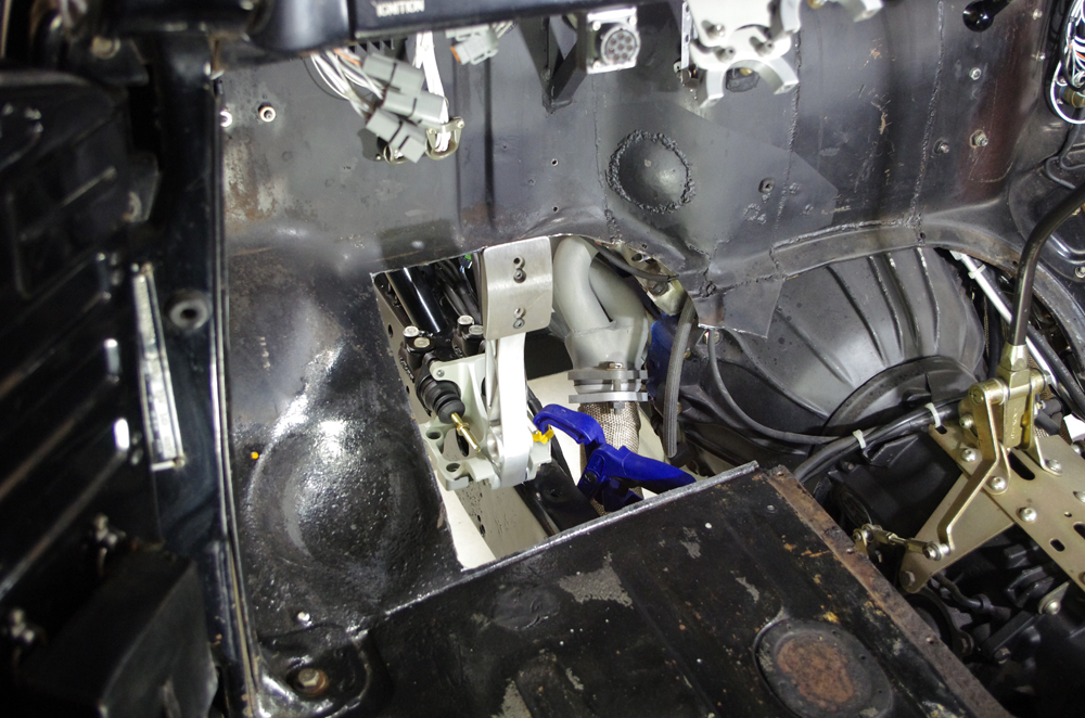
I clamped the brake pedal to the frame as a mockup:
You can see where I welded in a dimple for the valve cover. I found out I had to do that kind of late, and so tried to weld in the dimple with a bunch of stuff in the way. Did not clean the metal properly and just had a miserable time doing it, as the quality of the welding bears out. One day soon when I take the cab off, I can really get at it and clean it up.
Here you can see the where the pedal cluster will bolt to the frame:
Since the cab is still soft-mounted, I'm going to have to get tricky with how the sheet metal envelops the pedal cluster. If I make it all solid it might crack the sheet metal, I don't know. Better to be safe so I will use rubber grommets to let the sheet metal 'float' around the cluster.
One of the other things I'm doing on this go-around is building a new mounting platform for my seats. Here's a pic where I'm bending the 1.5" x 0.095" DOM tubing that will comprise the platform. More to come on this.
Lastly a pic of my KRC power steering pump flow control valve. Since the truck was built with so little caster (4 deg) I found I had to go to the most restrictive valve (least amount of boost) in order to get some semblance of steering feel. Now I'll have 11 deg caster, so will have to change out the valve to a less restrictive one. There are I believe 9 valves available to choose from. Pretty handy.
Gustave
07-18-2015 #17
Starting The Transformation
- Join Date
- Feb 2010
- Location
- El Segundo, CA
- Posts
- 268
A few more updates.
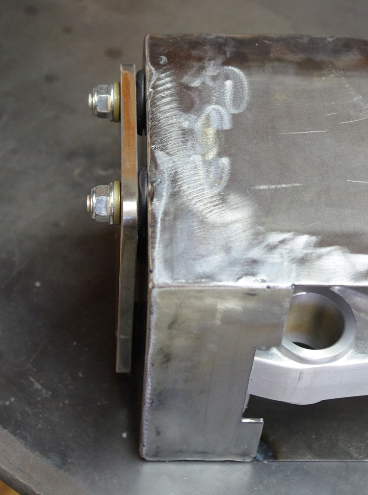
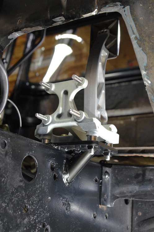
I built a sheet metal enclosure for my brake pedal assembly. I refer to it as a "pedal box". This is so that, even though the pedal cluster will be bolted to the frame, it will still be located "inside" the cab, along with the balance bar. The master cylinders will mount just on the other side of this box, inside the engine compartment.
Here you can see the completed box, along with the grommets and steel spacers what will solidly mount the pedal cluster and master cylinders to the frame, while allowing the sheet metal box (which is part of the cab) to float around it.
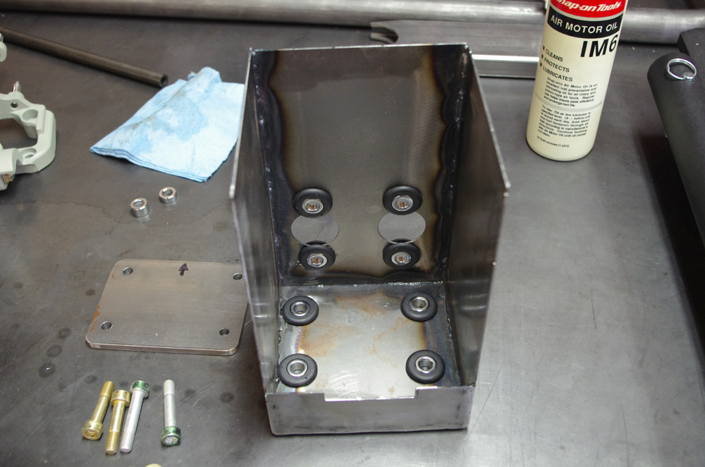
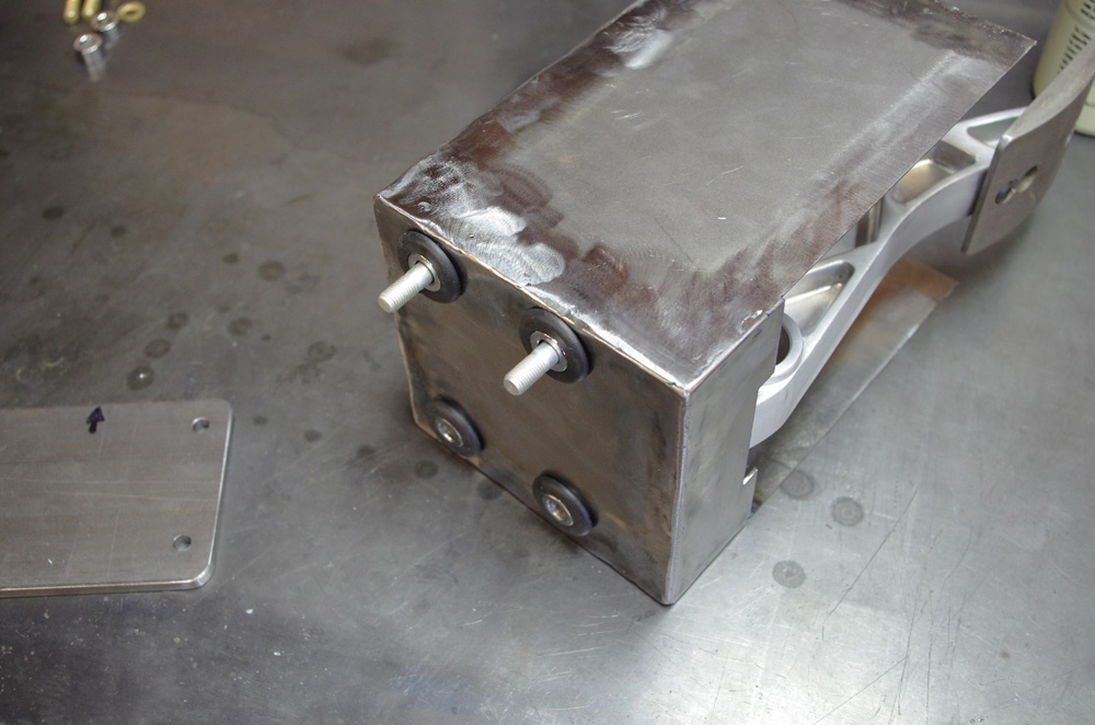
The metal plate shown on the left will be welded to the frame, and is what the pedal cluster will bolt to:
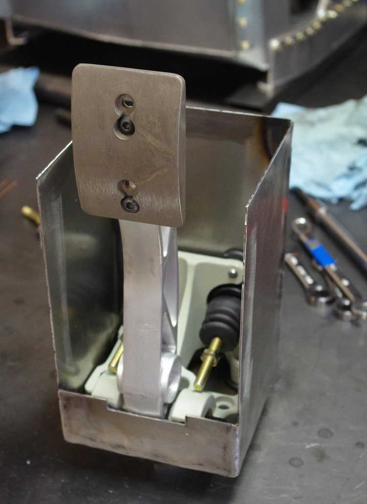
The completed box mocked up with pedal cluster and master cylinders:
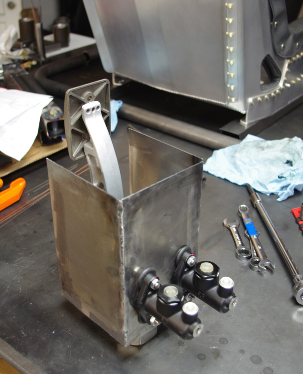
And here is the pedal box mounted to the frame showing where it will be relative to the cab floor:
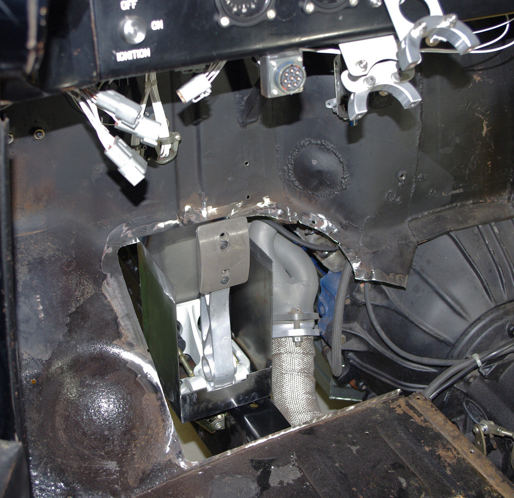
I have to fill in the area around the pedal box to rebuild the cab floor. The idea is to keep the flat portion of the cab floor going forward for another 4-5 inches to give more legroom. This is important because I am moving the seats down, and as you do that, your legs get scrunched up unless you provide more room forward for you feet. I'll be building a new throttle pedal, also hinged from the bottom, and mount it over on the right. The main interference is from the valve cover, which is located pretty much where my toes will want to be at full throttle. It will be a tight squeeze getting it all situated, but that's the fun of it.
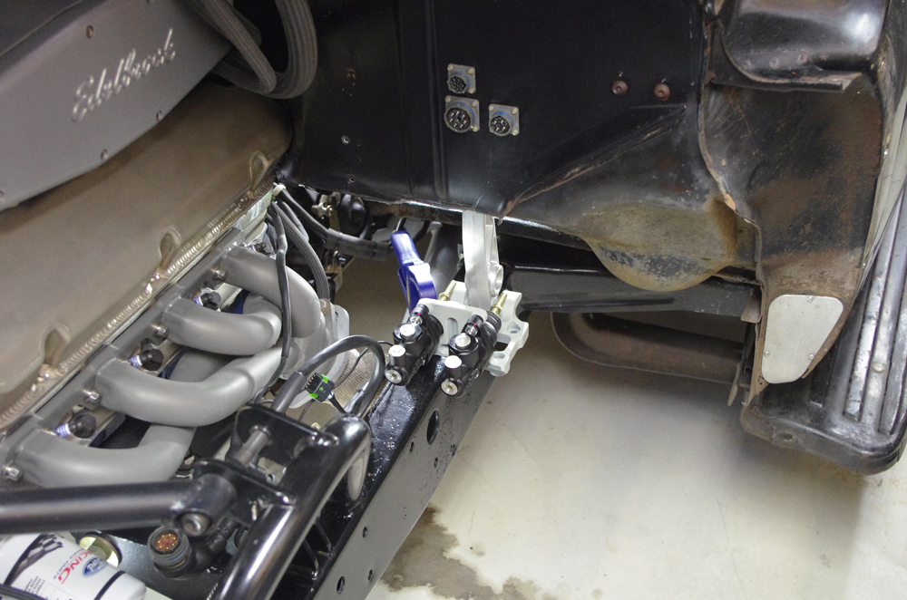
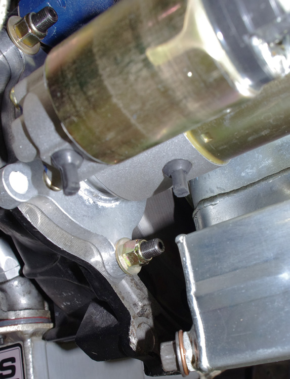
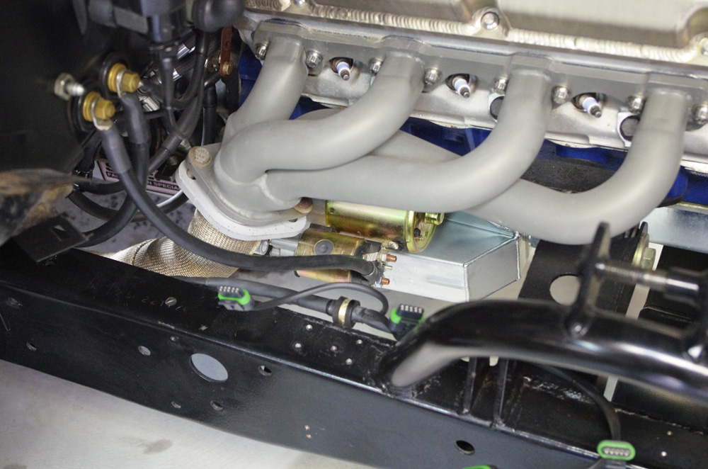
I also installed a new RobbMc starter motor. With my previous starter the solenoid was stuck right up under the headers and the available adjustments could not get it out of that region. The RobbMc unit has the motor axis concentric with the pinion axis, allowing a lot more possibilities in positioning the solenoid. It really is infinitely adjustable and I was able to put the solenoid well down away from the heat of the headers. I also changed over from bolts to studs to mount the starter. These are dual thread pitch studs, 3/8-16 to go into the bell housing and 3/8-24 for the nuts that hold the starter down. Also the portion of the studs where the starter sits are unthreaded, so I won't have the aluminum starter mounting flange being ground away by steel coarse thread bolts. Just good practice.
Gustave
07-18-2015 #18
Registered User
- Join Date
- Sep 2010
- Location
- corona,ca.
- Posts
- 1,081
Dr.G,question.
How do you keep your work bench from moving while using your bender?
It looks like you have casters on there.
Keep up the good work,im loving the fab!
Phil72 chevelle.
07-18-2015 #19
Starting The Transformation
- Join Date
- Feb 2010
- Location
- El Segundo, CA
- Posts
- 268
Good question. I used what they call "self-leveling casters". For mine you have to turn a little dial on the caster and it lowers a big rubber foot down onto the floor, taking weight off of the caster. That keeps the work bench from moving around. I have to have the thing on wheels since my garage is not big and I have to move stuff around depending on the project at hand. Gustave Originally Posted by chevelletiger
07-26-2015 #20
Starting The Transformation
- Join Date
- Feb 2010
- Location
- El Segundo, CA
- Posts
- 268
I finished modifying the cab floor to accommodate the new brake pedal and provide a bit more forward leg room:
I will have to modify the tranny cover to match this new floor. And I will build a bottom hinged throttle pedal to go on the right once I get the seats back in so I can test fit everything. The C-shaped patch along the top of the new metal was a repair. I had a perfect fit for a butt joint along the top, but a previous builder had sanded the old sheet metal so thin (during a firewall reshape) that when I went to tack in the new metal, the old metal just vaporized. So I was left with a 1/4" gap to contend with. After trying to fill it with MIG I finally realized it better to just put a patch over it. When I get the cab off during my new frame construction (first half of next year hopefully) then I can get proper access to try and fix this area properly. Right now with the engine in the way it is just too difficult.
Here is the completed pedestal I built to mount the brake pedal cluster to the frame:
This should be plenty stiff and the new floor will wrap around the brake pedal, with the master cylinders outside in the engine bay. That part turned out just how I'd hoped.
Here is the start of the new seat mounting base I made:
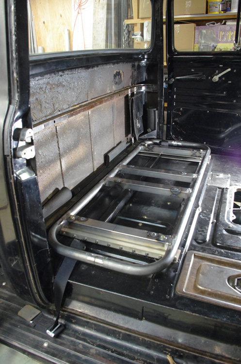
I showed pics of me bending this tubing earlier. It's 1.5" 0.095 round with 0.065 rectangular. I have a habit of overbuilding stuff. If I did this again I'd make the whole thing out of 0.065
The seat platform bolts to aluminum adapter brackets, which pick up the original 8 threaded holes in the cab floor. The seat sliders will bolt to this platform. I welded little cylindrical tubes through the rectangular sections so that they would not crush when tightening the bolts for mounting to the cab and the seats.
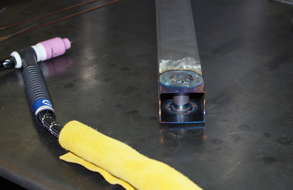
As you can tell I am still a total beginner TIG welder. But when I finish a weld, I look at it and ask myself it I will bet my life on it. If the answer is yes, then I move on. It's more the aesthetics and consistency of the welds I have trouble with. But I could sit there and weld practice coupons all day and not get the kind of practice I'm getting on all the various welding involved with these projects. So much variety. Different thicknesses, round to square, round to round etc...
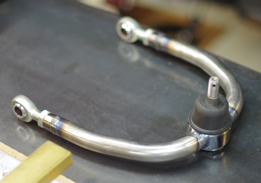
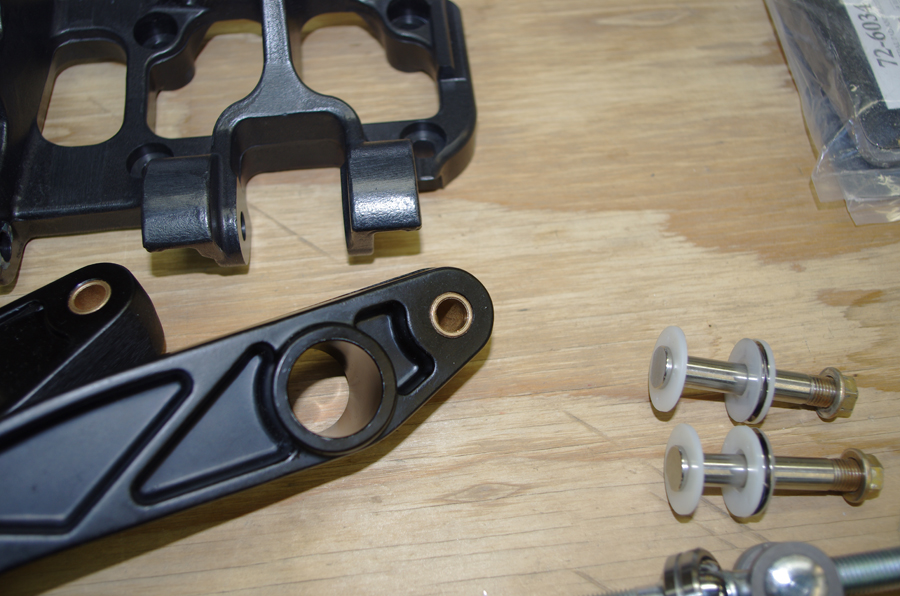
I've also mostly finished the first lower control arm. Here is a pic of it compared to the old control arm, which was made by a previous builder.
Surprisingly the new control arm weighs 6 lbs and the old one weighs 7 lbs. Though the new one still needs tabs for mounting the shock and sway bar.
The principle with this control arm design is to have a very direct path from the outer ball joint to the inner pivot point. To take up cornering loads with minimal deflection. Then the rear pivot point will be a rubber bushing. This allows the front wheels to move backwards a tad when hitting bumps, which is important for ride quality. I basically copied the principle from BMW, who used the same concept on the E30, E36 and E46 chassis 3-series cars. The only caveat is that the BMW's used McPherson struts, so as the lower out balljoint moved back, there was only a small change in caster, as in under braking. For my implementation there will be more caster wind-off during braking. We'll see how it goes, it is king of an experiment, and having to adapt it to my existing frame entailed certain compromises.
The front pivot is a regular spherical bearing to help deal with camber change when cornering.
Gustave

 Reply With Quote


