Results 121 to 132 of 132
-
05-06-2017 #121

 Starting The Transformation
- Join Date
- Feb 2010
- Location
- El Segundo, CA
- Posts
- 268
 Thanks for the encouragement Rob. Though it's only theoretical progress until I actually build something 8^)
 Originally Posted by RobNoLimit

I just glanced at a previous thread you started on your Sniper subframe. I had not seen those spindles before. Very cool. I cannot determine exactly what spindle you are using though. You call it a "short snout" spindle. Is that "short" in comparison to a Wide-5 snout? It looks like a 5x5 snout with the 2" ID bearings. I sort of consider this long in comparison to the 2.5" Grand National snout. Only because I am in the process of comparing and contrasting those two snout/bearing packages against each other. Although I don't have the parts to measure yet it looks like the 2.0" ID 5x5 snout has a larger bearing spread than the 2.5" GN stuff. That would be advantageous in some ways, reducing the loads on the bearings due to the torque caused by cornering forces. Though the larger 2.5" bearings might better handle the lateral loads from cornering. Still weighing this. Originally Posted by RobNoLimit
Of course the Wide-5 setup has a very wide bearing spread. And I know you used this on Hellboy. My concern with Wide-5, other than getting the right wheels, is what appears to be a very large WMS to Steering Axis distance. Then there is the Mini Wide-5 also. This was all incredibly confusing to someone like me, wading into the subject with zero prior knowledge. The most frustrating part is the inconsistent terminology used by the various places that make and sell these parts. 5x5 seems to imply generally the snout with the 2" ID bearings (I've also seen it referred to as 2" GN), though one can get 5x5 hubs with a 5x4.75 wheel stud spacing! And the GN stuff seems to be generally the 2.5" bearing concept, though some folks also refer to it as 5x5. Phew...
I may eventually punt on building my own spindles. Heck, I could just buy the Track Star spindles that Ron Sutton makes. But for me it is the journey as much as the destination. One thing that I feel a spindle should allow one to do is to change camber without affecting SAI. I wonder how many folks realize that the standard way of adjusting camber, by shortening/lengthening the upper control arms, or moving their pivots inwards or outwards, also affects the SAI by the same amount (deg. for deg.). I feel the upper ball joint should be bolted to the spindle, and that shims should be used to change camber. That's how they do it in F1 for example. I note your Sniper spindles have bolt-on upper balljoint mounts, though I do not know if they are adjustable. There are circle track spindles which use offset slugs to adjust SAI, though that would only happen if the upper control arm length was changed correspondingly, otherwise they are actually adjusting camber.
I am currently running 11 deg SAI with 11 deg caster and about 1.5" offset (scrub radius) and -1.5 deg camber. It feels generally ok except for on some of the high speed freeway transitions (like the 105 East to the 405 North which I sometimes take at about 100 mph) there will be some weird oscillations sometimes near the end of the corner as I slow down to merge. The first time it happened it kind of freaked me out, but I've learned nothing catastrophic comes from it. Make Ortiz, in one of his articles on this subject, mentioned also that some folks report weird oscillatory behavior with high SAI/Caster setups. Originally Posted by RobNoLimit
What really sort of turned me towards a low SAI low scrub configuration was reading Eric Zapletal's definitive write-up on front end geometry. It is very long, and examines each parameter of the front suspension (camber, caster, SAI, offset, trail) in detail, both individually and in combinations. The write-up is probably too long to post here, and would bore most readers to tears (as this is probably already doing). But here is Zapletal's conclusion:
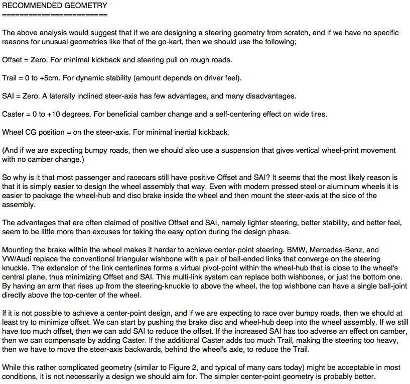
================================================== ===================
You bring up good points Rob, in that what is good for a low CG car might not necessarily be best for a truck. Also I am striving to set my truck up for dual purposes. Reasonable street comfort with reasonable handling for auto-x and lapping days. So I'll have springs and bars on the soft end of the spectrum (relative to all out performance builds), and hence more roll. For a while I thought that the jacking effect on the inside wheel produced by large'ish SAI (in combination with large caster and offset) would be an advantage worth pursuing. But lately I've not been so sure about that. And that is really the only advantage one could attribute to large SAI. And does it outweigh the loss of camber on the outside wheel?
Also regarding steering feel produced by offset (scrub radius). Is this really the "feel" we search for? The feel that tells you the tires are on the edge of adhesion and about to break away? Usually that type of steering feel is attributed to trail (induced via caster). Sure, large offset will yank the steering wheel around over a bumpy road, but is that an advantage? Or does it get in the way of feeling what's actually important? I am in no way trying to state what is best here, these are just my rambling thoughts at this point in time.
-
05-10-2017 #122
Starting The Transformation
- Join Date
- Feb 2010
- Location
- El Segundo, CA
- Posts
- 268
Some more info on 5x5 and Grand National wheel bearings and snouts. I bought what is typically called a "5x5" hub, snout and bearings so that I could check them out. I wanted to compare them to the GN (Grand National) snout and hub that I had to see if either configuration would present itself as a clear favorite from an engineering point of view.
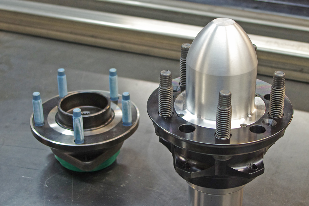
Here is a picture of the two spindle snouts, the 2.0" 5x5 on the left, and the 2.5" GN on the right:
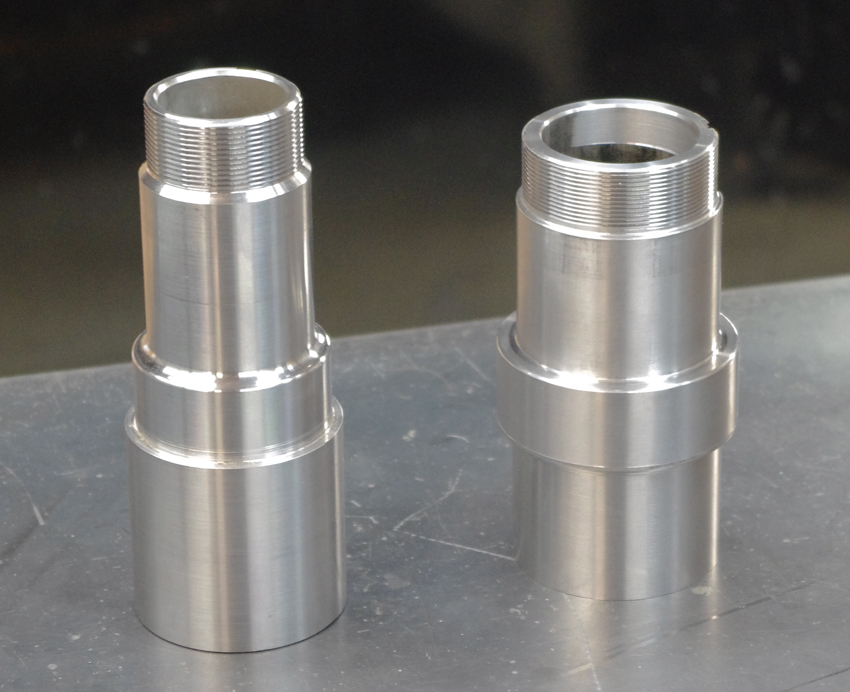
The snouts you see are intended to be welded into rear floater axle assemblies. However they are also used on the front, when welded to a spindle, though some of the material would be machined off.
Since one of my primary goals in designing a spindle is to reduce flex (and thus reduce brake pad knockback), I was initially drawn to the GN snout. With it's 2.5" diameter, snout flex is not likely to be an issue. But I also doubt it would be much of an issue with the smaller 5x5 snout on the left. If these snouts were properly integrated into a spindle assembly, I suspect factors other than snout flex would be at fault it knockback is a problem.
The 2.5" GN snout and bearing package is commonly used on the front in the desert racing community. Though not for Trophy Trucks as much as for buggies. But those guys tend to use a 5x5.5" bolt pattern, so they have their own type of hubs. It is funny that in the circle track world, Speedway Engineering parts are seen as pretty good, whereas in the desert racing world SE is seen as more run of the mill. This could be because in desert racing the vertical loads into the hub predominate (vs. lateral loads) and strength to them is more important than stiffness (the two parameters are not the same). Mittler Brothers makes chrome-moly versions of the GN snout which are used by desert racers.
http://www.mittlerbros.com/snouts-group.html
http://www.mittlerbros.com/off-road-spindle-snouts.html
In this case using 4130 is mostly buying you strength, since it is not that much stiffer than mild steel. But it can be heat treated to be very strong. I've not seen anyone in the circle track community offer snouts out of chrome moly, though there may be some I have not discovered.
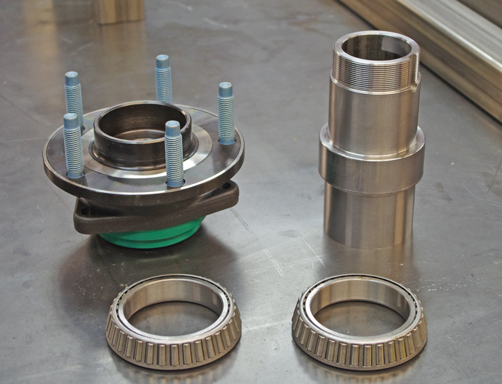
On to the bearings. Here is a pic of the tapered bearings used in the two designs:
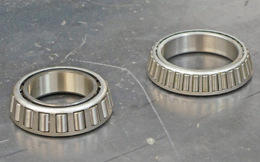
That's the 2.0" ID 5x5 bearing on the left and the 2.5" ID GN bearing on the right. The individual bearings on the 5x5 are much larger (0.375" OD vs. 0.25" OD). The GN has smaller bearings but a lot more of them. Which is better? I have no idea. Perhaps more bearings help spread out the load better? But since they are smaller, and have to travel a bigger circumference, there might be more friction? Since both designs seem to be used very successfully in racing, maybe it does not matter at all.
Another parameter regarding wheel bearings is "bearing spread". This is the distance between the two wheel bearings. There is no consensus on how to measure it. To the outsides of the bearings, the insides, or the centers? I feel measuring to the center of the bearing is most correct. The wider the bearing spread, the lower the load on the bearings due to the torque created on the hub by the tire's lateral force. Here's a very simplistic sketch I made to illustrate this:
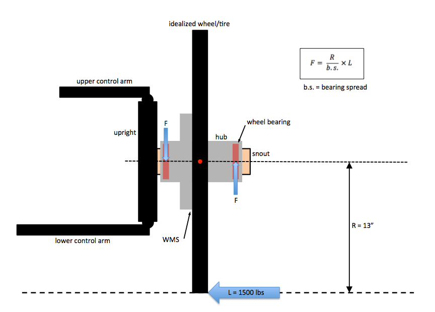
This is an idealized case, where the two wheel bearings are evenly spaced away from the center of the contact patch.
I'll continue in the next post...
05-10-2017 #123 Registered User
- Join Date
- Mar 2010
- Posts
- 469
Given the "L"ateral load of 1500 pounds pushing to the left, I believe your "F"orce arrows are the wrong way. This situation would load the bottom of the inside bearing and the top of the outer. Originally Posted by Dr G
05-11-2017 #124
Starting The Transformation
- Join Date
- Feb 2010
- Location
- El Segundo, CA
- Posts
- 268
The smaller force arrows on the bearings are the "reactive" forces which are created to keep the tire/wheel/hub assembly from going into rotational acceleration. The old "for every action there is an equal and opposite reaction" thing. This is a typical "free body analysis" that would be used in engineering. So in my case I drew the forces exerted by the snout onto the bearings. As you point out there are "equal and opposite" forces exerted by the bearings onto the snout. Originally Posted by bovey
The three Blue arrows shown all create moments (torques) around the red dot. The equation is a simple sum of those torques, which have to equal zero (otherwise the tire/wheel/hub structure start to accelerate). The red dot could have been anywhere. I chose the location to make the equation easier to write.
05-11-2017 #125
Registered User
- Join Date
- Mar 2010
- Posts
- 469
Originally Posted by Dr G
OHhhhhh... Gotcha. Thanks for clarifying.
05-11-2017 #126
Starting The Transformation
- Join Date
- Feb 2010
- Location
- El Segundo, CA
- Posts
- 268
Continuing on from my previous post. This is the equation for the forces on the wheel bearings due to a lateral load at center of the tire contact patch:
F = the force on each wheel bearing
R = the radius of the tire
L = the Lateral Load at the tire contact patch
b.s. = the bearing spread
This equation allows a "sensitivity analysis". Something done in engineering just to get a "feeling" for how one parameter depends on another. It is not meant to be 100% accurate of real life.
Assume a 3000 lb Pro Touring Truck in steady state cornering. It's Bovey's truck, so it has a 50/50 weight distribution, and thus 1500 lbs on the front axle. Just to make things easy we have 100% weight transfer at the front axle (the front inside tire is just off the pavement). And we have sticky tires to allow us to corner at 1g. The Lateral Load is thus L = 1500 lbs
Assume a typical Pro Touring tire with a diameter of 26", so R = D/2 = 13"
Let's start by assuming a bearing spread of 2". This results in F =9750 lbs. The vertical force on each wheel bearing due to tire lateral load is 9750 lbs. Note that this is much larger than the lateral load on the bearings, which is simply equal to L, and is 1500 bs. Actually only the inside bearing is able to bear any of the lateral load btw, the outer bearing is just floating in this respect.
If we halve the bearing spread to 1", the force on the bearings double to F = 19,500 lbs. So that is the "sensitivity. The bearing force is proportional to the inverse of the bearing spread. For every 10% that you increase bearing spread, you will decrease the vertical bearing load by 10%.
Note I have ignored the additional vertical force on the bearings due to vehicle weight (the pavement pushing up on the tire/wheel/hub). This force is independent of bearing spread, and in this example would be 1500 lbs (total on both bearings), much smaller than the forces created by the lateral load.
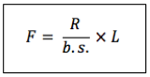
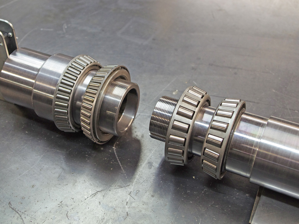
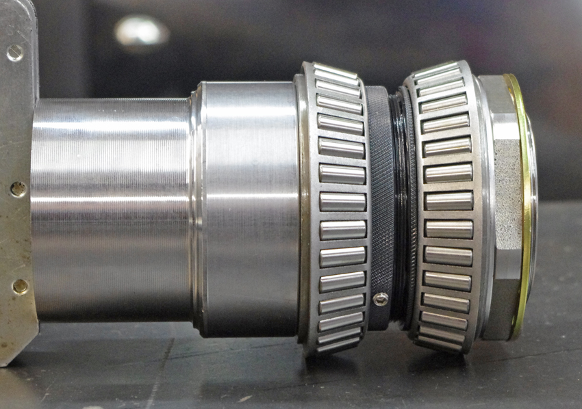
Here is a picture showing the measured bearing spread of the GN 2.5" bearing/snout vs. the 5x5 2" setup. The bearings are place on the snouts pretty much where the wheel hub would locate them:
The difference turned out to be smaller than I expected. Moving from the GN design to the 5x5 yields an increase in bearing spread of 27%, and thus, in my idealized analysis, a 27% reduction in bearing load caused by tire lateral force. Not a huge change, and probably not big enough to warrant choosing one design over the other unless you were really stressing your parts to the limit.
So my boring conclusion is that I have no conclusion. The two bearing packages are different, and probably offer advantages or disadvantages in certain situations. But the differences are likely to be small. Fyi, any differences in weight between the snouts, bearings and hubs of the two designs is quite small, and not worth basing a decision on.
One other thing I have thought about is the comparison of tapered bearings vs. round bearings for a wheel bearing application. Is one better than the other? Round bearings have a smaller contact area, and should have less friction. At least until they are heavily loaded, at which point the smaller contact area might "dig into' the race a bit more, creating added friction. Tapered bearings have a reputation for handling large lateral loads, but the large contact area would seem to point to higher friction, at least in low load situations. I know at one point in the 70's when I was very into BMX, there was a sudden push to move headset bearings to a tapered design (the part that holds the fork to the frame and allows one to steer the bike). But this effort petered out, and to this day bicycles use round bearings in the headset. However this is an application which is extremely sensitive to friction. If you've ever ridden a bicycle with the headset bearings adjusted too tightly you know, it is very difficult to balance the bike. Without more education I can't even speculate on round vs. tapered bearings, and which is better for a wheel bearing application.
Since every thread is better with pictures, here's a few more:
05-11-2017 #127
Registered User
- Join Date
- Sep 2011
- Location
- Southern Ontario
- Posts
- 640

Interesting stuff Gustave, I appreciate the write up and nice pictures to boot!
05-11-2017 #128
Starting The Transformation
- Join Date
- Feb 2010
- Location
- El Segundo, CA
- Posts
- 268
Thanks. I hope this of interest to some people, now or in the future. Originally Posted by Peter Mc Mahon
05-11-2017 #129
Starting The Transformation
- Join Date
- Feb 2010
- Location
- El Segundo, CA
- Posts
- 268
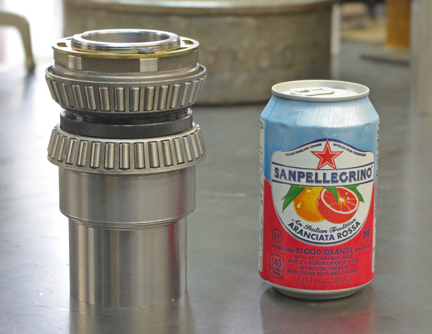
One last item regarding the 5x5 and GN bearings. There is this little do-dad:
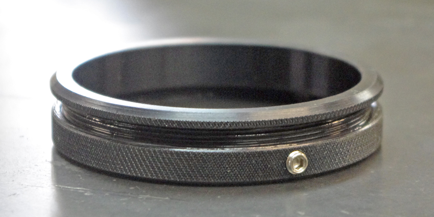
This is called a "bearing spacer". I first heard about these when I was chatting on the phone with Ken at Speedway Engineering about ways to reduce brake piston knockback on floaters. At the time I heard what he said, but had no idea what he was talking about. It took me a bit of thinking to realize how these bearing spacers actually work.
Think about the typical way one would adjust pre-load on the front wheel bearings, and then insert a cotter pin to keep the retaining nut from backing out. That retaining nut is not really tight. In fact it is merely hand-threaded onto the spindle snout until it just kisses the wheel bearing. Now think of the action of threading a (non-locking) nut onto a bolt. If you carefully jiggle the nut you can feel that it moves a tiny bit. It has to by definition, otherwise you would never be able to thread the nut onto the bolt by hand (it would be an interference fit).
If you were to subsequently thread a second nut onto the bolt and tighten them against each other with wrenches, you would no longer be able to detect any movement at all in either nut. All play will have been taken up by the action of pushing the nut threads against the bolt threads.
The same situation presents itself on a front spindle snout when you adjust the wheel bearings. The nut it never really tightened against anything, so there is this small amount of play present.
The idea behind bearing spacers is that they fit between the inner bearing races, and as you tighten the retaining nut against the outermost inner wheel bearing race, it pushes against the bearing spacer, which then pushes against the inner-inner wheel bearing race, which is bottomed out against the end of the snout. The net result is that you can tighten the retaining nut to 100 ft lbs (as is often recommended), and still achieve perfect wheel bearing adjustment. The trick is that the bearing spacer is adjustable for length, and you have to fiddle with the size of the bearing spacer through trial and error to get the adjustment just right. But when it is right, you can just crank the retaining nut right down and there is not more play in the nut. Hope this makes sense. DRP seems to be where circle track racers get their bearings spacers. They were the recommended source by Ken at Speedway.
Here is a video on the DRP website showing how the spacers work and how to adjust them:
https://youtu.be/ezDmH9iFsYI
Here is a picture of the 2.5" GN bearing spacer installed between the bearings:
05-11-2017 #130
Starting The Transformation
- Join Date
- Feb 2010
- Location
- El Segundo, CA
- Posts
- 268
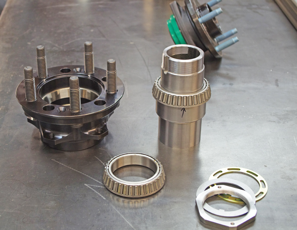
Couple things I forget to mention. These Grand National and 5x5 hubs come with 5/8" studs, not 1/2". The thread can be fine or coarse (as in the photos). I plan to install ARP studs with an extra long shank so that the brake hat and wheel are not pressing against the threads of the studs, but against the shank. Just seems the right way to do things.
The dust caps, which attached with 3 or 4 screws depending on brand, are 3.06" OD. Larger than the common Corvette size of 2.78" but not totally unheard of. The pointy dust cap is meant to speed installation of wheels during pit stops. I prefer the look of the flat ended dust cap.
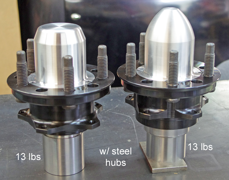
Note that each design, when completely assembled, weighs 13 lbs. This vs. a Corvette ZR1 hub which weighs 8 lbs. So a 5 lb difference. But I have steel hubs at my disposal. One can purchase identical aluminum hubs which weigh about 3 lbs less. This narrows the gap to 2 lbs, which you can easily loose or gain just be changing tire type. And many folks in the Pro Touring realm would happily kiss away 2 lbs on each wheel just to get a particular "look" (I probably fall in that camp).
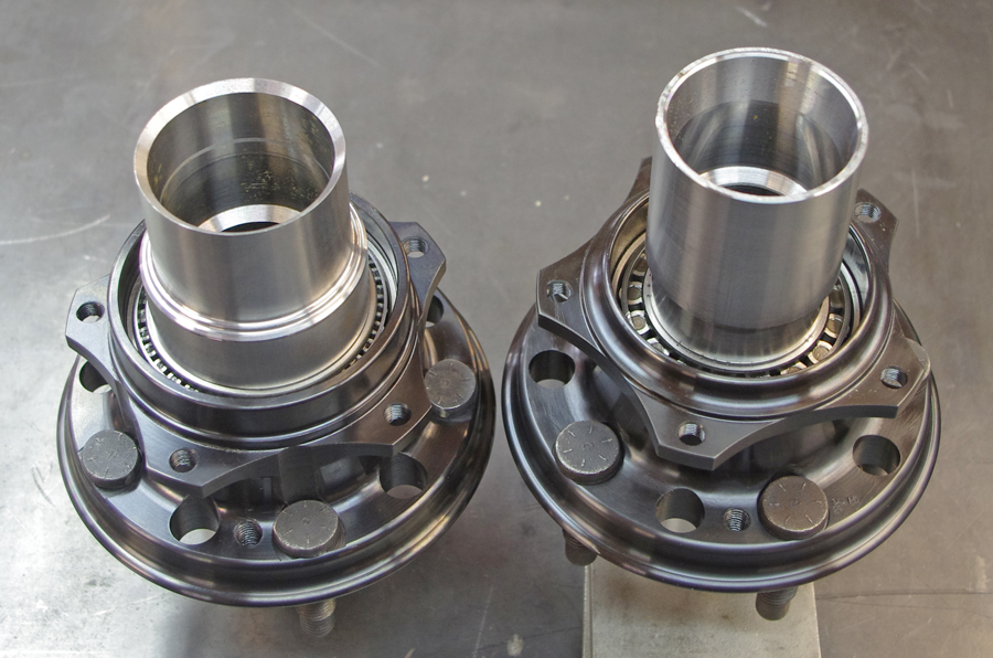
Regarding steel hubs vs. aluminum hubs. Aluminum is lighter, but is also less strong, less stiff, loses both strength and stiffness as temps increase above 250 deg, and the hubs expand more as they heat up, thereby changing the bearing preload. So not a slam dunk necessarily.
In particular regard to knockback induced by flex, the larger 2.5" GN hub might actually present a better design when going with aluminum. The larger diameter of the "barrel" of the hub means the wheel mount surface is better supported as the wheel pushes on it and tries to flex it (thus moving the rotor relative to the caliper). You can sort of see this in the pics:
05-13-2017 #131
Starting The Transformation
- Join Date
- Feb 2010
- Location
- El Segundo, CA
- Posts
- 268
I did some research into the bearings of the 2.0" 5x5 design vs. the 2.5" GN designs.
The 5x5 bearing has a part number 368A with a corresponding race p/n of 362A
The GN bearing p/n is L610549 with a race p/n L610510
Here are the dynamic load ratings for the two bearing types:
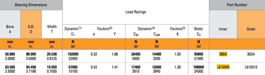
One can see that the 2.0" 5x5 bearings have a higher dynamic load rating than the GN bearings, both radially and in the axial (thrust) direction.
If you, like me, are not familiar with the way the load ratings are expressed, here's an explanation:
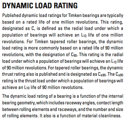
Based on this it seems the C90 and Ca90 ratings are the ones to focus on. And in this respect the 2.0" 5x5 bearings have a 52% higher radial and 14% higher thrust load rating than the 2.5" GN bearings. That is something you might hang your hat on.
05-14-2017 #132
Registered User
- Join Date
- Mar 2010
- Posts
- 469
This is very interesting stuff. I'm looking into the DRP spacers and bearings at the moment. I questioned the import bearings that came with my floater. "Everyone" says they are "fine". I really don't get why manufacturers skimp on the bearings, it's a difference of $50-$100 on a brutally expensive part.
Also, FWIW, it's a nice dream that my truck will way 3000lbs and have a 50/50 weight distribution, but no, nope, huh-uh, not very likely.
Thanks again for taking the time to write these posts, very cool stuff.

 Reply With Quote