Results 41 to 60 of 132
-
10-02-2015 #41
 Registered User
- Join Date
- Jan 2015
- Location
- Mountains of AZ
- Posts
- 21

 Originally Posted by Dr G

Cool. Build is looking really goodMy finished daily
1966 Fairlane
306 with 4R70W
QA1 Coilovers,vintage air,
Current project
1948 Ford F1
Lexus SC400 IFS
DOHC 4.6 with 4R70w
-
10-13-2015 #42 Starting The Transformation
- Join Date
- Feb 2010
- Location
- El Segundo, CA
- Posts
- 268
A few quick update pics...
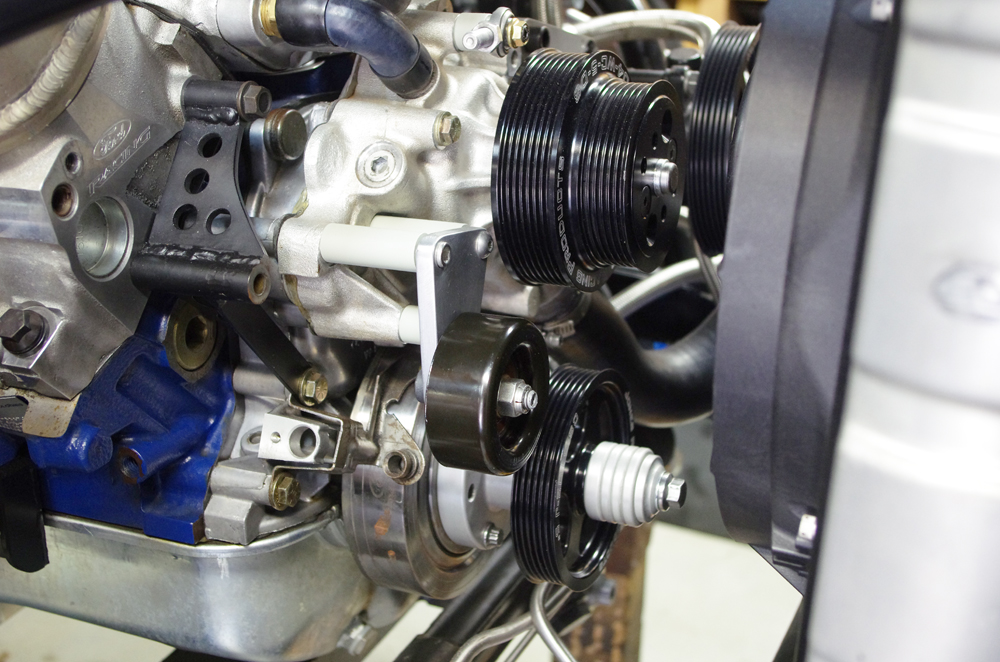
During the upgrade from C4 to AODE I decided to install the Jones Racing pulleys I had lying around. Since this is kind of a home brew, using my alternator and my power steering pump (not theirs) I had to figure out how to configure things. I decided to add an idler pulley so that the alternator would pulley would have enough 'belt wrap'. I made a little bracket for the idler which you can see here:
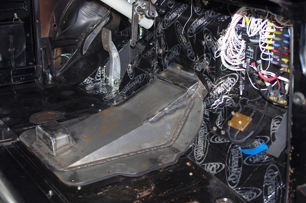
Since the AODE is bigger than the C4 I bought a new trans cover plate from Mid 50's. It's the one they have for aftermarket transmissions, but I still had to modify it further to get enough clearance. I also had to add a little hump to accommodate the vent line for the trans. I wanted to vent it to a catch can. I once had a trans overfilled and the extra fluid dripped down on to the exhaust create a ton of smoke. Of course this happened as a tuner friend and I were cruising around trying to tune for drivability. Like flooring it up the Sepulveda Pass on the 405 at 80 mph, smoke billowing out the back all the while. It was quite a spectacle and I decided right there I would never let it happen again.
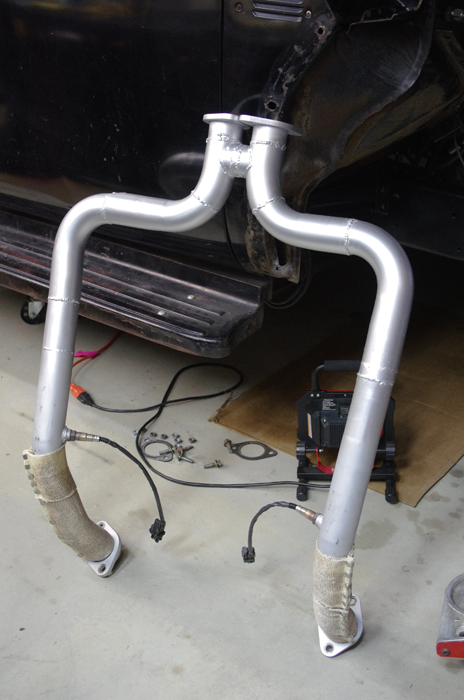
Because of the large pan on the new trans, the exhaust would not clear, so I had to rework it. I sort of half-assed it, as I did not want to get into modifying the rear portion, only the front which I had removed already. I'll do a more proper job when I build the new frame later on:
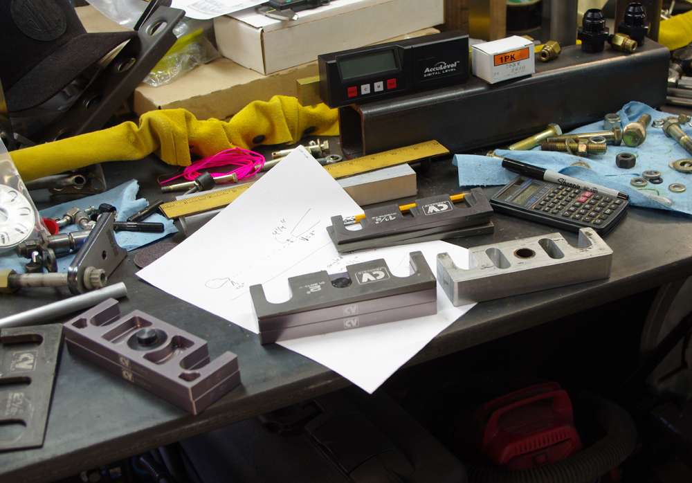
New longer transmission means new driveshaft. As I was measuring driveline angles I discovered some alarming things the last builder left me with. Like a rear U-joint operating at three times its max allowable angle! I tried to correct things as best I could with shims, but there's only so much I can do without rebuilding the whole rear axle assembly. Again, that will have to wait for the new frame build. Here's a pic of the shims. I have truck arms btw, hence the shims. With a 3-link I would just be adjusting rod ends.
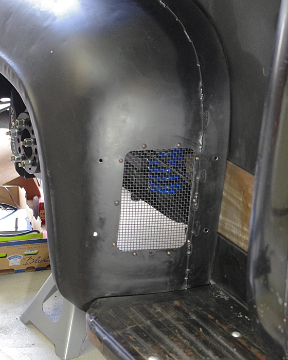
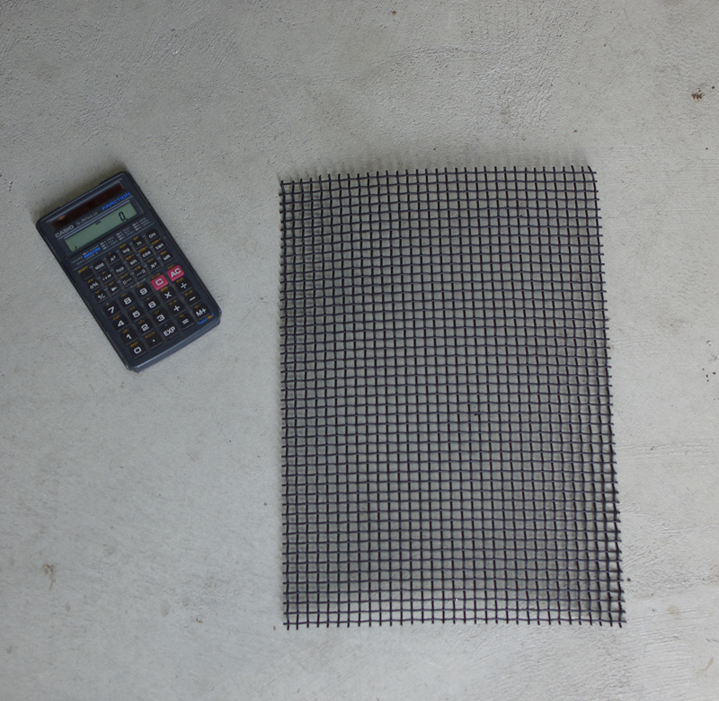
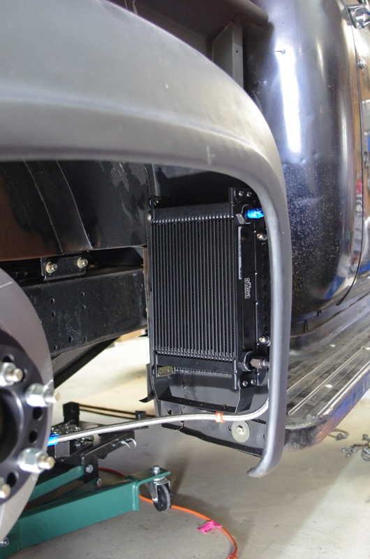
Lastly, I am installing a proper trans cooler which I showed before. I am mounting it in the rear passenger fender. Here is the opening I cut and the screen mesh I installed to stop debris from damaging the cooler. The mesh is stainless painted black.
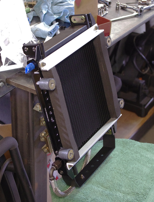
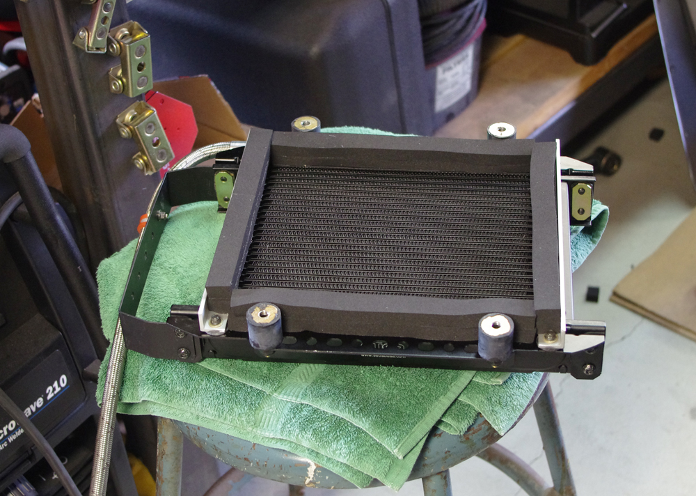
Here are some pics of the cooler all mocked up with mounting brackets, rubber mounts, shrouding and one cooler line:
And here you can see it mounted inside the fender:
More to come... Gustave
10-26-2015 #43
Starting The Transformation
- Join Date
- Feb 2010
- Location
- El Segundo, CA
- Posts
- 268
A few more pics...
Here is a another shot of the serpentine belt system I cooked up using some parts from Jones racing:
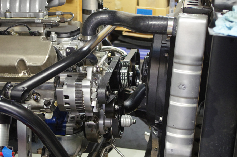
I did not try to do a true one-piece serpentine belt. That was not really my goal. But I did want to use ribbed belts because they reportedly require less tension than V-belts. And I've always disliked how tight V-belts have to be to stop slipping. I just feel it places a ton of load on the bearings, and it also leads to flex in the mounting systems, which induces more slipping and squealing. I added the idler pulley to increase the belt wrap around the alternator pulley. The alternator is driven faster than the water pump or PS pump, and therefore is most likely to slip. Increasing belt wrap is like bigger tires, more friction, less slipping. Also, the mandrel on the crank will allow me to easily add pulleys for AC or even dry sump in the future.
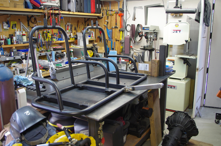
Here is a photo of the seat mounting base I fabled up:
I was laughing so hard when I took this pic I'm surprised it is not blurry. That is because I had just bolted on the brace for the shifter and parking brake. And until then I had not realized how funny it would look sticking out like that. However, the shifter brace still had some work to be done, and once it is installed in the truck with the shifter and parking brake it will be less noticeable:
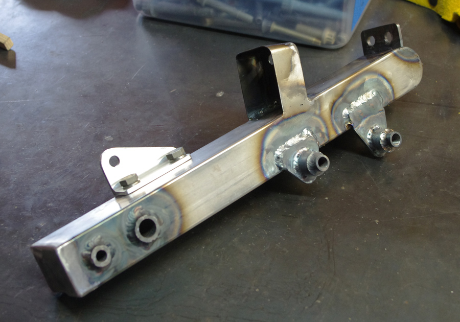
Here is the brace after I welded on the required mounting points for shifter and parking brake:
The seat mounting base shown above sitting on the work bench is sort of an odd thing. I never really intended for it to end up like this. I was originally trying to get the seats to mount lower in the cab than was possible with the previous square tube aluminum base I had made. Then I wanted to add shoulder belts, but was not comfortable just bolting them to the back of the cab, so I figured I would add some tubes to help strengthen the belt mounting points. Then I wanted to add some handles to help in getting in and out of the bucket seats, which are quite deep. And in the end this is what I got. Unfortunately it weighs 46 lbs, where the previous aluminum seat base was 21 lbs. But several mockup trials did show it makes it a lot easier to get in and out of the truck.
I've started wiring the transmission up to the PCS controller. PCS (Powertrain Control Solutions) would have you drill a hole in the firewall and push the (rather large) connectors through the hole, then add a grommet. That's great for folks who don't like to work on wiring, but was not really the ideal way to do it. I've decided to mount the control between the seats for easy access. So I decided to add a bulkhead connector just behind the trans, at the front of the seat base, and then splice the wiring harness into both sides of this connector. I chose a mil spec connector, because I find them easy to work with, they look good, and they are bullet proof.
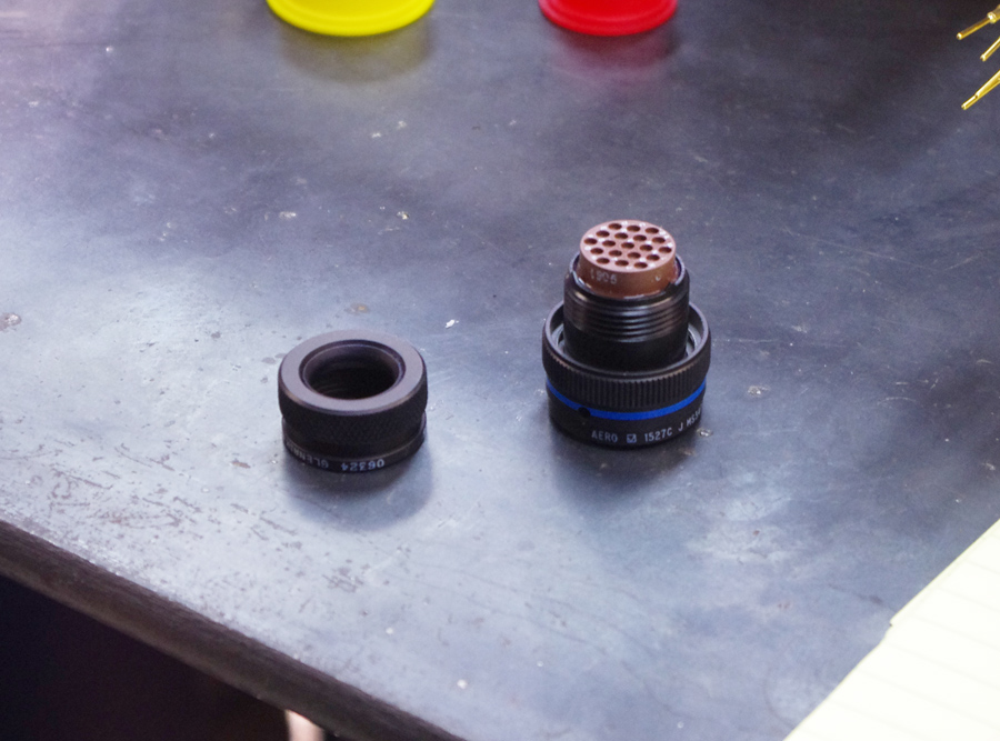
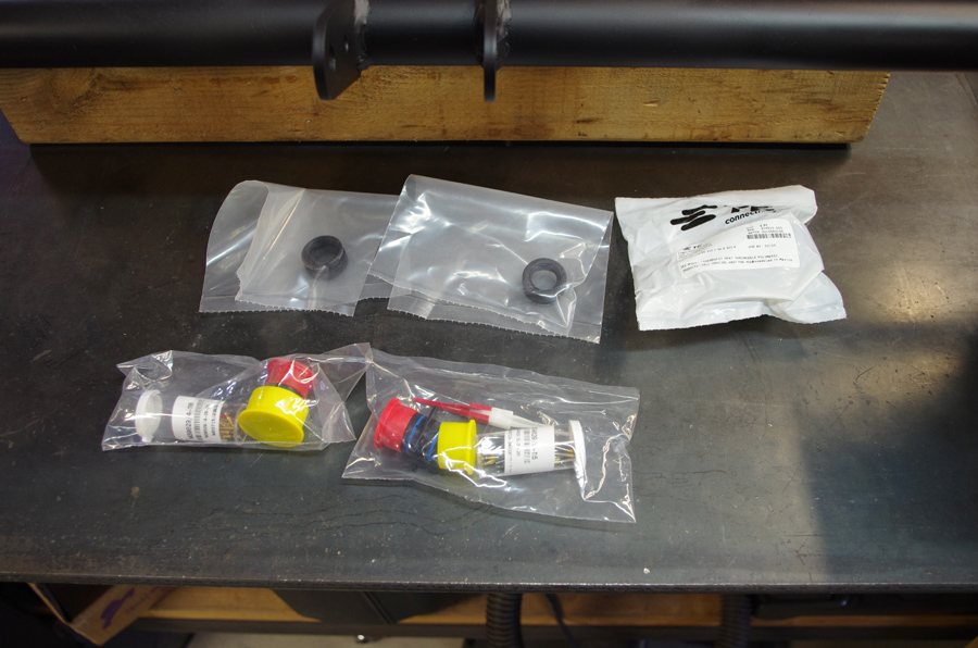
I generally use Mil-C-26482 Series-II connectors, because they are easy to get, relatively inexpensive and available in a lot of configurations. I really only use the wall mounting receptacle with narrow flange (MS3470) and the straight plug (MS3476). I prefer to spec the pins on the plug side and the sockets on the wall mount side, though you can do it the other way around too. Next to the connector is the "backshell". In this case it is what they call a "shrink boot adapter". The connector should always be used with some type of backshell, as it pushes the rubber center tight around the wires. But most of the common backshells are for wiring systems with 'open' wires, as opposed to jacketed with heat shrink. Shrink boot adapters used to be hard to find. One of the only place that makes them is Glenair, out of Glendale CA. But now there are online places catering to automotive wiring specifically, and they stock them.
When you buy the connectors they come in little packages with the associated pins or sockets and a pin insertion/extraction tool (they red and white plastic thingy).
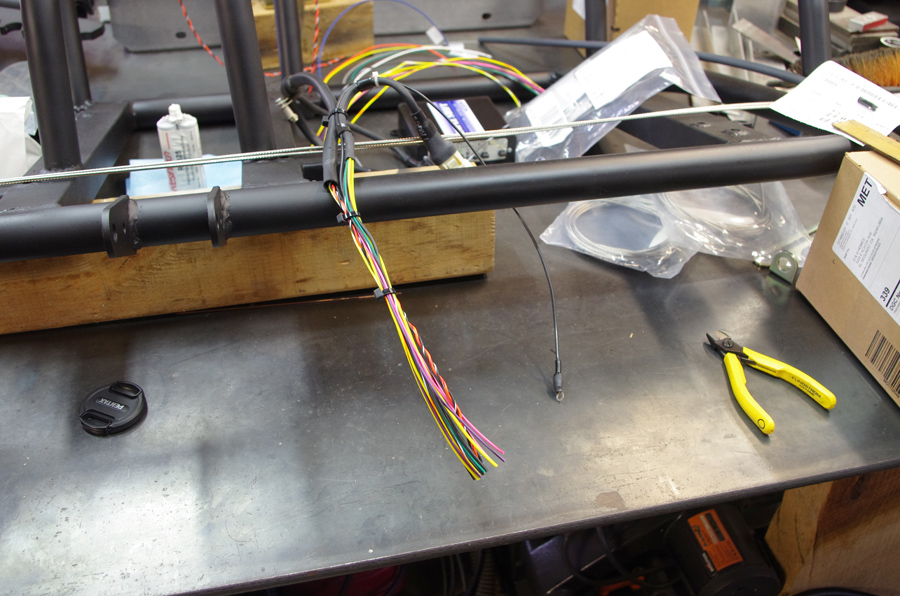
Here is a shot of the transmission-side of the PCS harness, which I cut into two halves, the outdoor part and the indoor part:
Now the same wires, after they have been stripped, and the mil-spec pins crimped on:
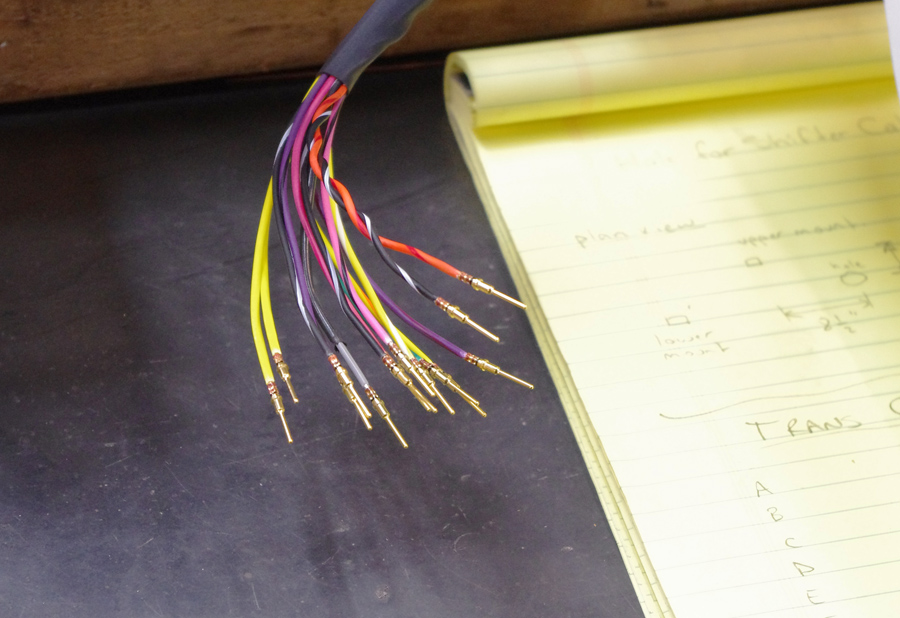
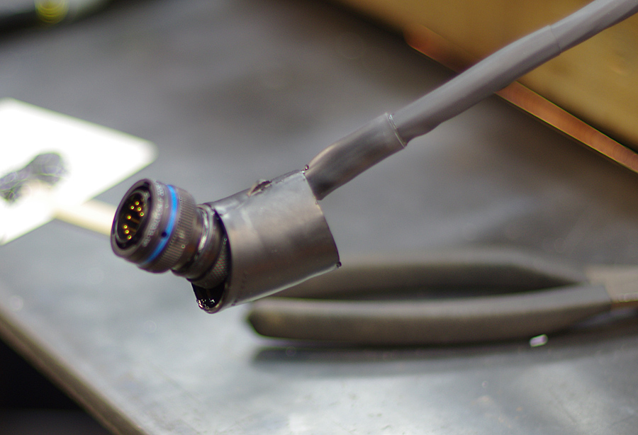
And now with the pins inserted into the plug connector, and the backshell screwed on:

Note the pieces of unrecovered heat shrink around the wiring bundle. When doing these connectors you have to think ahead and slide on any and all things you'll need that won't fit past the connector - before you add the connector. That includes the backshell, but usually not the shrink boot. More about that part now.
At this point the wires in the harness will be completely covered in heat shrink, except for right near the connector. That is where the shrink boot comes in. It attaches the heat shrink jacket to the connector, making a continuous system. Here is a pic of a shrink boot fresh out of its package:
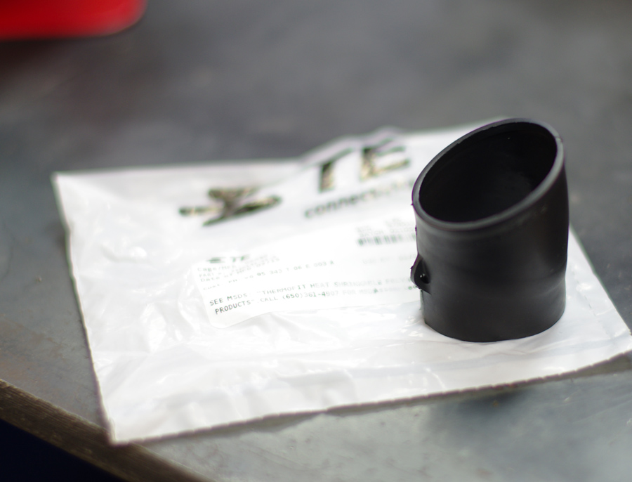
These things are pretty funky. They are only made by two or three companies in the world, Raychem being the most common here in the U.S. In theory they come in a lot of different configurations of material, with or without adhesive. But generally cross-linked or regular polyolefin is what you want, without adhesive, as you add that separately. The adhesive is a special two-part epoxy that comes out of England and costs about $50 per tube, though I've been using one tube for about 10 years (I keep it in the fridge in-between uses). The epoxy is critical for two reasons: 1. it bonds the shrink boot to the heat shrink jacket and the connector backshell and 2. it provides lubrication to allow the shrink boot to move around as it shrinks (and it moves around a lot).
Here's come before and after shots of a 90 deg shrink boot before and after "recovery" (shrinking):
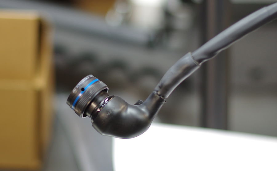
It takes an amazing amount of heat to shrink one of these buggers down. Like 5 minutes of fully directed heat. But as long as the boot continues to change shape, keep heating. Wear gloves so you can reposition it as it shrinks. Once done and it cools off it is amazingly solid. What this does is provide the holy grail of mil spec wiring - strain relief. It prevents and movement of the wiring bundle from slowly strain hardening the wires at the connector entry point. Hence high reliability in extreme vibration environments.
So, here is my trans harness when all was said and done:
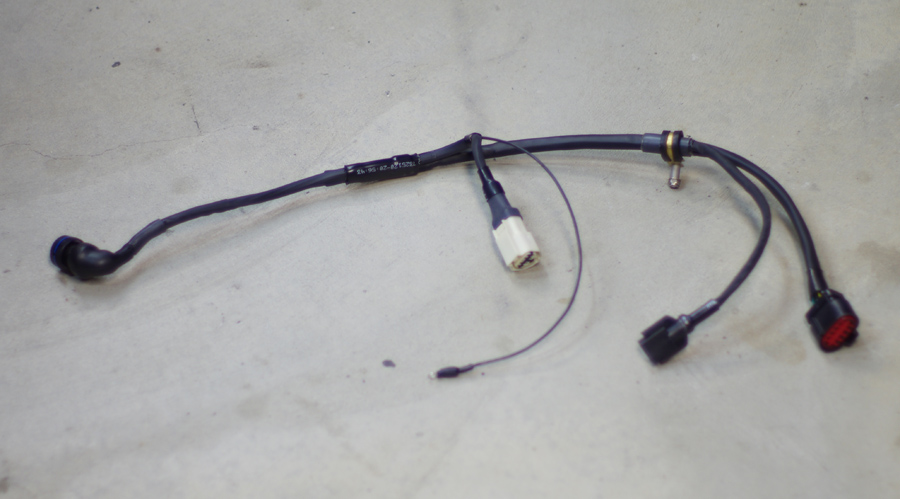
The harness is routed using a couple of Adel clamps attached to the transmission. The keeps the harness in place and prevents the 'weight' of the harness from straining the connector areas. There is enough slack in the harness to undo the various connectors, but no more. 'Clean and tight'.
More to come.
10-27-2015 #44
Registered User
- Join Date
- Sep 2011
- Location
- Southern Ontario
- Posts
- 640

Nice write up. I am planning on doing something similar, but I'm terrified of cutting my perfectly good harness!
10-27-2015 #45 Registered User
- Join Date
- Feb 2005
- Location
- Minneapolis, MN
- Posts
- 195
Awesome wiring harness. I've been toying with idea of trying some of those mil-spec connectors. Do the pins take a special crimping tool?
Also, for your seat mount, if the sides are just grab handles, you could always go to town with a drill bit, and take some weight back out. But just for the handles, not the base or the belt mounts. Just an idea.
10-27-2015 #46
Starting The Transformation
- Join Date
- Feb 2010
- Location
- El Segundo, CA
- Posts
- 268
Yes, it is a bit freaky to cut up a good harness. But after that first snip it gets easier. Go for it! Originally Posted by Peter Mc Mahon
10-27-2015 #47 Registered User
- Join Date
- Aug 2007
- Location
- Roanoke (FortWorth) Texas
- Posts
- 786
Nice build. Love the details
ChrisTotal Cost Involved - Ridetech - Fatman - Total Control Products - Gateway Performance - MaverickMan Carbon
10-27-2015 #48
Starting The Transformation
- Join Date
- Feb 2010
- Location
- El Segundo, CA
- Posts
- 268
They are indeed grab handles, but, they are also supports for the shoulder harness bar. To prevent that bar from just folding forward in a crash. I did add attachment points at the top of the shoulder harness bar where it will screw to the back side of the cab, but I was not convinced that would be sufficient. In fact those tabs at the top of the shoulder harness bars are more intended as a mounting point for headrests, which I plan to build. Right now if I get rear ended my head will hit the back glass instantly, there is no way around it. I'd like to fashion some thin headrests to put a layer of aluminum and dense energy absorbing foam between my head and the glass. Far from perfect but better than nothing. Originally Posted by brawls43
In any case, the grab handles are fashioned from 0.065" wall DOM and don't weigh that much. The bulk of the mass is in the periphery tube that forms the base, which is made from 0.109" DOM. Since it spans across the two mounting points to the cab, I did not want it flexing down in the middle, so made it thicker. It is what it is for now, I'm adding a lot of weight in terms of sound/thermal proofing too. A "lightweight special" is not in the cards I suspect. I'll just do what everyone does, and add horsepower and bigger tires to try to combat mass 8^)
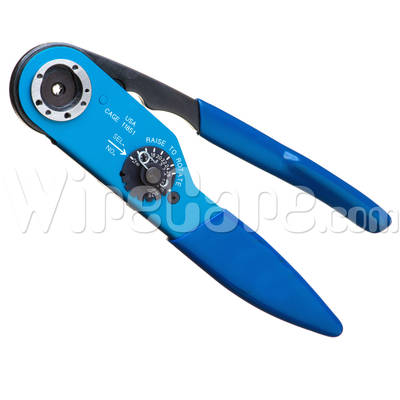
On to wiring. The crimping tool for mil spec connector pins is made by Daniels Manufacturing Co. (DMC) in Florida. As far as I know that is the only company who makes it, it is the only one I've ever seen people use in any case. You need the tool and what they call the turret.
This is the tool:
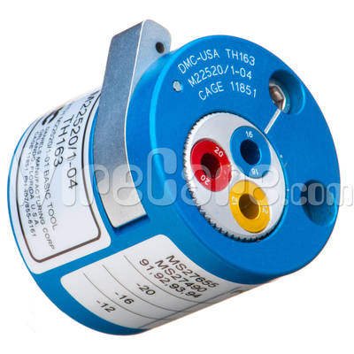
And this is the 'turret':
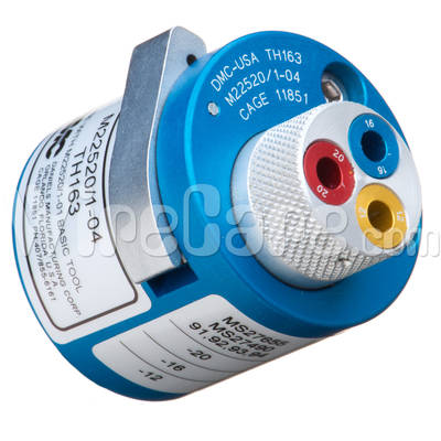
The tool has two adjustments. The turret is where you stick the pin or socket that you are crimping onto the wire. The turret accommodates wire gauges from 12 GA through to 20 GA in pairs. That is because the pins and sockets are made in various sizes, but each size will fit two different wire gauges. This is common and you get used to it in "wire terminal world". Yellow designates 10GA and 12GA, Blue designates 14GA and 16GA and Red designates 18GA and 20GA.
The same standard applies to the mil spec connectors. A connector for 14GA wire will be exactly the same one as for 16GA wire. I suspect this was done (a) because it could be and (b) because it reduces the quantity of part numbers floating around the already crowded mil spec system.
So, you set the turret for the pin or socket size you want to crimp (10/12, 14/16 or 18/20) and then you push it inwards to "lock" it as shown in this pic:
Now you have to set the tool to the correct crimp depth. This is done with the black knob at the middle of the tool. This is set for the specific wire gauge, no pairing, and it simply limits how far the tool ratchets down onto the pin or socket before it releases. Thus establishing the crimp depth. The beauty of this tool is it crimps down onto the pin or socket from four directions at once (vs. just one or two). It practically fuses the metal of the terminal into the wire.
There is a ton of info about this on the web, just scratch around and look for instructions or procedures. I had to figure it all out myself about 10 years ago (with some help from Neel Vasavada at Apex Speed Motorsport), but today it's trickling down more and more. Different hobby-type guys like me are doing it and reporting their knowledge, which helps others.
The DMC crimp tool is not cheap. If you buy it new figure close to $400 for the tool and turret. If you go with 22 GA or thinner then they make a separate smaller tool and turret. I generally don't go thinner than 20GA but in upper levels of motorsport they'll go to 26GA or thinner for low current sensors to try to save weight. No thanks. Satellites will go into the 30's on wire gauge, and also they run at 100V to allow smaller wire sizes, all to save weight.
You can search for a used tool on eBay, or some places will sell surplus tools. But really it is an investment in my opinion. Once you can do your own high quality wiring, it really frees you up. And, the same tool can be used to crimp contacts on the Deutsch DT and DTM connectors:
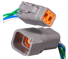
These are the next best think to a mil-spec bayonet connector. Very high quality and easy to use. I wish all automotive sensors accommodated these, it would make wiring so much easier. Here's a place that specializes in Deutsch DTM, but there are many other places to get them also:
http://www.deutschconnector.com
I could go on and on about this. I suppose some folks think I already have!
Gustave
10-27-2015 #49
Starting The Transformation
- Join Date
- Feb 2010
- Location
- El Segundo, CA
- Posts
- 268
OK, so after I blabbed on about the DMC crimping tool and how to use it I find this handy video explaining it much better:
https://www.youtube.com/watch?v=6Du-cvKsQOE
Note that the turret shown actually goes down to 24GA wire. I'll have to look at my tool to compare. But I know I used to have the smaller DMC crimper (which they show at the end of the video) that was intended for smaller wire sizes.
10-28-2015 #50
Registered User
- Join Date
- Jun 2008
- Location
- Jacksonville, FL
- Posts
- 14
May I ask what EFI setup you used and how you like it? Originally Posted by Dr G
10-28-2015 #51
Starting The Transformation
- Join Date
- Feb 2010
- Location
- El Segundo, CA
- Posts
- 268
I am using a Vipec V88 ECU. These come out of New Zealand, reportedly designed by some ex-Motec guys. Originally Posted by Alpina
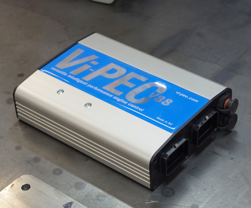
I have no issues with it. I bought it because it was more affordable than a Motec ECU, though I'd probably prefer to have Motec simply because it is so widespread and many people are familiar with it.
A lot of folks have success with MegaSquirt, which seems to have a large online support community, which can be very helpful.
Some of the "V8-based" ECUs seem to be maturing, like FAST or Holley.
At the end of the day any ECU does basically two things: control fuel and control spark. The rest boils down to user interface and sophistication of drivability tuning. And maybe things like transmission control, traction control, boost control, anti-lag etc, assuming you might need those.
Gustave
10-28-2015 #52
Registered User
- Join Date
- Feb 2005
- Location
- Minneapolis, MN
- Posts
- 195
Valid point on the seat brace, I didn't think about that.
Thanks for the info on the wiring, do you have any links you recommend to source the connectors or pins? Definitely going to look into getting one of those crimpers, especially if I can find one used and use it with Deutsch connectors too.
Nice ecm, I've read good things about the ViPEC's. HP Academy has some decent info on tuning with those, they're big Motec guys.
10-28-2015 #53
Starting The Transformation
- Join Date
- Feb 2010
- Location
- El Segundo, CA
- Posts
- 268
Thanks for the tip on HP Academy, I was not familiar with them. Originally Posted by brawls43
Here is a link to PEI Genesis, where you can get just about any military MIL-C-26482-II style connector with contacts. They come in Olive, Black or Nickel coating. You can narrow down the selection at the left (I already narrowed it down quite a bit).
http://www.peigenesis.com/en/shop/f/...elding_i:(410)
Here are a couple or places aimed at the motorsport market:
http://milspecwiring.com/store/index...te=common/home
https://www.prowireusa.com/default.aspx
There are others I'm sure. I know there was a place in Indiana (near the Indy track) and another place in El Cajon (San Diego) that catered to the off-road racing market. Don't have the links handy.
Gustave
11-18-2015 #54
Registered User
- Join Date
- Feb 2005
- Location
- Minneapolis, MN
- Posts
- 195
Thanks Gustave, found an ebay deal on a crimper and turret. Now to figure out what connectors I need. I like how the PEI Genesis page lists the mating connector. The two motorsports don't seem to be laid out quite as nicely.
Great video too btw, thanks for posting this info.
11-18-2015 #55 Registered User
- Join Date
- Mar 2010
- Posts
- 469
Gustave, awesome. Love your sensibilities. One thing, are you going to put some kind of protection back side of your cooler in the fender? I know it seems crazy, but tracks are never as clean as you think and once the tires are hot they throw around a lot of crap. My 3 years of track/AutoX/Rally has done more sandblasting in my wheel wells and rocker panels than the previous 15 years of driving. That is a nasty place to damage a cooler. Love the build.
11-19-2015 #56
Starting The Transformation
- Join Date
- Feb 2010
- Location
- El Segundo, CA
- Posts
- 268
Excellent point. I've picked my share of balled up rubber out of cars after track days and wondered how the heck it got there. My little voice has been telling me to add protective screens to both the coolers I added inside the wheel wells, so I probably will once I get the thing on the ground and running.
Gustave
11-20-2015 #57
Starting The Transformation
- Join Date
- Feb 2010
- Location
- El Segundo, CA
- Posts
- 268
A few small update pics.
Here is the PCS Smart-Shift transmission controller installed next to the driver's seat:
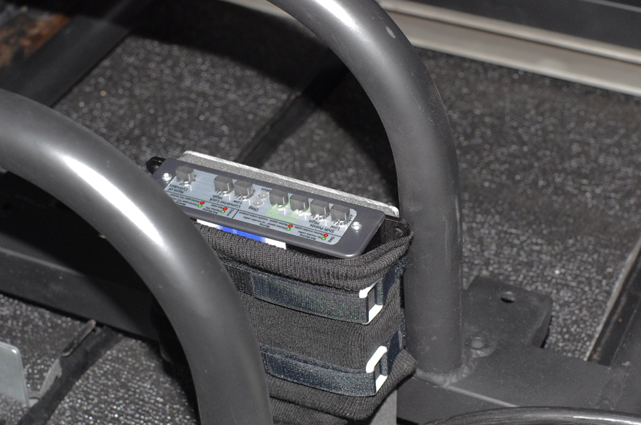
I figured it would be good, at least initially, to be able to easily fiddle with the various knobs that control shift performance (RPM, firmness etc.)
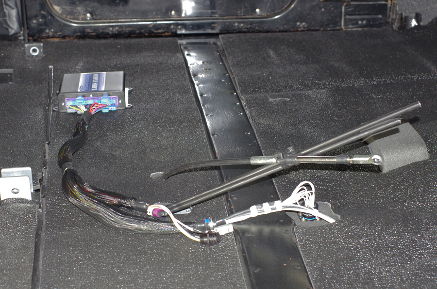
Here we can see the wiring extending out from the PCS controller, the connector that leads to the transmission, as well as under the floor mat towards the firewall:
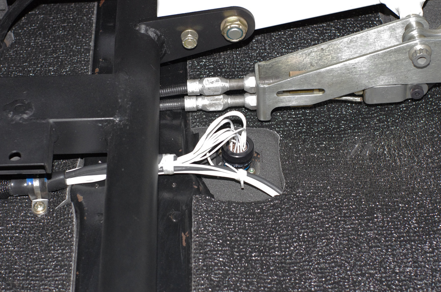
Here's a closeup of the connector:
This photo shows the mount I made for the shifter and handbrake. Previously these had been mounted to the transmission:
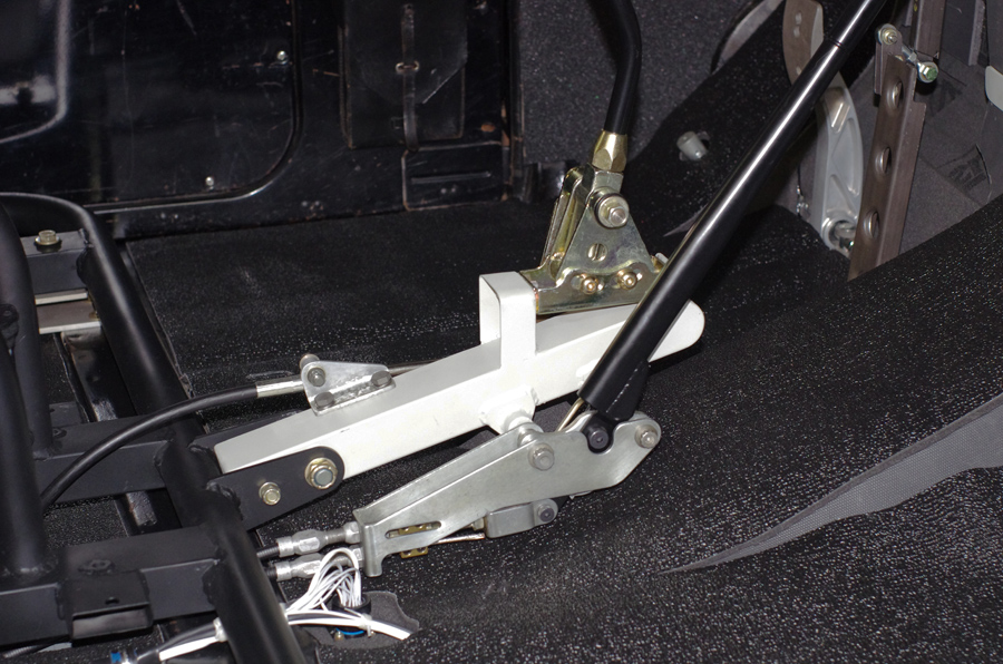
I like the idea of a cable operated shifter as it gives the option of mounting it higher up, without resorting to a super-long (hence vague) shift lever. I know it's just an automatic, but it still feels reassuring when the shifter solidly clicks into the next gear. The handbrake used to be too hard to reach, way down near the firewall, so this gets it a lot closer.
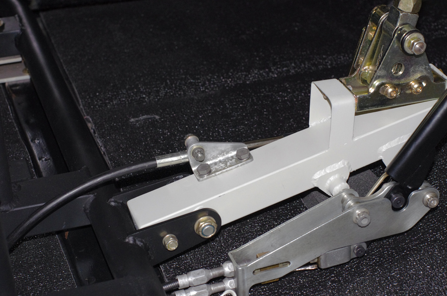
Here's a closeup. Note the care taken with every single fastener in terms of how it looks, and how long it is (protrusion). I just have a thing for that, no idea why:
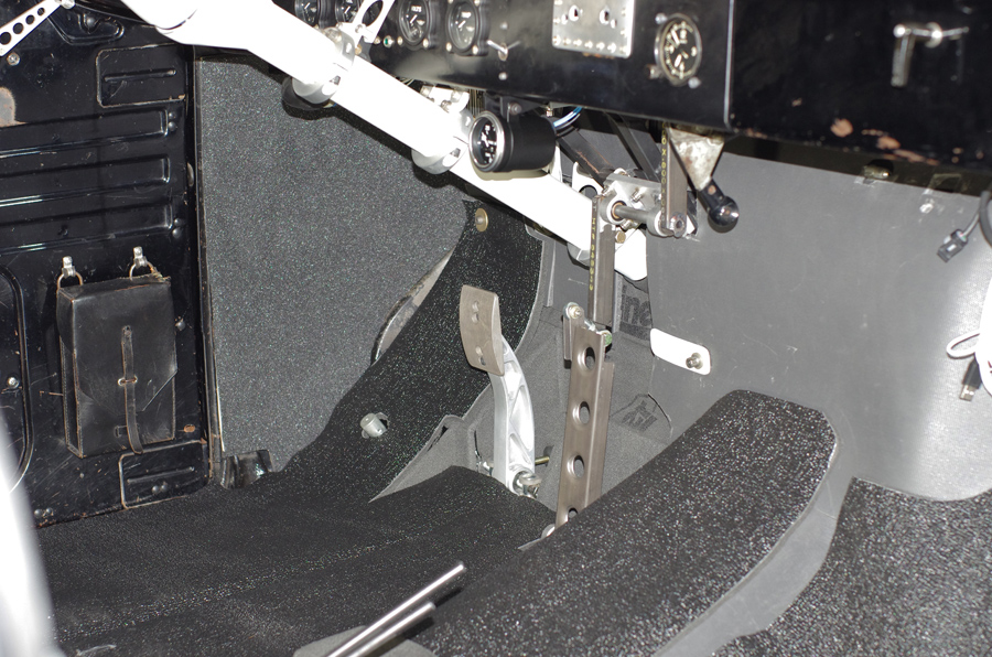
Here's a shot of the new Tilton brake pedal as well as the throttle pedal I fabricated. You can also see the transmission temperature gauge that I added below the dash. I figured after all this trouble I should able to keep an eye on what's going on down there:
Here is the trans temp sensor installed in the B&M pan:
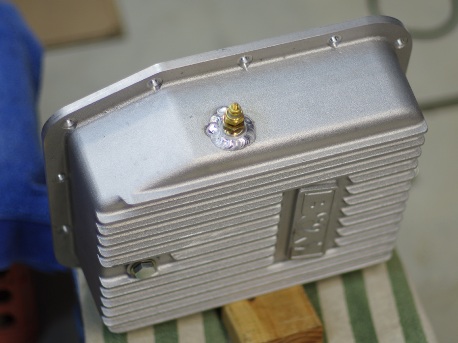
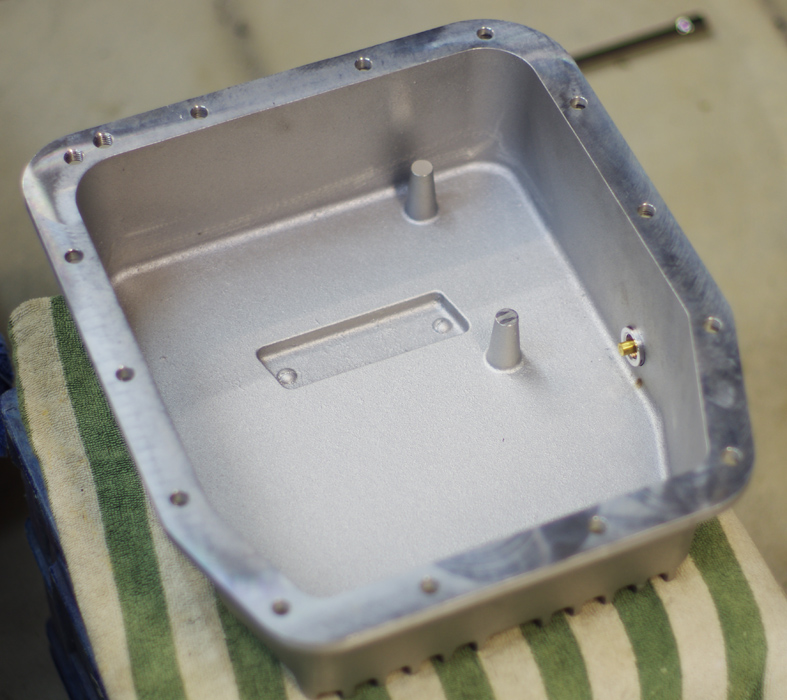
I wimped out on welding the bung, and had a local engine machine shop do it. I figured this might not be the best place to learn how to TIG aluminum.
Gustave
11-20-2015 #58
Registered User
- Join Date
- Dec 2010
- Posts
- 709
This is great stuff--thanks for taking the time to spell it out!
12-08-2015 #59
Starting The Transformation
- Join Date
- Feb 2010
- Location
- El Segundo, CA
- Posts
- 268
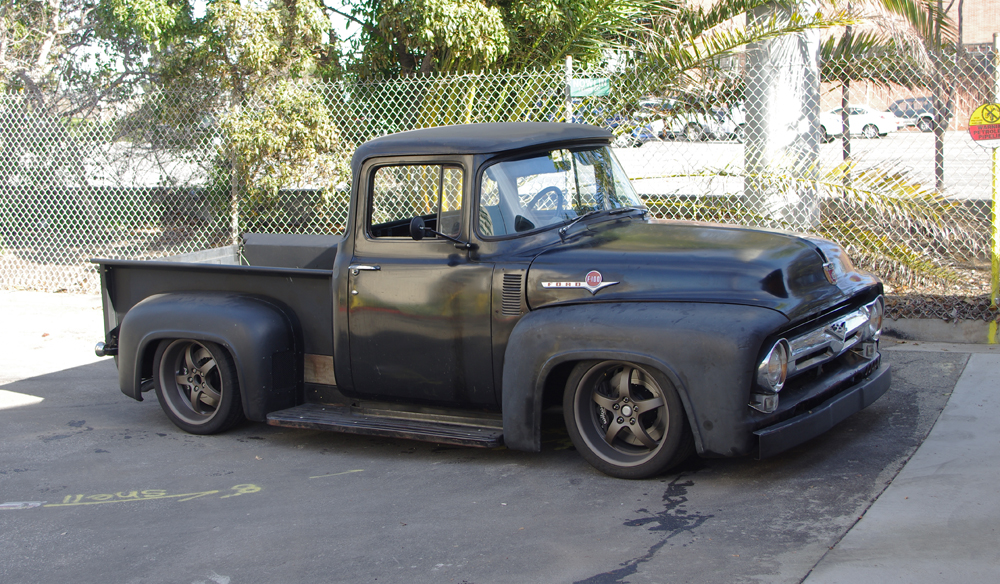
Got the truck back on the ground. Went for a shake-down drive today to bed in the brakes. Took a quick photo when I got back. It's sitting too low right now. I'll need to swap out the front springs to longer ones to get it where I want it. It drives just great, but the tires contact the fender lips during tight maneuvers.
The work to the suspension had the desired effect of making the truck much more comfortable to drive on the street. No more bashing over bumps and ripples. Also, the 12 deg of caster is surprisingly benign. I thought it might feel extreme, but I hardly notice it, other than better straight-line stability.
I'll take more pics soon.
12-08-2015 #60
Registered User
- Join Date
- Feb 2005
- Location
- Minneapolis, MN
- Posts
- 195
Looks mean!

 Reply With Quote