
Results 1 to 20 of 38
-
07-28-2013 #1
 Registered User
- Join Date
- Jul 2013
- Posts
- 14

HELP, how do I set my 3 link bars?
I've decided to build a 3 link with a chassis mounted watts link, my problem is I can't find any solid info on how to set my lower and upper bars. The hole idea is to make it a one and done kinda deal. It'll see a lot of street time and a few passes here and there at the strip and 6-8 autox events.
Here's a pic from my previous post
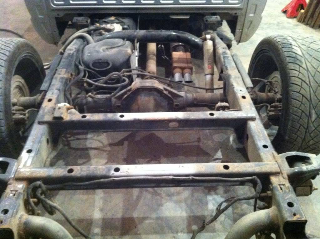
Any suggestions or help is appreciated!
-
07-28-2013 #2
Registered User
- Join Date
- Nov 2012
- Location
- Sacramento, CA
- Posts
- 1,918
More info please ...
1. What kind of car is it?
2. Are you buying a kit ... or buying brackets, tubes & rod ends to build your own?
3. What kind of space & frame do you have to work with?
* Posting some photos will help us to guide you.
.
07-28-2013 #3
Registered User
- Join Date
- Jul 2013
- Posts
- 14
I edited the post and added a pic. Originally Posted by Ron Sutton

Yes I will be buying the brackets, tubes, and rod ends to build my own. The fuel thank that's in it now will no longer be in it after tomorrow. I've heard that my top link should be shorter than my lowers, is that true as well?
07-28-2013 #4 Registered User
- Join Date
- Dec 2010
- Location
- Chino Hills
- Posts
- 32
The easy way is to set them so they angle up slightly toward a magical place about a 18 inches in front of you bumper. This give the best IC from what I read.
Or the way I set a parallel 4 link was too have the rear pivots 1.5 inches lower then the front. Although 1-2 inches is ideal from a getting it stand point. Or to have a perfect set-up one needs to have alot of basic info to properly set it up to ideal standards.Sitzungstiefpunkt und fahrend langsam
07-29-2013 #5
Registered User
- Join Date
- Nov 2012
- Location
- Sacramento, CA
- Posts
- 1,918
The most tunable & best suspensions for many applications are the 3-link & 4-link.
Basics:
The 3-link has two lower links often called lower trailing arms or lower control arms and one upper link often called the top link, 3rd link or upper control arm. The top link can be centered, offset or angled. The reason to offset or angle the top link is to counteract the torque transmitting through the rear end housing.
The 4-link has two upper & two lower links. For racing & track applications the triangulated 4-link is not optimum, as you dont want any forces pushing or pulling in a direction other than parallel. So were only discussing parallel 4-links here.
The design, set-up & tuning concepts are the same for both 3 & 4 link rear suspensions. The 3-link allows for more rear end housing articulation within the chassis. Both 3 & 4 link rear suspensions will bind at some angle different than the chassis but the 4-link will bind at a lower angle.
For drag racing high power, high rpm, side step the clutch launches the 4-link is better suited to deal with the launch forces. While the bottom links push on launch the top link(s) pull. Pulling the rod ends is more susceptible to failure than pushing. Two links with four rod ends are obviously twice as capable of handling this shock that can be so powerful, the 4-link suspension is lifting the front of the car off the ground.
So, either 3 & 4 link rear suspensions can be used for corner handling & drag racing, but the 3-link has a slight edge for cornering & the 4-link a slight edge for drag racing.
--------------------------------------------------------------------------
Ill outline a step-by-step method for the average car guy to build & install either system. This will be an adjustable system that can be tuned for optimum performance.
Start with the lower links when laying out either system. You want to position them as wide in the chassis as you can (top view), while still providing adequate clearance for tires, frame, etc. Wider placement gives the 3 or 4-link more control over the rear end housing narrower is less. You can mount the front of the lower links under the frame rails, provided you can achieve the correct height for the front rod ends & enough length in the overall lower link to minimize angle changes as the suspension travels.
There is no magic number, but I like to see the center-to-center distance on the lower links be 24 to 36 long. If you cant fit the bracket you want under the frame rail, then youll typically mount the front brackets inside the frame rails. You need to space the brackets far enough away from the frame rail to put a nut on the bolt.
Lets talk height of the front & rear mounting points for the lower links. Again, no magic number here. But youll want to understand the concept of roll steer or rear steer which have the same meaning. The lower links control rear steer. If the lower links are perfectly horizontal level with the ground when the car is at ride height the car will not have any rear steer effect as long as the rear of the car rolls evenly.
Rear Steer:
If you adjust either end of the lower links and end up with the pivot points higher in the front (towards the cockpit) the car will now have a rear steering effect as the chassis/body rolls. The link on the outside of the corner pushes the rear end housing back while the link on the inside of the corner pulls the rear end housing forward, making the rear of the car provide a steering effect, helping the cars ability to turn. This frees up the car throughout the corner, as long as chassis/body roll exists, including while trying to power out of the corner, which can make the car loose on corner exit.
If you adjust either end of the lower links and end up with the pivot points lower in the front (towards the cockpit) the car will now have a counter rear steering effect as the chassis/body rolls. The link on the outside of the corner pulls the rear end housing forward while the link on the inside of the corner pushes the rear end housing back, making the rear of the car provide a counter steering effect, hurting the cars ability to turn. This tightens up the car throughout the corner, as long as chassis/body roll exists, including while trying to power out of the corner, which can make the car exit better with more grip unless it is too much, then it can push on corner exit.
I strongly suggest you design yours for level lower links and have holes or slots for adjustment each direction for tuning. Rear steer can be a good tuning tool once you learn how to use it.
Its easiest starting at the housing. Youre either going to buy or make brackets that weld on the rear axle housing tubes. Most tubes are 3 OD but measure yours to be sure. There is no magic height number everyone should run. But remember, if your lower links are level as you extend the imaginary line forward to intersect with the top link(s) the height of the lower links is going to be the height of your intersect point known as the Instant Center or IC.
If youre buying brackets, most are going to have holes or slots ranging from 4 to 7 below axle Centerline (CL). In my experience that is a pretty good range. My only rule of thumb here is higher points help me get the IC we need for lower powered cars & lower points help me get the IC we need for higher powered cars.
To get an idea of where your lower link rear pivot point will end up or points if you have multiple holes requires doing simple math. Tire height divided by two minus expected tire sag from load tells us about where the axle CL should be. Example: 26-1/2 tall tire divided by two = 13-1/4 minus ¼ expected tire sag for stiff sidewall, low profile tires on wide rims with 35+psi puts the rear axle CL at about 13.
If you bought axle brackets with 3 holes, one inch apart, at 4-1/2, 5-1/2 & 6-1/2 from axle CL that would put your lower link mounting holes at:
Top: 8-1/2 above ground
Middle: 7-1/2 above ground
Bottom: 6-1/2 above ground
* For PT cars with 500+hp, Id start in the bottom hole.
Now, you need to place the front mounts (for the lower links) so you can achieve level links and holes slightly up & slightly down. You need to find brackets to fit your application with modification of course that will allow you the mounting points you want. Dont get lazy here. Cut, trim or modify them as needed to get the proper mounting points.
Tip: On one end of the lower links either at the housing or frame I like to have a slotted mount to fine tune the lower link angle. Because sure as the sun rises, when you have your car finally done and sitting on the ground at ride height, with driver weight in it
a. It is easy for one side to be different than the other, if the car is not weight balanced side-to-side.
b. They will probably end up close but not spot on zero.
If you have only holes for adjustment a single hole change can be 1.5 to 2.5 degrees. But if you have slots, you can adjust the driver side that sagged to 0.6 down with your fat butt in it back up to 0.0. And adjust the other side, that ended up 0.3 up back down to 0.0. Now the rear end of the car will NOT be contributing to different handling effects on LH & RH corners.
Make sense?
P.S. The lower links are compressed under launch & acceleration on corner exits so the slot is not at risk of being ripped out. Do NOT put slots on the upper links, as they pull and over time will cause failure if slotted.
P.P.S. If I have a bracket I like, that fits the application and it only comes with holes (no slots) I simply connect two holes & make a slot. I do this in a mill. If you do this by hand, sneak up on it, as you dont want that rod end bolt loose in the bracket.
When you go to place the front brackets for the lower links, be sure:
a. The links are going to be level at ride height when viewed from the side.
b. The links are truly parallel with the car/chassis when viewed from the top.
c. And the rear end is absolutely centered in the car/chassis, level with the chassis & square to the chassis.
Now is a good time to pre-set your pinion angle before you weld on the housing brackets.
d. Make sure the pinion of the rear end truly lines up with your driveshaft & transmission (top view) so the driveshaft is not running at a side angle.
e. Find a flat surface on the rear end that you believe to equal to the pinion or 90 degrees to the pinion where you can place a digital angle gauge (inclimeter).
f. Measure the driveshaft angle.
g. Roll the housing to place the pinion at a 2-3° downward ANGLE DIFFERENCE from the driveshaft.
* This is NOT a 2-3° angle from the ground, unless the driveshaft runs level with the ground. If the driveshaft runs uphill (uphill going from the rear end to the transmission from a side view) at 4° the you want the pinion going uphill at 1-2° ... to achieve 2-3° downward angle difference.
The purpose of the angle difference is to have the pinion aligned with the driveshaft under hard acceleration loads ... when the pinion rotates up & all the slack or clearances are taken up ... then have a small angle difference when cruising. This 2-3 downward angle difference number is with rod ends. If you run rubber or poly bushings that will allow the housing to rotate more, you will need to start with more angle difference. I suggest a 4° difference and then go test.
We test two ways. One is with a GoPro camera mounted to watch the pinion & driveshaft relationship under different driving conditions. The second is on a chassis dyno, tuning the angle difference for optimum power.
Do not buy into the old school strategy of using pinion angle to increase traction. This binds the pinion bearings.
Make sense?
Bring this up & lets discuss it if is not crystal clear.
--------------------------------------------------------------------------------------------------
When determining your needed lengths for all 3 or 4 links make sure the rod ends have AT LEAST as much threads in the link as the thickness of the rod ends at the links longest possible length. In other words, if youre using ¾ rod ends make sure you have a MINIMUM of ¾ of rod end thread in the links at all times. If not, buy or make new longer links that get more thread inside or put me in your will Im OK either way.
Spell my name R O N just kiddin sorta.
--------------------------------------------------------------------------------------------------
Upper Links:
You need to shop for, or make, your front & rear brackets for the top links at the same time because angles need to be worked out. If youre building a 4-link, you may buy one-piece 4-link brackets that slide over the axle tubes or cut them & weld on in halves and therefore your upper housing brackets are already worked out. If youre doing them separately, youll need to work out how high you want the pivot point holes to be & find or make appropriate brackets.
Note for 4-links: You do not have to place the upper links in line with the lower links (top view). They can be placed wider or narrower to some degree if that helps with packaging. Wider upper links provide more control & less articulation. Narrower upper links provide less control & more articulation.
For 3-links, the upper link can be centered or offset to the passenger side to help counteract torque on acceleration. No one can tell you accurately how far to offset it. The formulas Ive seen involve rear steer, which makes no sense for handling cars. My rule of thumb is 8-12% of track width. Sometimes in the real world packaging challenges play a role.
Upper link angles act the same regardless if the car is a 3 or 4 link. Obviously, you want both upper links of a 4-link to be on the same angles. A quick car guy guideline is youll end up with the upper link(s) anywhere from level to pointing downward in the front 15 degrees. Thats about the max range youll ever use. If you can build your rear housing mount(s) & front mount(s) with enough holes to achieve those two angle extremes youll be good. If you have to have less range I suggest a window of 3 to 8 degrees.
The upper link angles are the final determining factor of your rear suspensions Instant Center location. Remember youre lower links are level. So if you have any downward angle in your upper link(s) the imaginary projection lines of each set of links will intersect at the height of the lower links somewhere forward of the axle. How far is dependent on the height & angle of your upper link(s).
Lets talk Anti-Squat. If you run the upper links exactly level & perfectly parallel with the lower links there is no intersect point no instant center and is considered zero Anti-squat. This will provide the most secure corner entry under braking because the rear suspension of the car is not contributing to the pitch angle under braking. But it will provide the least grip to the rear tires on corner exit because the rear suspension of the car is not contributing any leverage helping to load the rear tires.
If you adjust the upper link(s) at either end placing the upper link(s) angling downward in the front there will be an intersect point with the lower links imaginary line creating an instant center somewhere forward of the rear axle and the rear suspension is considered to now have some percentage of Anti-Squat. The steeper the angle downward in front the more Anti-squat the suspension has and will mechanically contribute to the pitch angle of the car under braking making the rear of the car lift more. But it will provide more grip to the rear tires on corner exit because the rear suspension of the car will now contribute leverage helping to load the rear tires.
If you go too far with the goal of gaining more grip for corner exit or hard drag style launches and end up with too high of an Anti-squat percentage you will make the car loose on corner entry under braking. The key is finding the right balance for your car & goals and tuning it to achieve optimum set-ups for different types of driving if you become a serious competitor.
If you want to play around with different combinations, you should buy Performance Trends 4-link plus software. It works just as well with 3 links. See it HERE.
Only as a guideline, a good starting point for many performance cars is starting with the upper link(s) pointing downward in the front with a 7 degree angle. This should put you around 40% Anti-squat which is a good balance for corner exit grip without making the car too loose on entry. There are tricks to run more angle, but I cant outline them here.
If you start here, and the car is a little too loose on corner entry & you have everything else in the cars suspension good you can just take some angle out of the upper link(s). If it is not affecting your corner entry under braking, you may put more angle in the upper link(s) and watch your corner exit grip increase. When you get too greedy the car will tell you on corner entry buy getting loose.
Upper link lengths:
Some think the upper link(s) is/are supposed to be shorter than the lower links. Thats not accurate. They often end up shorter, due to space challenges underneath many cars. But thats not the goal. The biggest effect the length of the upper link(s) has/have is on pinion angle change during rear suspension travel. If the upper links are shorter than the lower links the pinion angle changes more during suspension travel. The bigger the difference in lengths the bigger the pinion angle change.
I prefer to make the upper link(s) the same length as the lower links space permitting. I have even used upper mounts on the housing that have the holes significantly (1-3) behind the axle centerline to achieve this. If I cant make the upper links the same length, I get them as close to the lower link length (say that 3 times real fast) as I can simply to minimize pinion angle change during suspension travel.
Upper link mounting hole heights:
Again, no magic number. But the farther apart think distance not angle I have the top links from lower links the more control the suspension has & the finer the tuning adjustments. Mounting them closer together makes the tuning adjustments coarser. I have mounted upper links 3 above the axle tubes (so 4-1/2 above axle CL) at the lowest to 5 above the top of the housing with centered 3-links (about 13 above axle CL). If Im running regular tube upper links, I prefer to be somewhere in the middle of that 6-10 above axle CL. But space considerations often play a role.
Clear?
If not digest this for a bit and then lets talk.
.Last edited by Ron Sutton; 08-02-2013 at 05:47 AM.
07-29-2013 #6 Registered User
- Join Date
- Mar 2010
- Posts
- 469
R O N. Congratulations on the most detailed and intense reply to a post in the Trucks section to date. I'll be back later to read it all. Wow.
07-29-2013 #7
Registered User
- Join Date
- Nov 2012
- Location
- Sacramento, CA
- Posts
- 1,918
You know what they say .. if you're going to do it ... Originally Posted by bovey
.
07-29-2013 #8 Registered User
- Join Date
- Apr 2009
- Location
- san diego
- Posts
- 5,102
Ron nice right up. How do you find the time to make these great posts. I try to get about 30 minutes a day to read all the cool stuff in these forums and find little time to post.
My build thread: https://www.pro-touring.com/showthre...ing&highlight=
The mustang build thread: https://www.pro-touring.com/showthre...el)&highlight=
07-29-2013 #9
Registered User
- Join Date
- Nov 2012
- Location
- Sacramento, CA
- Posts
- 1,918
Originally Posted by Bryce
I'm writing a series of tuning books right now ... and the forums give me a platform to try out the wording.
I need to make sure "car guys" can understand it without questions ... because it's hard to ask a book questions.
.
07-30-2013 #10
Registered User
- Join Date
- Oct 2012
- Posts
- 434
When you need a proofreader for your books, I'll send you my address
07-30-2013 #11
Registered User
- Join Date
- Nov 2012
- Location
- Sacramento, CA
- Posts
- 1,918
Originally Posted by mitch_04
Hi Mitch,
Is that what you do? ... are you just funning me ?
.Last edited by Ron Sutton; 07-30-2013 at 01:49 PM.
07-31-2013 #12
Registered User
- Join Date
- Oct 2012
- Posts
- 434
Well....I read a lot of automotive books
I've seen too many books that are out and about with terrible grammar errors and the common problem of jumping around from topic to topic without any useful bridging. Also a huge problem, stating their opinion as fact. I understand some book writers have tons of valuable experience (obviously you would fall in this catagory) but that doesn't mean they can't precede their opinion with a simple "this is my opinion, not a set in stone truth" kind of statement. Sometimes theory can not or has not been proven yet, but that doesn't mean it should be excluded entirely either. I read David Vizards book on cylinder heads and, although he has an amazing amount of experience, he seemed like he was trying to prove himself the entire book. He had some great ideas, but there was so many things that should have been left out of that book. Overall I would never recommend that book to anyone. That doesn't mean I didn't learn anything, but it was just so few and far between that it didn't justify recommending. The book hardly touched on the actual act of porting, which is what most people are buying for. The theory and reasoning behind the porting was very well covered.
Also, a common problem is throwing out terms assuming people know them. Have a simply explanation on the sidebar, or a reference the glossary.
07-31-2013 #13
Registered User
- Join Date
- Nov 2012
- Location
- Sacramento, CA
- Posts
- 1,918
Awesome. When I get to a final rough draft, I'll contact you.
07-31-2013 #14
Registered User
- Join Date
- Oct 2012
- Posts
- 434
Amazing! Don't worry, I'll pay you for the copy, but I expect a signed one
Don't forget us little people when you are rubbing elbows with Stephen King and the like...
08-01-2013 #15
Registered User
- Join Date
- Jul 2013
- Posts
- 14
Well I can understand it, I've probably read it like 5 times. Where would you suggest getting all my brackets? After that article I've changed once again to a four link Originally Posted by Ron Sutton
08-02-2013 #16
Registered User
- Join Date
- Nov 2012
- Location
- Sacramento, CA
- Posts
- 1,918
Did you get clear on the pros & cons of 3-links & 4-links? I don't think we covered it. Originally Posted by BoostedSport
Regardless, I don't want to steer you from a 3-link towards a 4-link. If anything, it would be the other way around.
Last edited by Ron Sutton; 08-02-2013 at 06:09 AM.
08-02-2013 #17
Registered User
- Join Date
- Nov 2012
- Location
- Sacramento, CA
- Posts
- 1,918
Oh you are funny. Originally Posted by mitch_04
08-02-2013 #18
Registered User
- Join Date
- Nov 2012
- Location
- Sacramento, CA
- Posts
- 1,918
Hey Guys,
I'm going riding quads with my girls now ... so I'll catch up with everyone when I get back Monday.
Take care all !!!
08-04-2013 #19 Registered User
- Join Date
- Dec 2006
- Location
- Out of the Burbs of Detroit to SoCal, then onto my ancestral homeland, the woods of Cascadia
- Posts
- 1,753
Ron-
Thanks for the explanation of setting link angles, etc. Been trying to find out the design rationale for a 3 link for a while- never seen an explanation as succinct as yours on design of 3 and 4 links- and I've been to Shoppes web page.
Tell us a little about the book, and if the content is similar to this, put me down for an advance order.
I want to understand WHY I'm doing something, rather than just buying a pile of parts.Greg Fast
(yes, the last name is spelled correctly)
1970 Camaro RS Clone
1984 el Camino
1973 MGB vintage E/Prod race car
(Soon to be an SCCA H/Prod limited prep)
08-09-2013 #20
Registered User
- Join Date
- Nov 2012
- Location
- Sacramento, CA
- Posts
- 1,918
I agree. And there are a lot of car guys this way ... and there are a lot of car guys that want to buy quality with the engineering already in it ... and simply "bolt-on" performance without having to fabricate or build from scratch, nor learn all this tuning & geometry stuff. I like the diversity & think there is a place for all of us. Originally Posted by Twentyover
These days, with the quality designed & manufactured products from DSE, Speedtech, ridetech, Maier & several others ... you can buy & install amazing stuff. I see great parts, kits & complete assemblies that tremendously improve the performance of cars from the 50's-80's. It is awesome. Not only do cars with these parts & kits perform well on the street, they can be somewhat competitive at track days & AutoX. The bolt on car guys are not going to beat the "Thinker & Tuner" car guys in competition on any regular basis. But it's fun for all of us to do this our own way. I love that about hot rodding in general.Last edited by Ron Sutton; 08-14-2013 at 03:22 PM.

 Reply With Quote


