Results 1 to 20 of 51
-
11-29-2017 #1

 Registered User
- Join Date
- May 2017
- Posts
- 43
Project "ANVIL" F100. Built to be beat on
Hey all
I’m pretty virgin (be gentle) to this whole Pro-touring / handling thing so this Is a learning curve for me.
Quick back story on the toy, I bought this truck 5-6 years ago from the original owner with the sole intention to just drive the wheels off of it. it’s a 1967 Ford F100, short bed, 240 6 cylinder, 3 on the tree. I did start driving it and honestly loved it. tons of complements everywhere I went. One morning I went out to leave for work and the truck was in the middle of the street. at this point I knew the engine was done. Virtually zero compression and just plain worn out. So being that I work in the performance world and I like to do things a little different I decided that I need to build a 300 6 cyl…..so I did… block was zero decked, flat tops, ported head, nasty custom ground cam, header with twice pipes and a 600 cfm 4 barrel, and a Frankenstein electronic ignition that I built. I installed the engine, broke in the cam and took her for a test drive. Thing was fun to drive. Skinny little tires just spun their butt off. After the test drive I never touched the truck again. Life was just crazy, 2 athletic boys in high school that did sports year round took my attention from the truck….all good. My boys are my life……………..BUT now that they are graduated and off to college …………….. IT”S MY TURN !!
Here is the NEW plan (with heavy influence from the Hackster built)
THIS IS A VERY BUDGET ORIENTED BUILD. NOTHING CRAZY HIGH END AND 100% DONE BY ME
2009 cop car (p71) Crown Vic front swap, Lincoln Mark VIII IRS rear, coil over’s all 4 corner’s, 3:55 gears and a posi, 2016 Mustang track pak wheels tires, stick with the 6 Cyl for now, T-5 5 speed for better gear split and over drive. Future plans are swapping to an 6.0 LS, Mast head’s, custom cam, Holley Hi-ram, 102mm t-body. 120 injectors, along with an S480 turbo that is in my garage now. I’m looking for a T-56 6 speed but I have a TH400 in the garage and might just go 4L80E……….anyways
*
Here we go
- - - Updated - - -
Can't seem to add pics
-
11-29-2017 #2
Registered User
- Join Date
- Aug 2014
- Posts
- 435

I host mine on Flickr, now after the Photobucket debacle.
Find the picture on your photostream, click on it, then click on the curved arrow when the larger version of the image pops up.
Copy the link and paste it into your post.
Jay
11-30-2017 #3
Registered User
- Join Date
- May 2017
- Posts
- 43
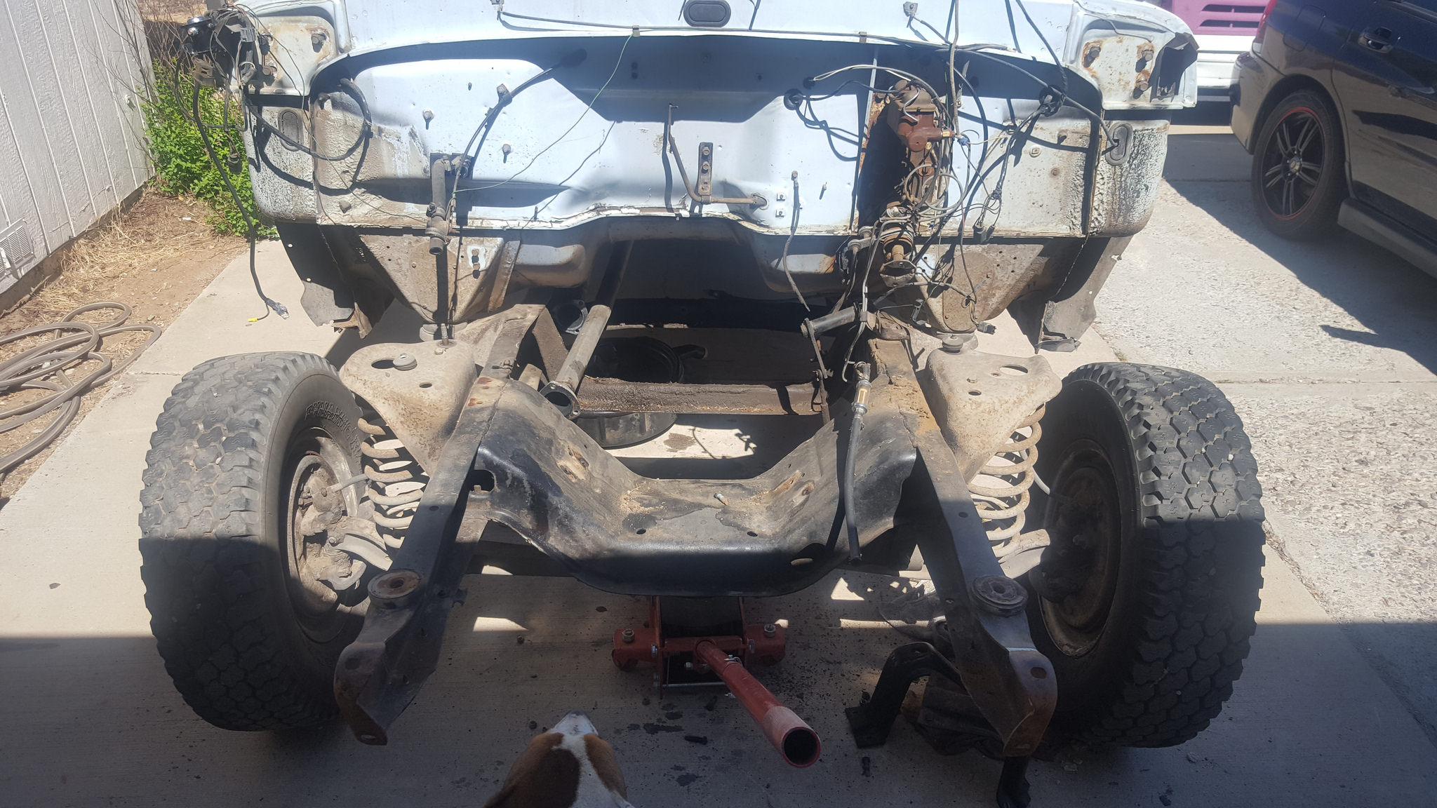
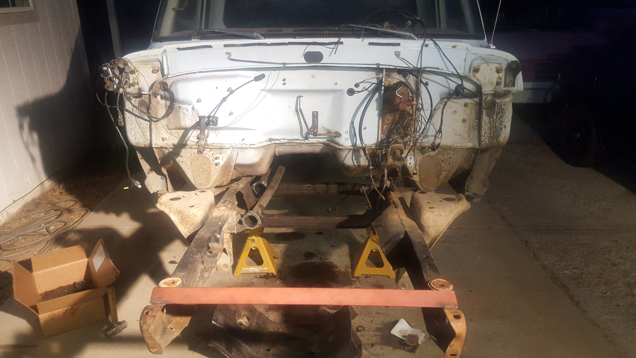
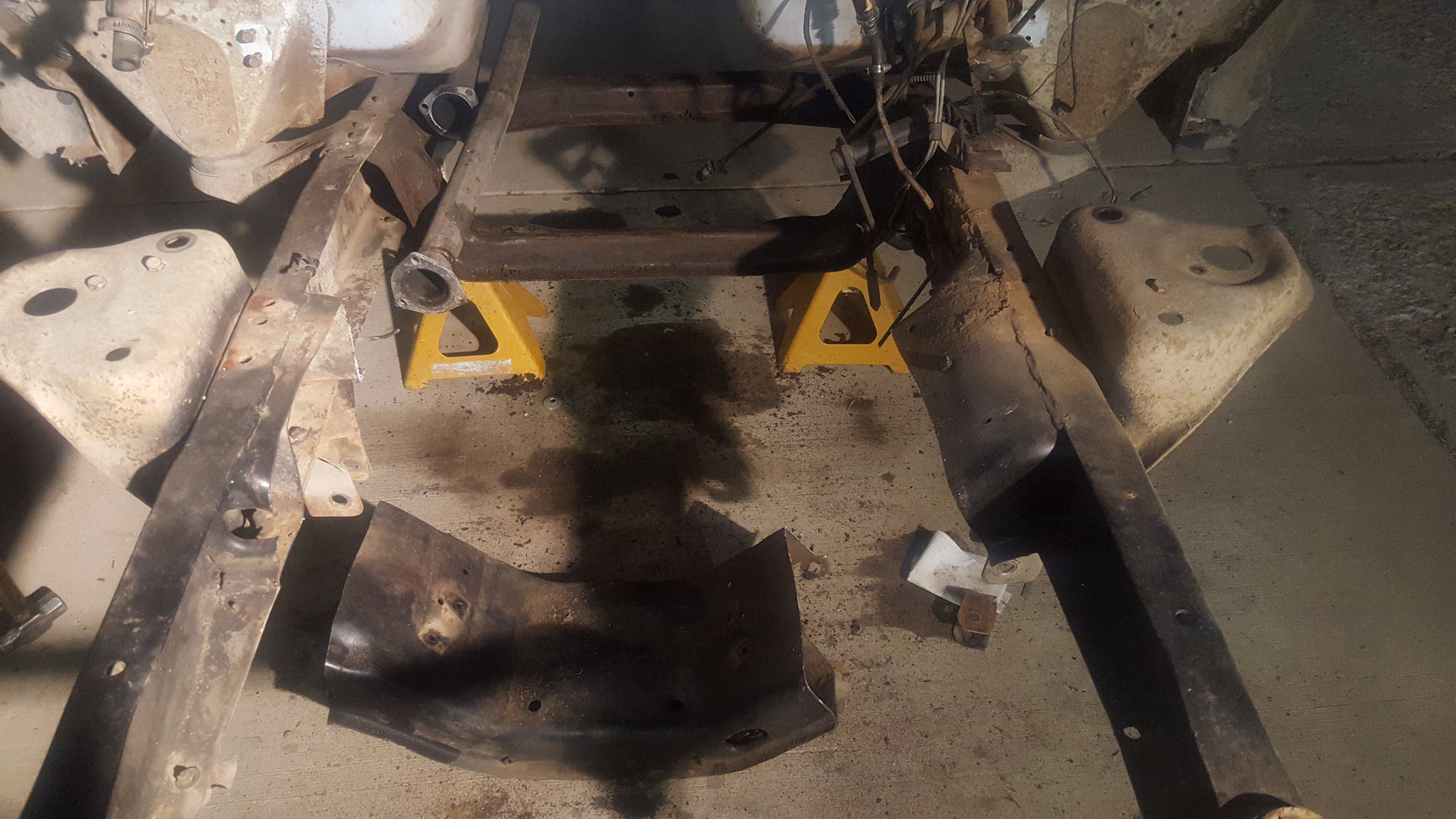
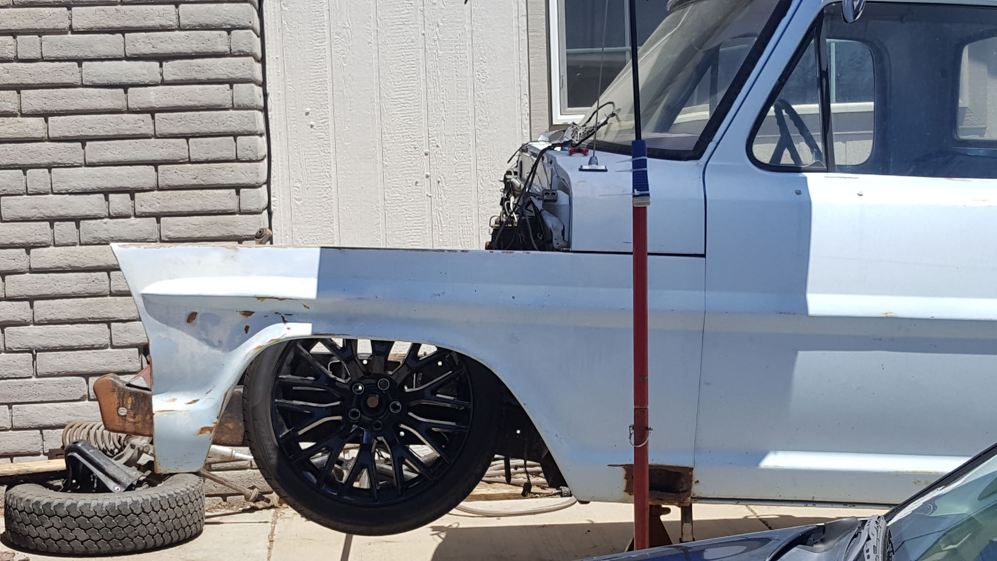
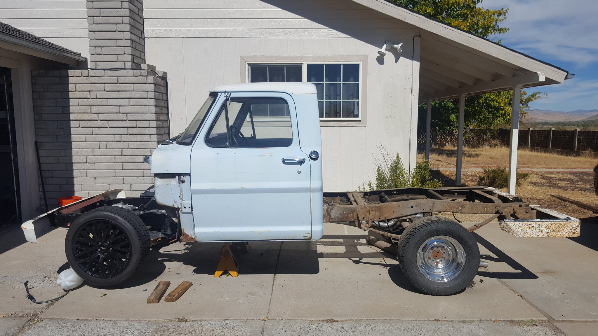
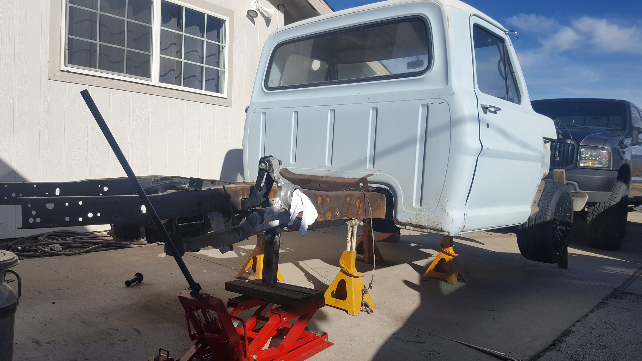
Back in July my Dad came over for a week just to hang out. I took time off of work to hang out with him. All he could talk about was this truck and the CV swap that I wanted to do. I told him hell lets start cutting her up. He was like a kid in at Christmas. The next morning, we started disassembling the sheet metal and leveling the truck on jack stands to get ready to fire up the saw-z-all. I did a ton of reading up on this front long before I even bought the suspension just so I knew what I was in for on the front side.
Since I live in Northern Nevada and at the base of the Sierra’s I want this truck to handle and haul ass. In this area there is plenty to do year round so I want it to be a driver too.
 20170711_154037 by 1SAWB, on Flickr
11-30-2017 #4
Registered User
- Join Date
- May 2017
- Posts
- 43
 20170711_154045 by 1SAWB, on Flickr
 20170711_210135 by 1SAWB, on Flickr
 20170711_210140 by 1SAWB, on Flickr
11-30-2017 #5
Registered User
- Join Date
- May 2017
- Posts
- 43
 20170713_112201 by 1SAWB, on Flickr
11-30-2017 #6
Registered User
- Join Date
- May 2017
- Posts
- 43
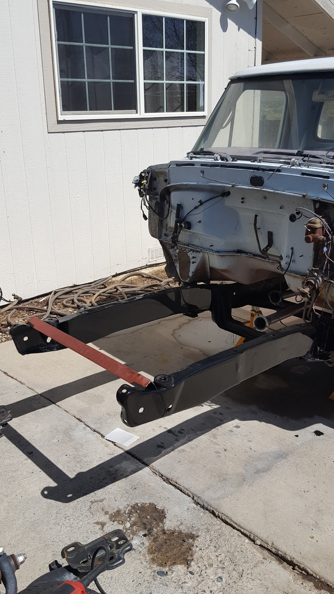
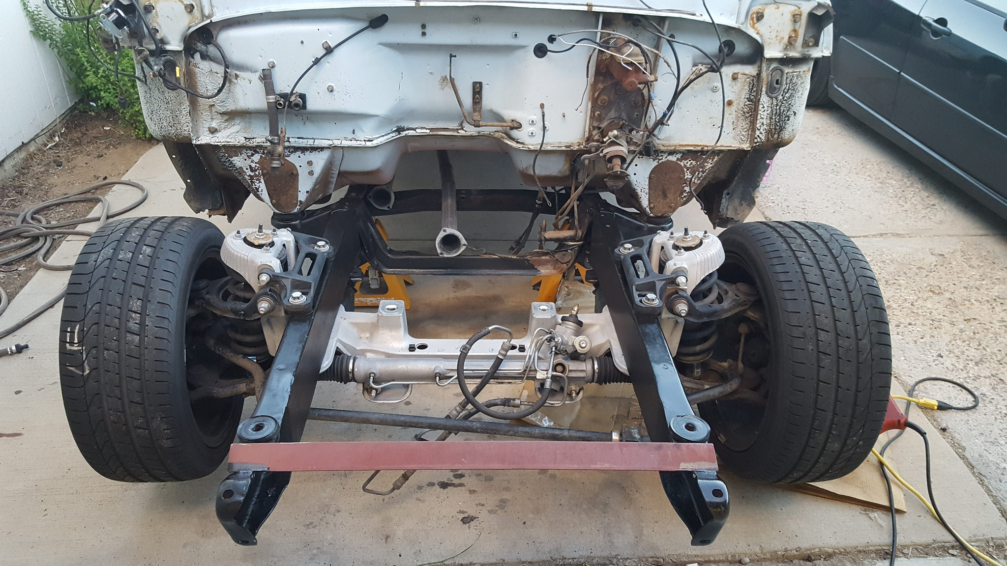
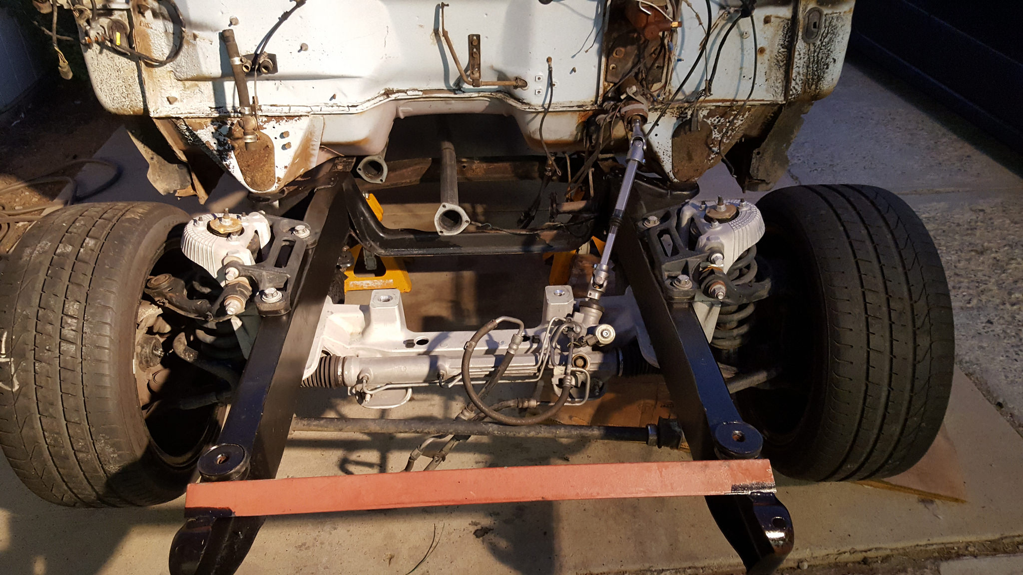
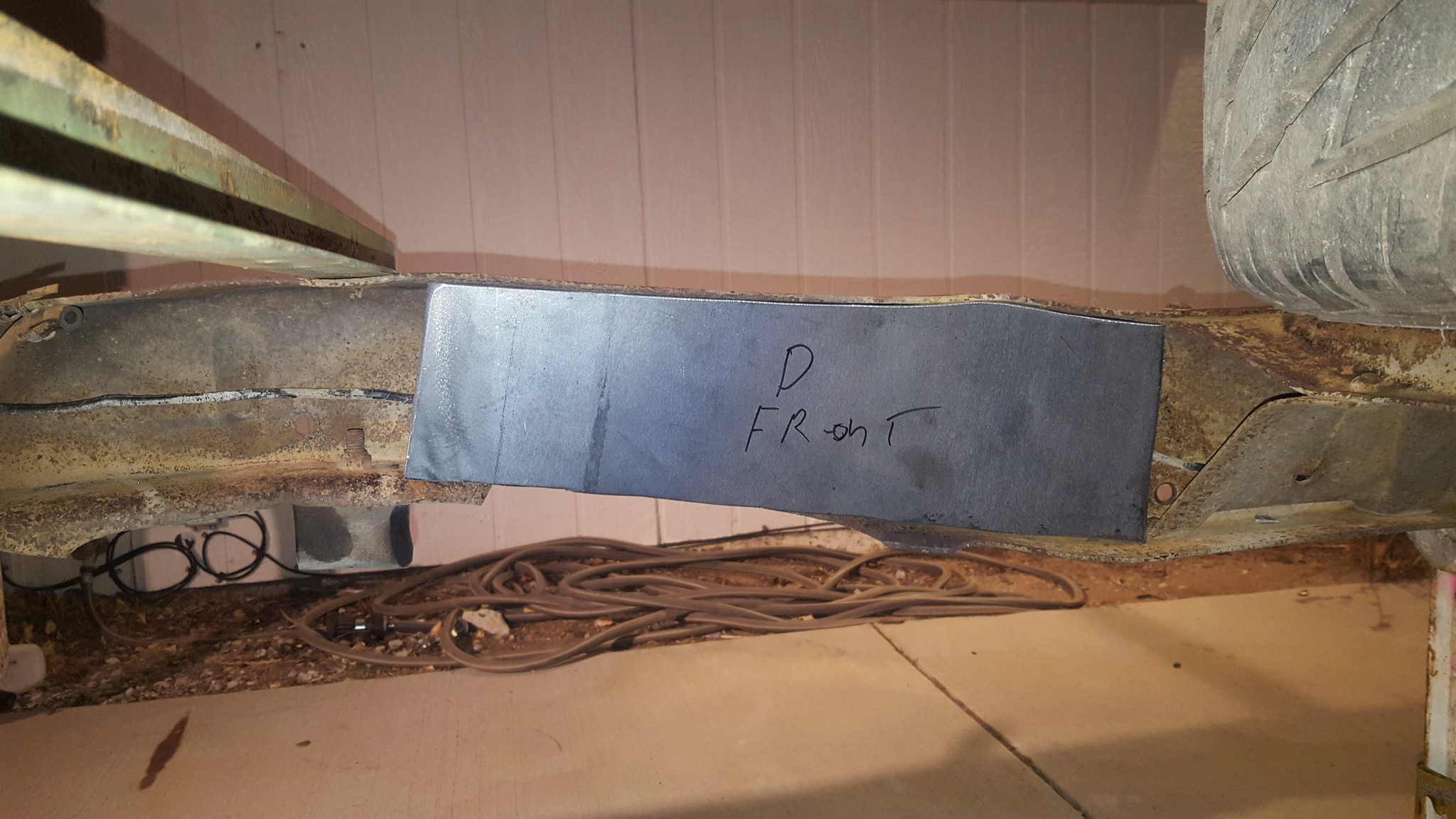
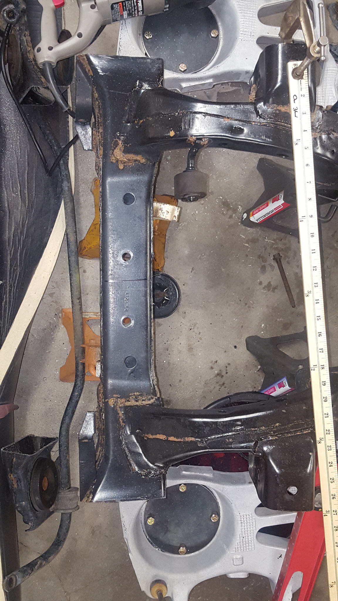
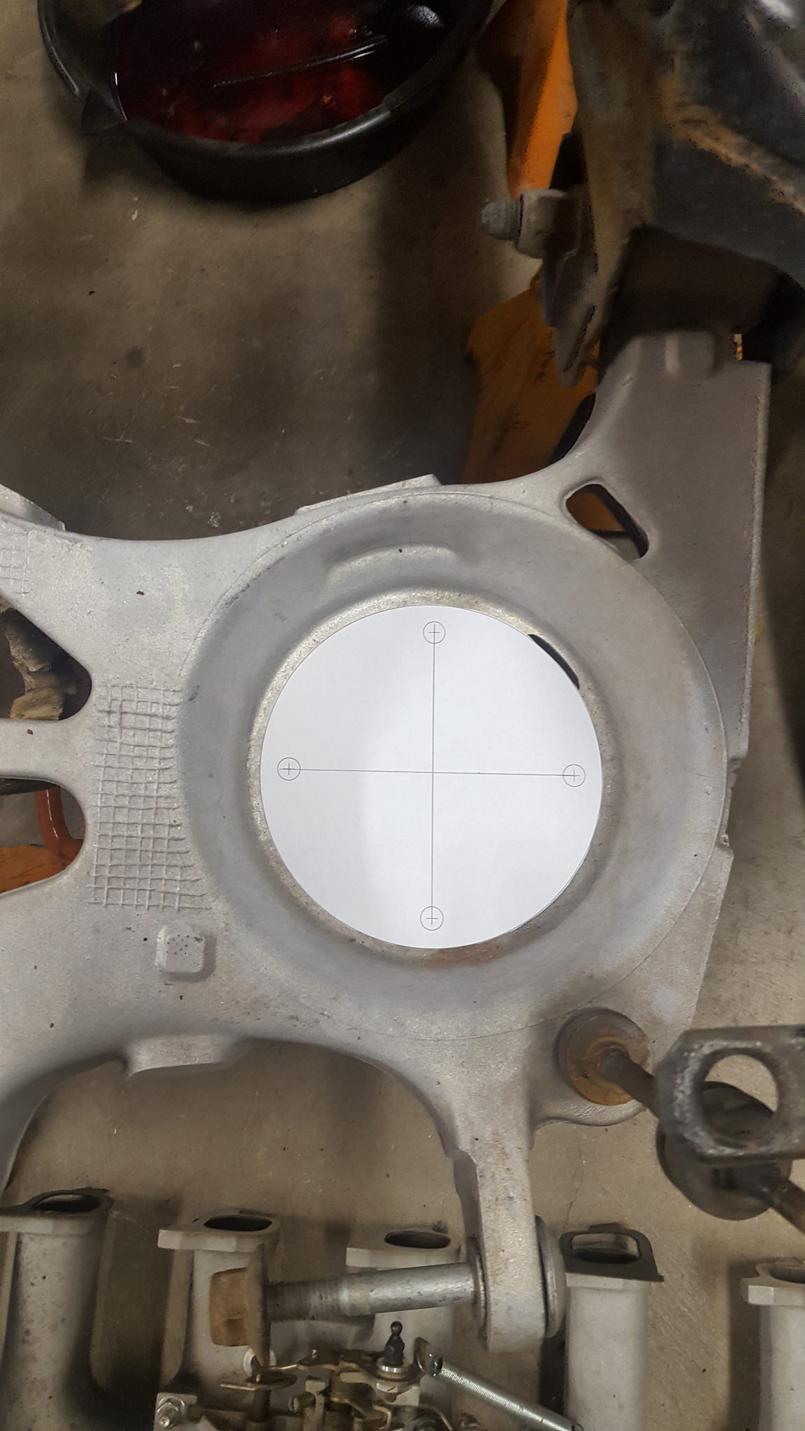
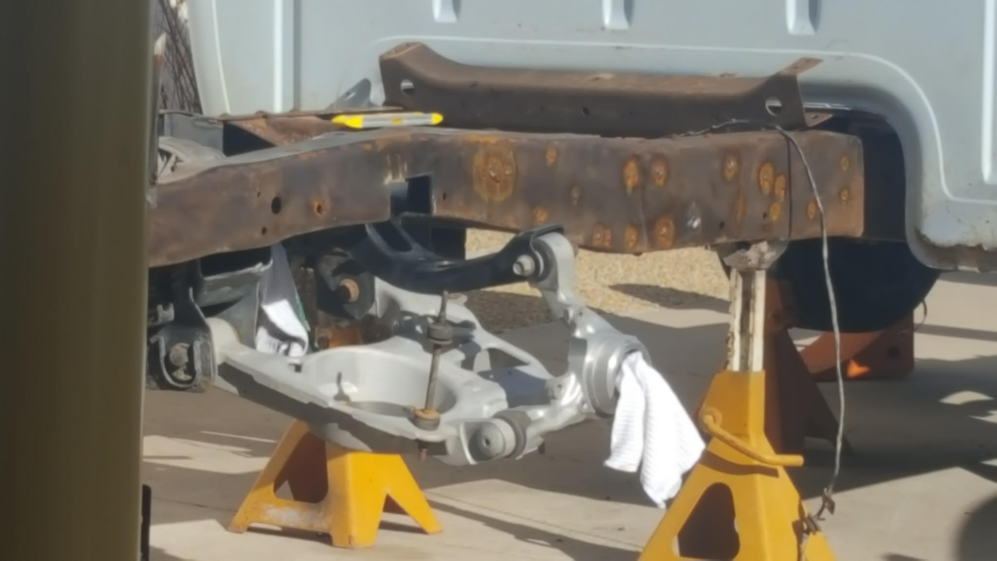
Once the old suspension was all cut out I bolted on a front fender, took a piece of 1" solid I had laying around and put it on top of the frame. slid the wheel on and them centered it in the fender. I then marked the location of the location on the frame. this now gave me the centerline of the wheel. I then transferred this to the bottom side of the frame. on the Crown vic front suspension their is a centering point that is in the suspension cradle that is also the centerline of the wheels. drilled the 3/4 hole, then the four holes to bolt her in, sleeved the inside of the frame for the bolts, and bolted it in to be sure all was well
 20170712_121423 by 1SAWB, on Flickr
11-30-2017 #7
Registered User
- Join Date
- May 2017
- Posts
- 43
11-30-2017 #8
Registered User
- Join Date
- May 2017
- Posts
- 43
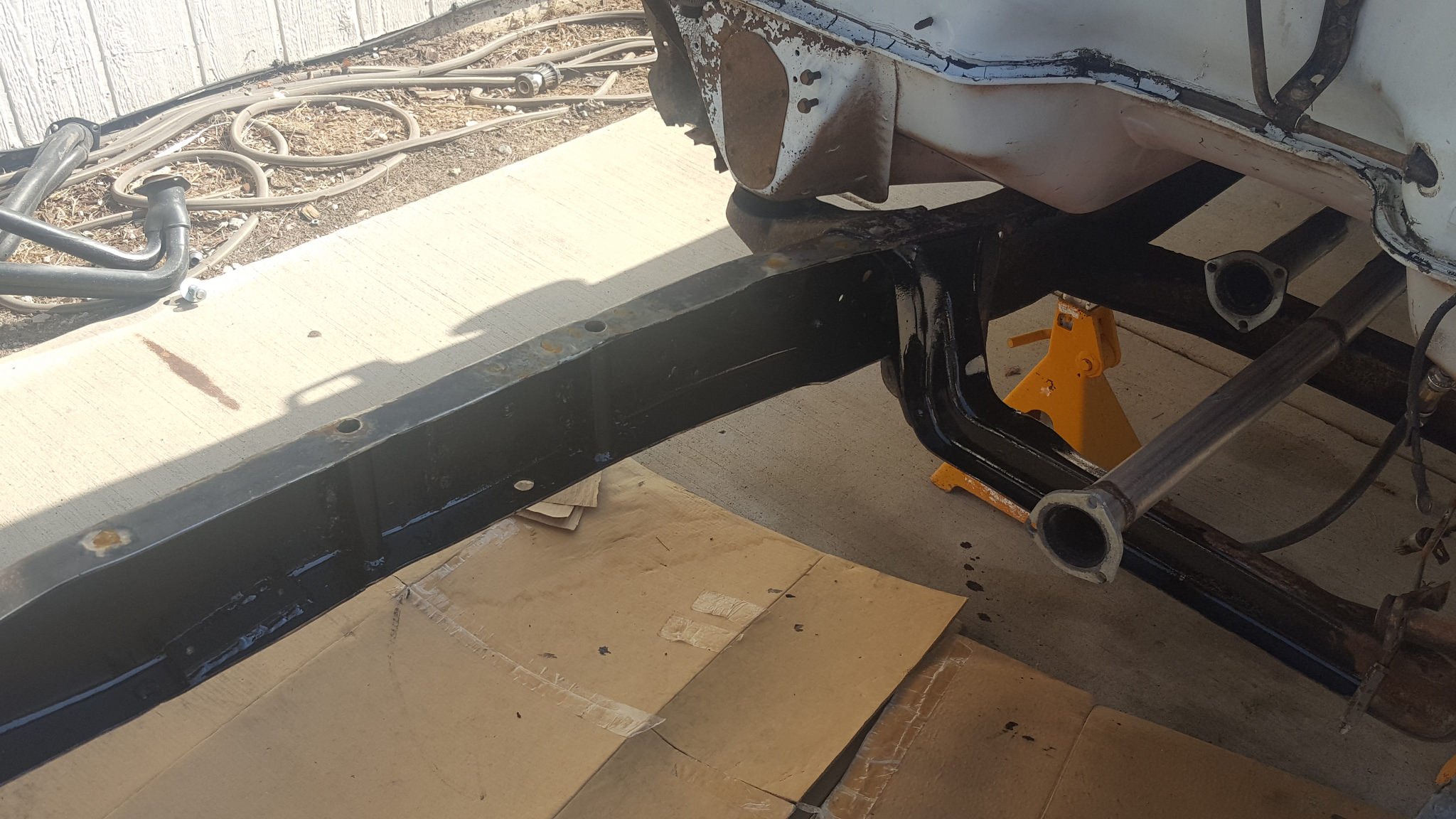
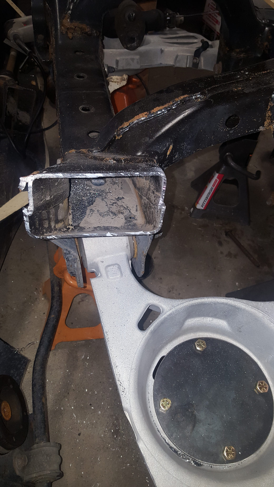
once I was happy with everything I use POR15 inside the frame then boxed it with 3/16
 20170820_094746 by 1SAWB, on Flickr
 20170826_111458 by 1SAWB, on Flickr
11-30-2017 #9
Registered User
- Join Date
- Aug 2004
- Location
- Los Angeles
- Posts
- 592
Cool Build. Where are you located? Looks like there is very little rust, It still has cab mounts!
The rule is measure twice and cut once. My problem is I still measure with a mic and cut with an axe!
11-30-2017 #10
Registered User
- Join Date
- May 2017
- Posts
- 43
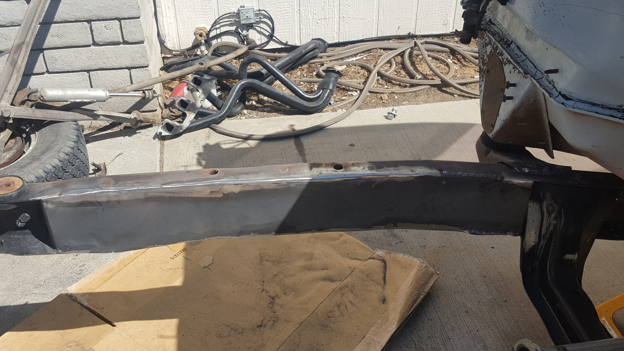
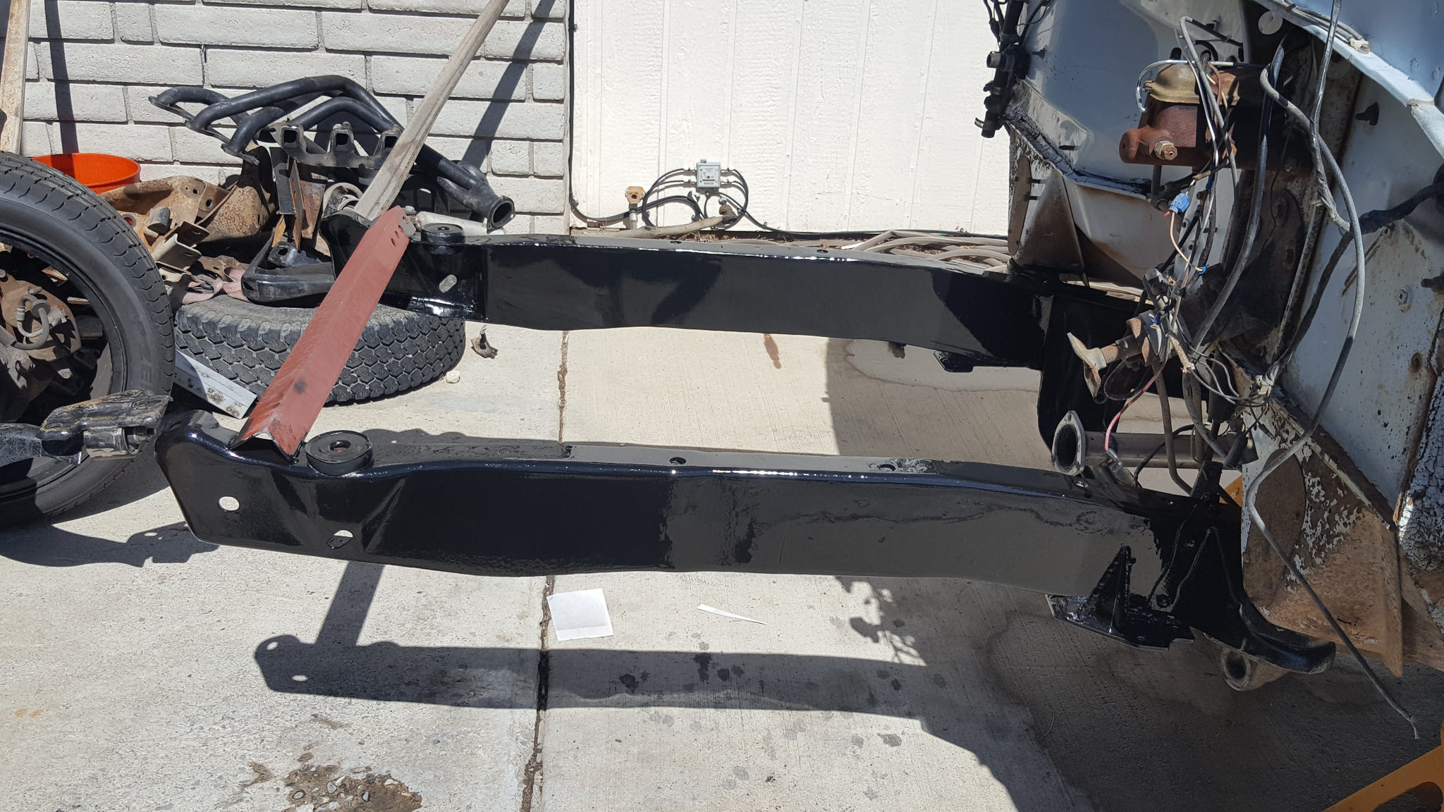
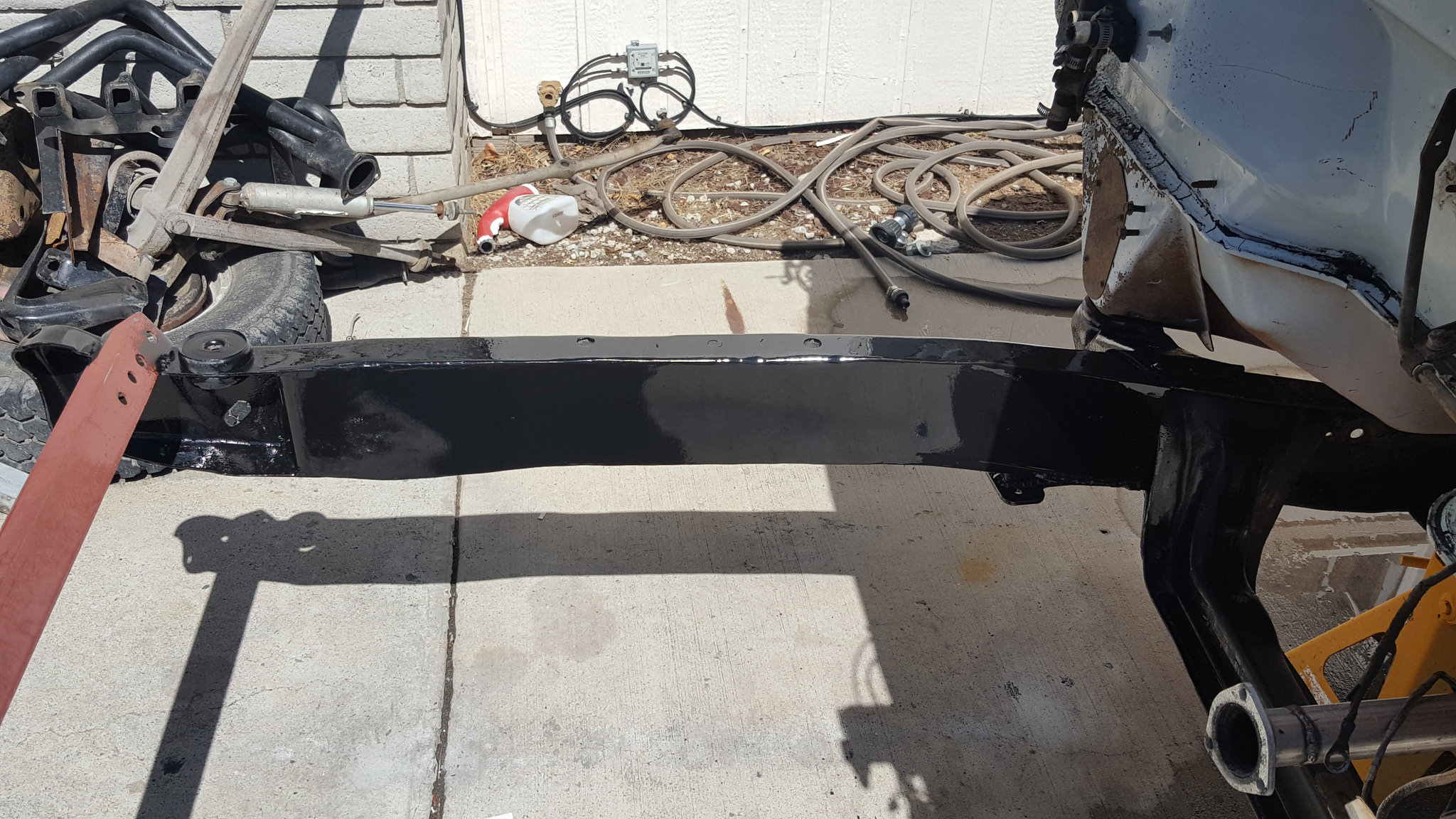
Once the boxing was all welded in I then used POR15 on the outside of the frame too
 20170917_123738 by 1SAWB, on Flickr
 20170917_123746 by 1SAWB, on Flickr
 20170917_123751 by 1SAWB, on Flickr
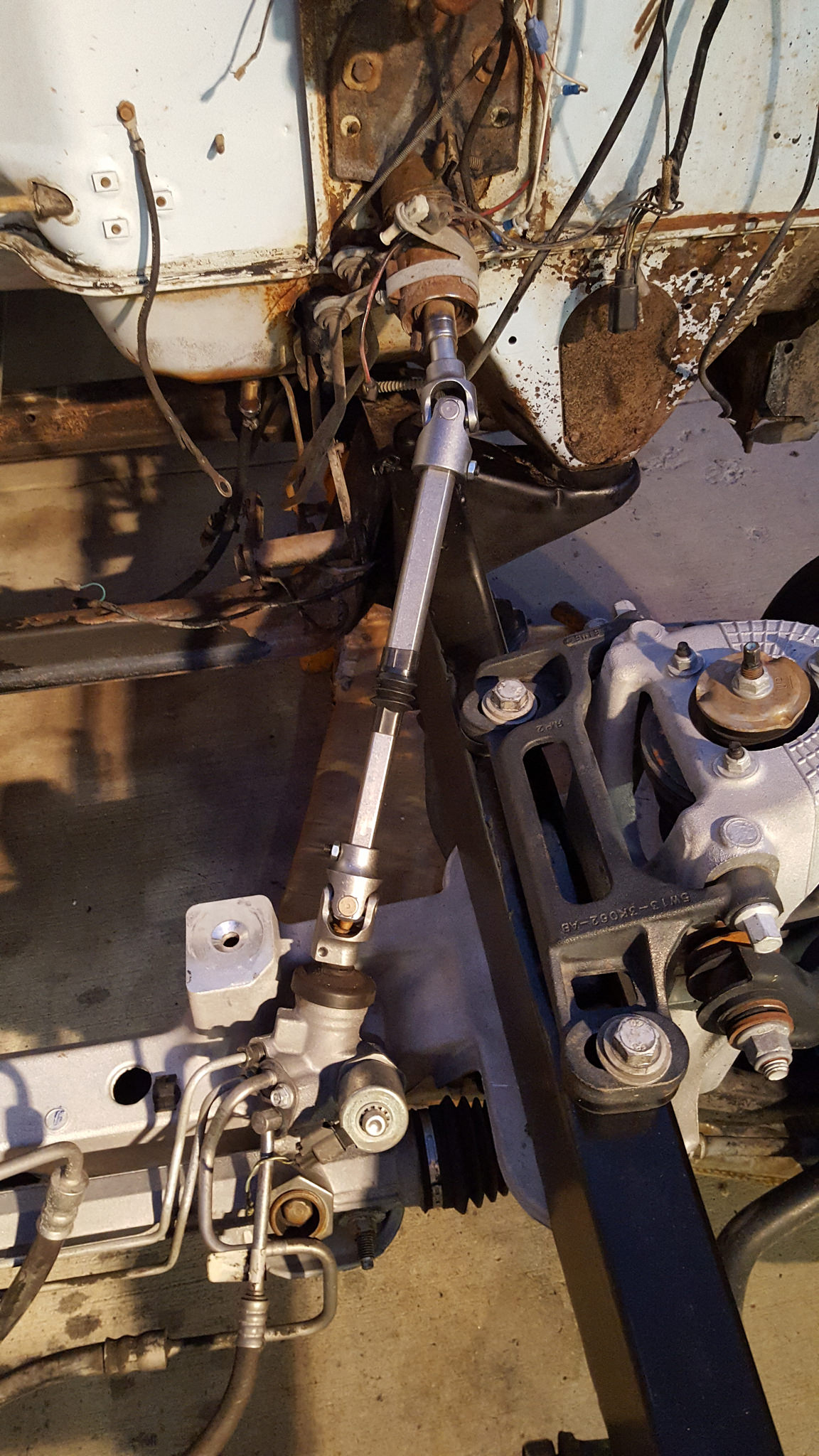
That damn POR15 took over 24 hours to dry which sucked, once it was dry I bolted the front back in and started the steering shaft
 20170919_184835 by 1SAWB, on Flickr
11-30-2017 #11
Registered User
- Join Date
- May 2017
- Posts
- 43
thank you sir Originally Posted by Protour_Pinto

I'm in Carson City Nevada, very little rust for sure
11-30-2017 #12
Registered User
- Join Date
- May 2017
- Posts
- 43
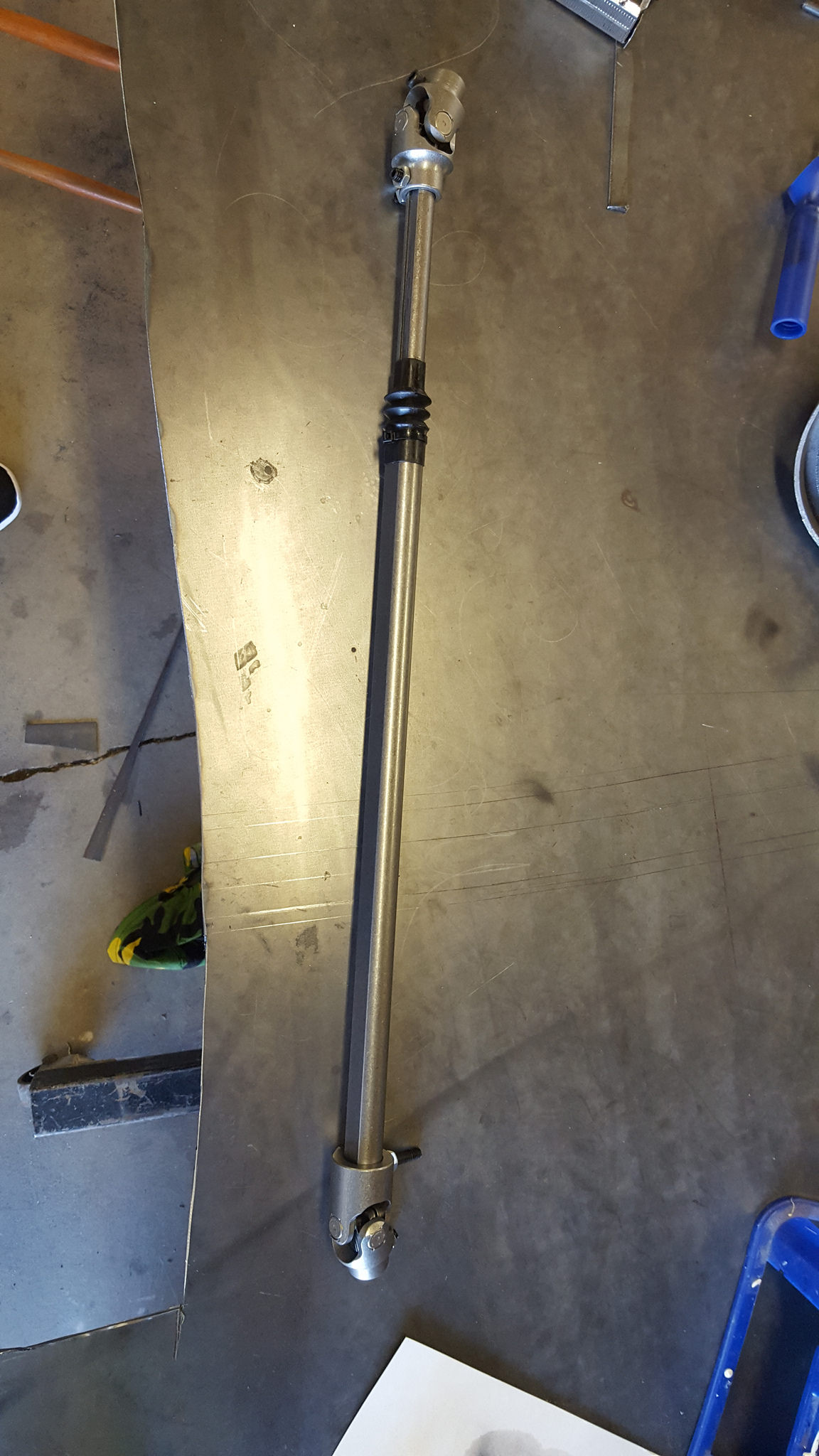
I didn't want to try and use the ugly factory weird u-joint over again so I went with the Borgeson joints and shaft. looks so nice and works flawlessly
 20170919_165459 by 1SAWB, on Flickr
 20170919_191734 by 1SAWB, on Flickr
 20170919_191727 by 1SAWB, on Flickr
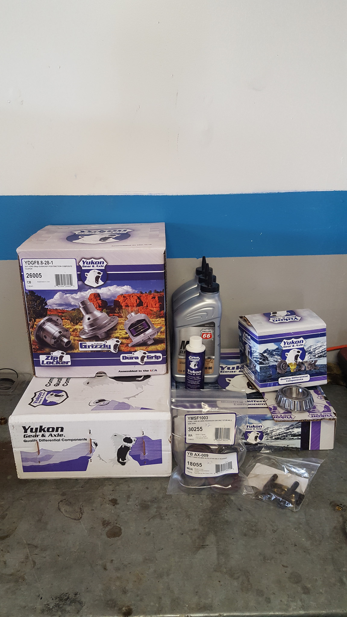
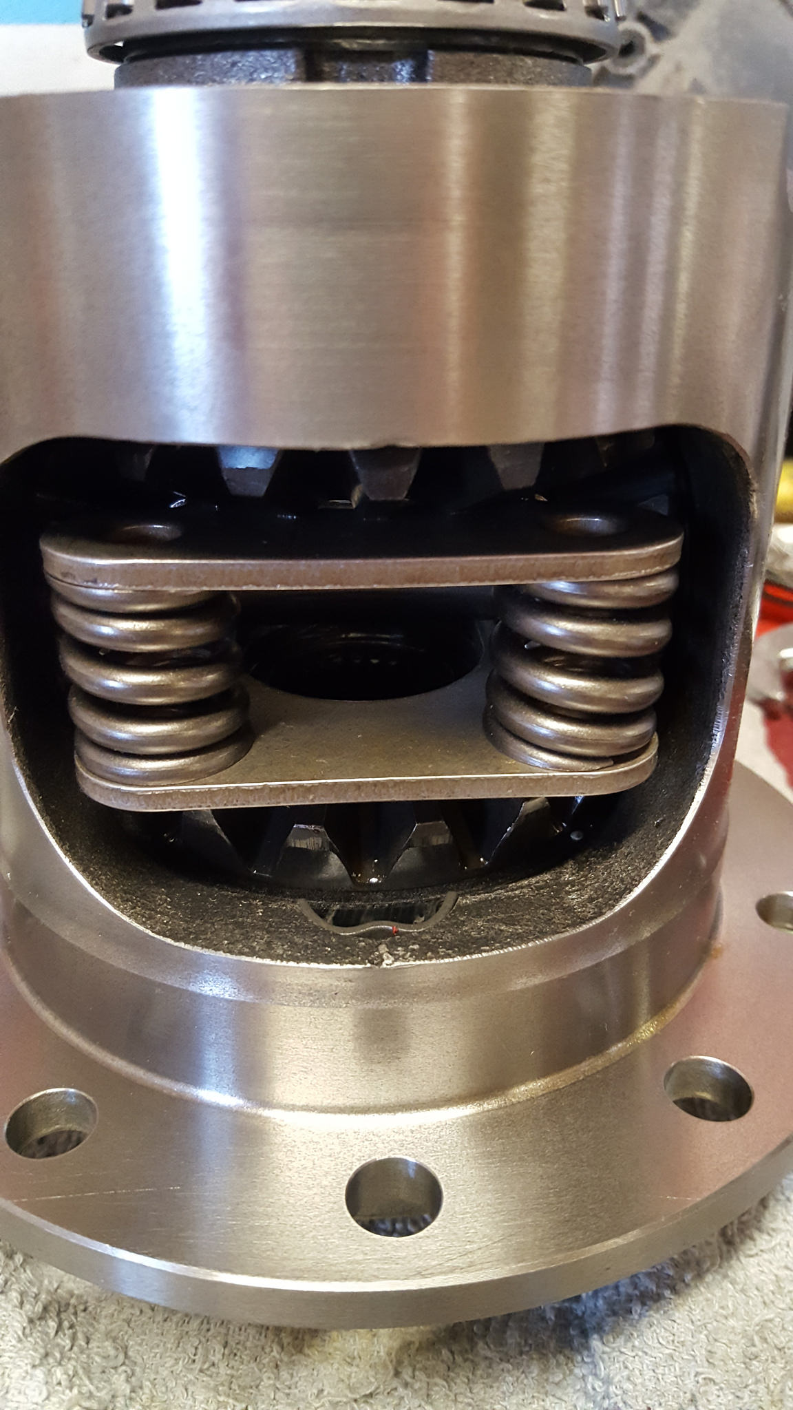
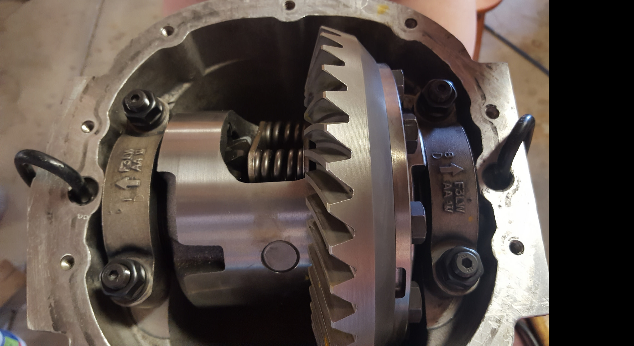
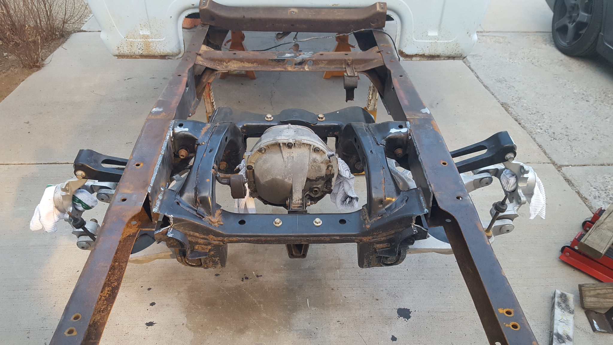
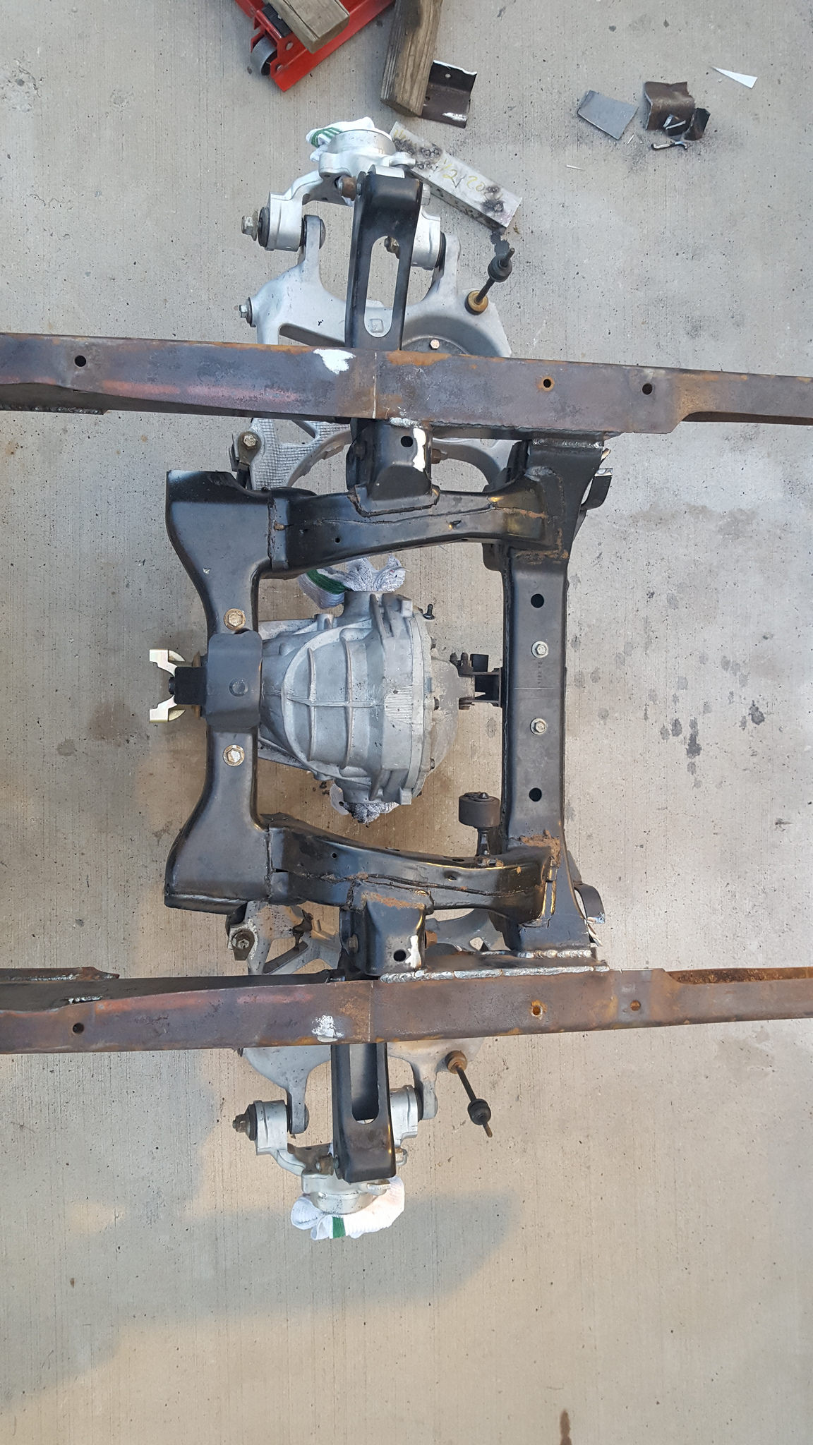
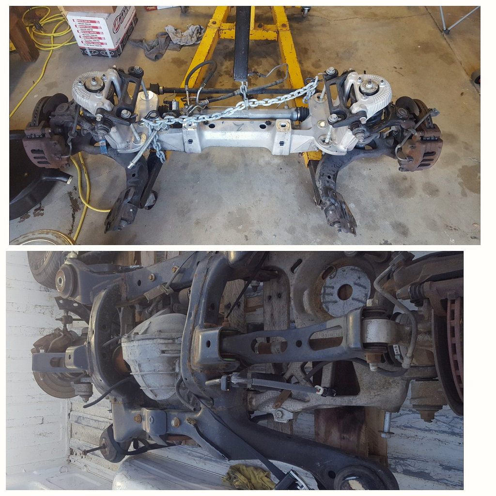
once the front was buckled up I moved onto the rear. the rear is an IRS from a 1998 Lincoln Mark VIII. this rear has aluminum 8.8 diff that I regeared to 3:55 along with a Yukon Possi unit with Carbon Fiber clutches and an upgraded 800lb spring, New bearings seals and installed ARP carrier bearing cap studs, a solid pinion spacer and topped it off with a forged 1350 yoke
 20170426_170445 by 1SAWB, on Flickr
 20170625_082821 by 1SAWB, on Flickr
 20170703_114817 by 1SAWB, on Flickr
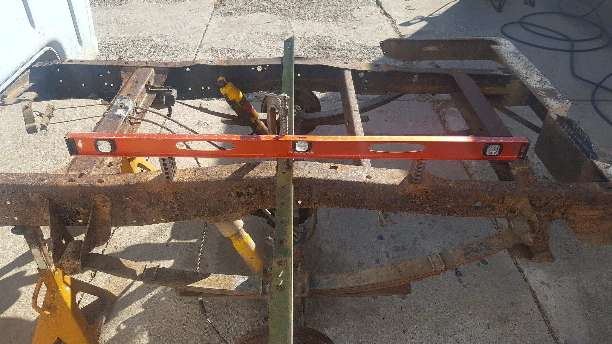
I removed the bed from the truck, leveled it as close to perfect as I could then tack welded a piece of angle iron where were axle centerline is. I made this piece wide enough so I can get out to the axle flange area
 20171007_124717 by 1SAWB, on Flickr
 20171029_145311 by 1SAWB, on Flickr
11-30-2017 #13
Registered User
- Join Date
- May 2017
- Posts
- 43
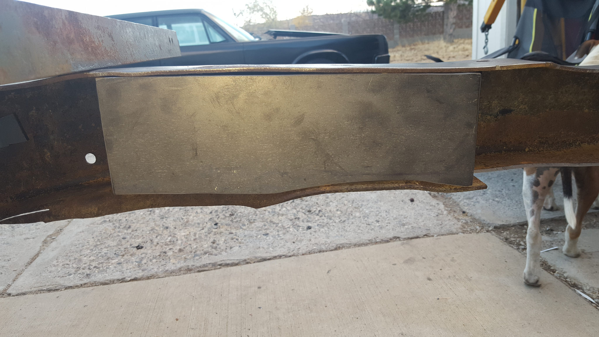
once that was done I removed all the stock suspension and sold it off to help fund this beast. while their is a "kit" to install the IRS rear I personally don't care for it. after much research I found a ton of info and decided to box the frame in the rear, cut the stock IRS cradle and weld it directly inside the frame. this will make it way stiffer compared to mounting to stock rubber mounts
 20171112_161259 by 1SAWB, on Flickr
 20171110_193055 by 1SAWB, on Flickr
11-30-2017 #14
Registered User
- Join Date
- May 2017
- Posts
- 43
IRS First cut
 20171114_183654 by 1SAWB, on Flickr
2nd
 20171114_183636 by 1SAWB, on Flickr
 20171114_183751 by 1SAWB, on Flickr
11-30-2017 #15
Registered User
- Join Date
- May 2017
- Posts
- 43
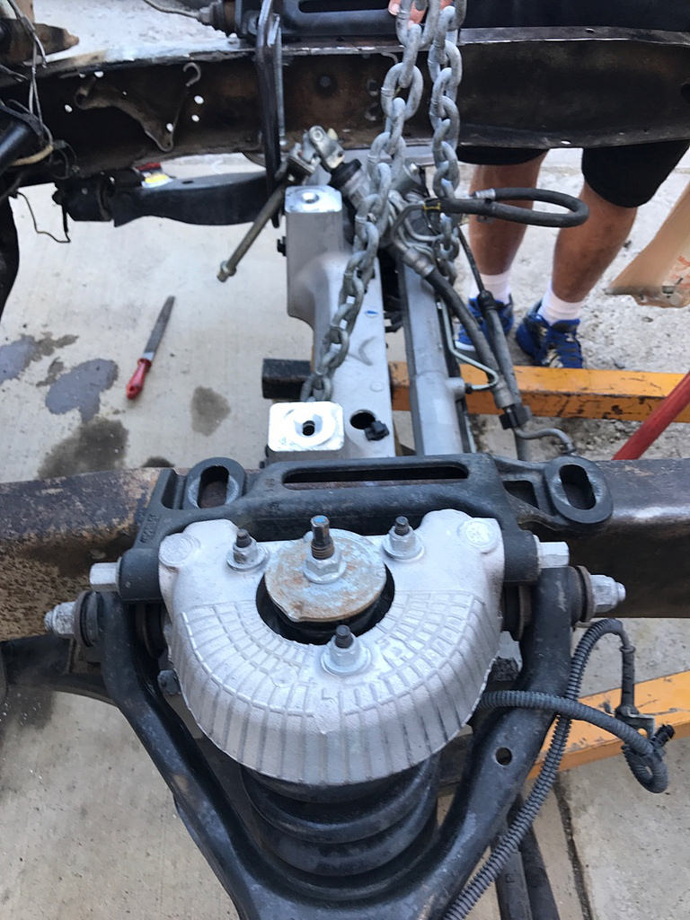
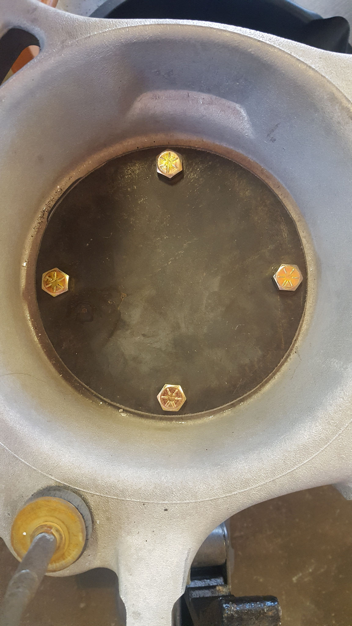
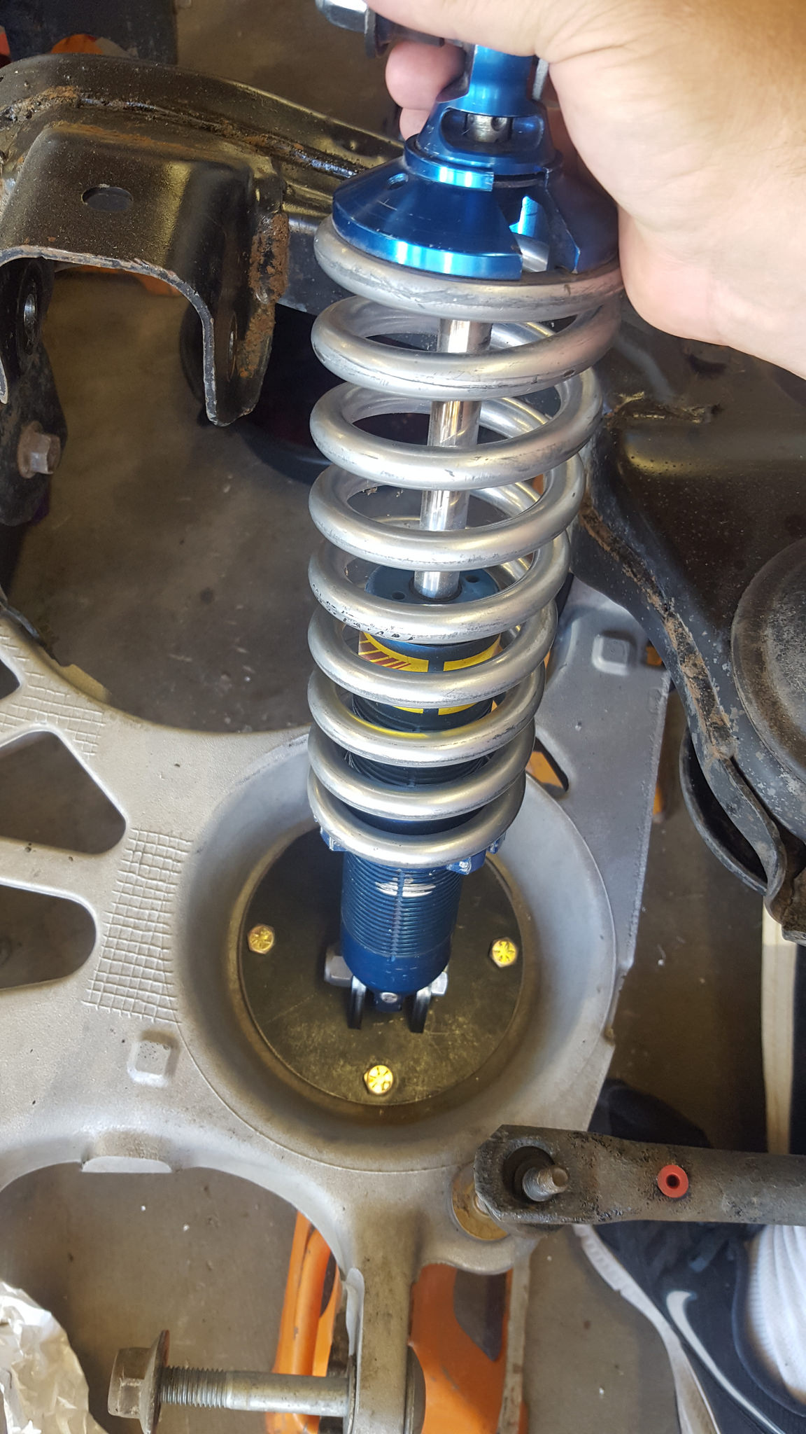
in my quest for information I had asked about rear coil overs and was told " it's impossible" this lit a fire under me to prove them wrong.....so I did. this is what I came up with. .250 plate drilled for 3/8 fasteners, drilled and tapped lower control arms that I will put a washer and nut on the bottom side just because i'm a freak like that.
 20171006_200458 by 1SAWB, on Flickr
 20171007_121004 by 1SAWB, on Flickr
 20171007_115256 by 1SAWB, on Flickr
that will do just fine
11-30-2017 #16
Registered User
- Join Date
- May 2017
- Posts
- 43
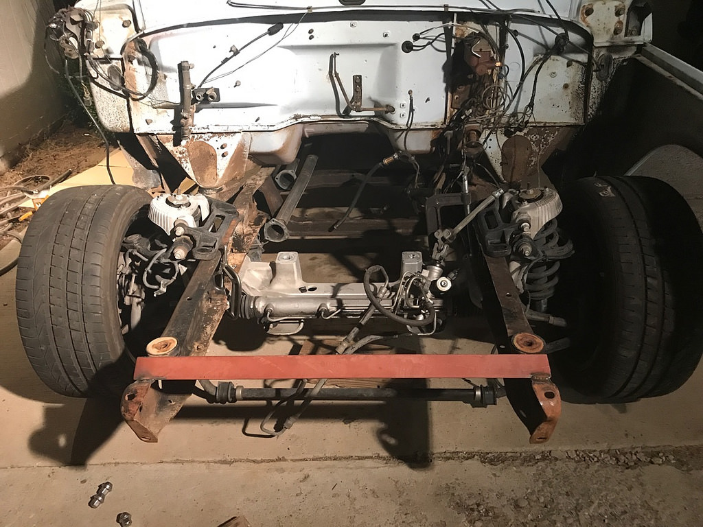
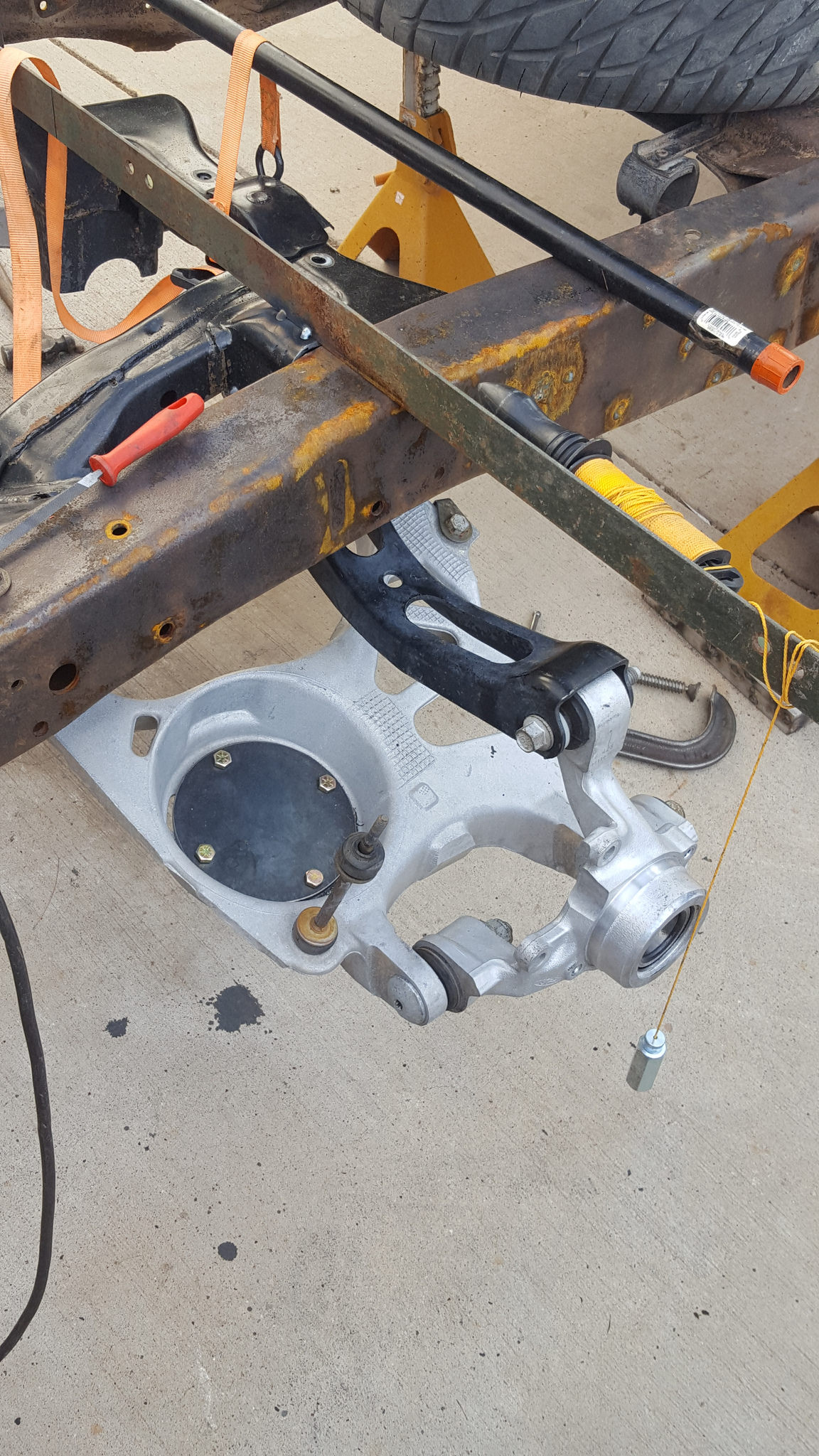
once the boxing was all done I tacked it all in and started the rear fitment. just about everything went as planned
 20171118_144729 by 1SAWB, on Flickr
 20171118_144708 by 1SAWB, on Flickr
11-30-2017 #17
Registered User
- Join Date
- May 2017
- Posts
- 43
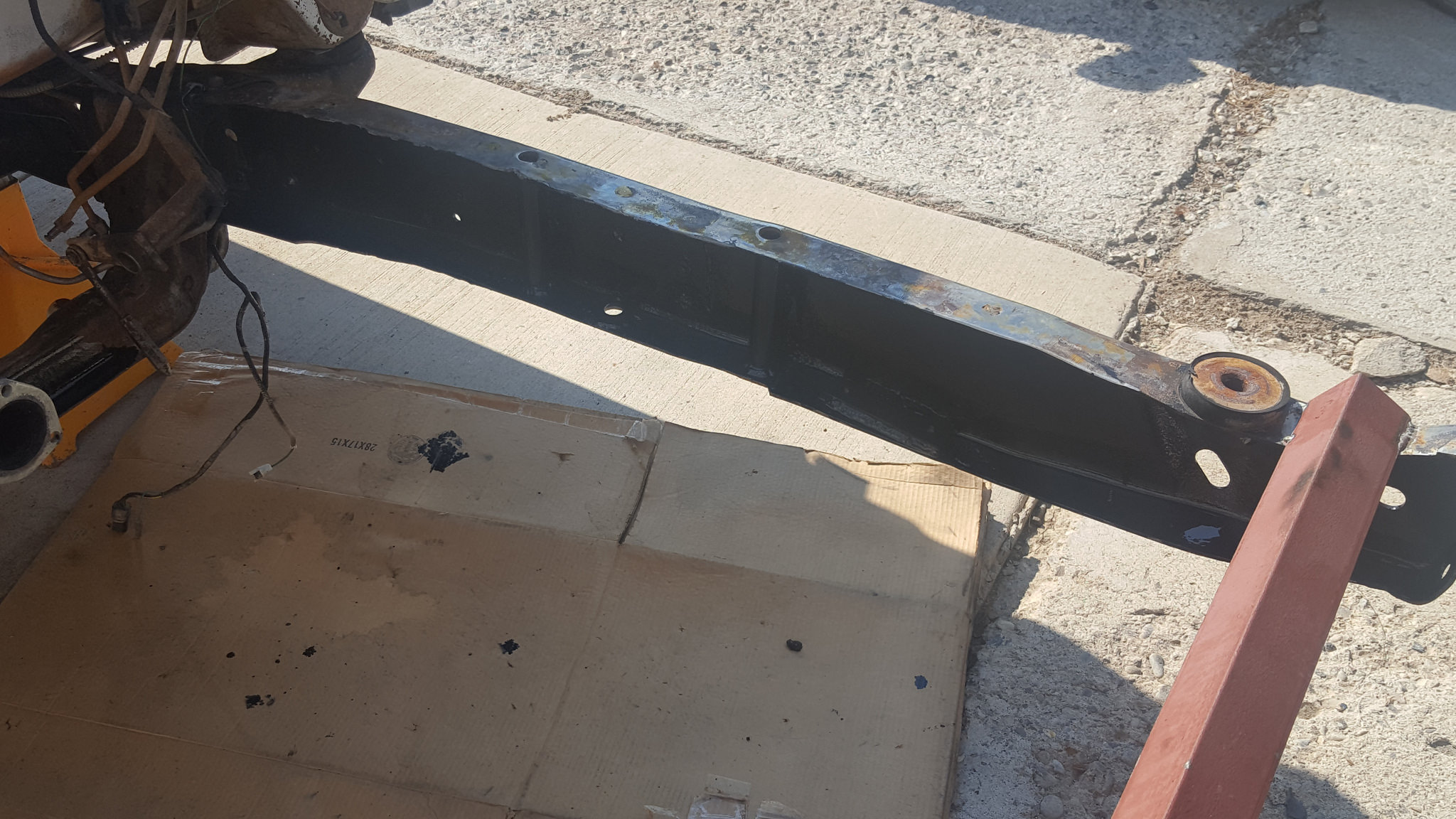
after 100's of times measuring, making sure the sub frame was centered, wheelbase was right and pinion was where I wanted it, it was time to fire up the welder and get burning it in. after miles of welding here she is
 20171125_162105 by 1SAWB, on Flickr
 20171125_162136 by 1SAWB, on Flickr
11-30-2017 #18
Registered User
- Join Date
- May 2017
- Posts
- 43
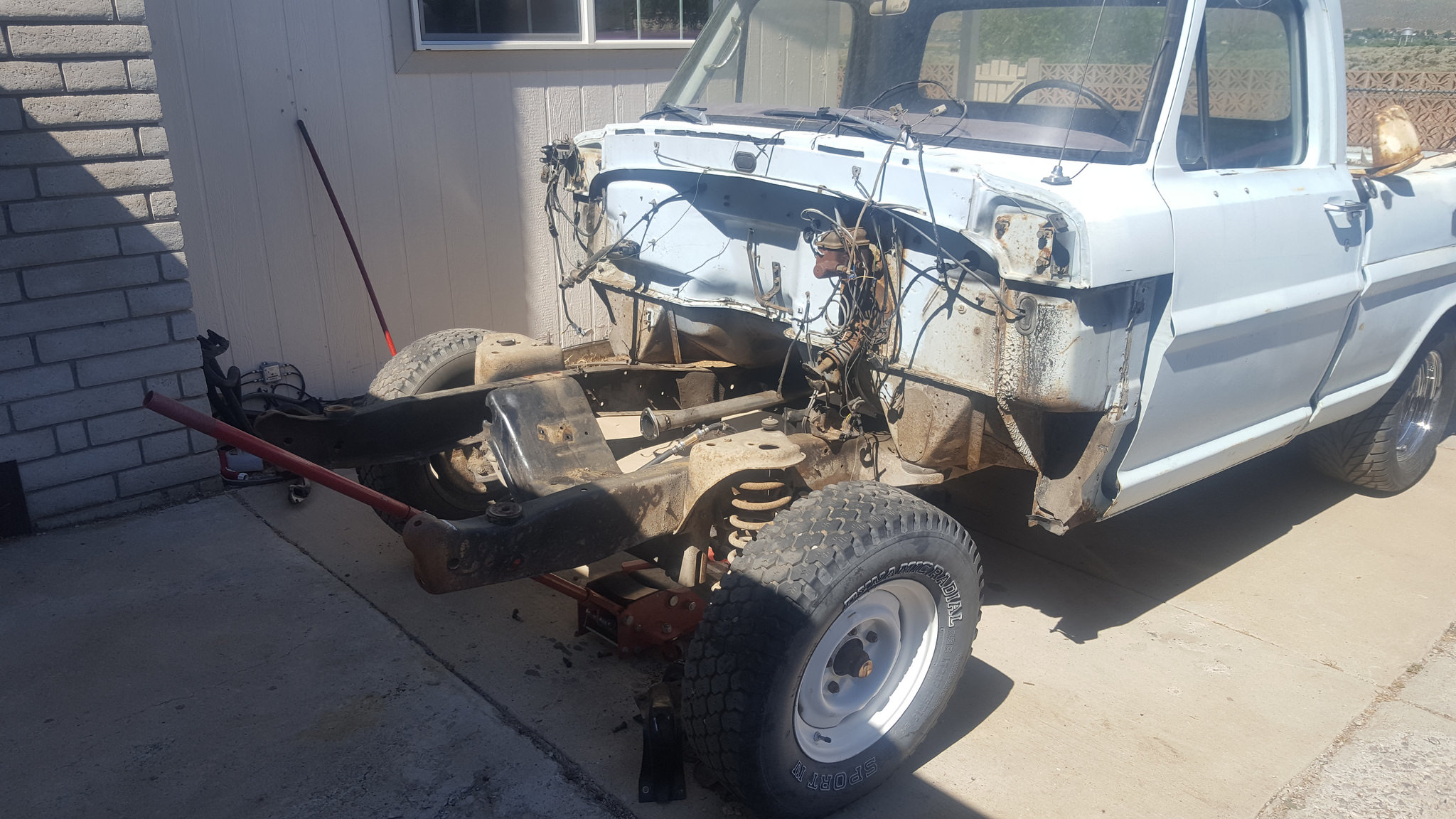
after mocking the upper arms and knuckles up I knew I needed to notch the frame to clear the upper. After doing this I math out how much the needed to be notched. I made it so that if one day I wanted to bag it, it would lay the cab on the ground
 20171125_130746 by 1SAWB, on Flickr
 20171125_134713 by 1SAWB, on Flickr
11-30-2017 #19
Registered User
- Join Date
- May 2017
- Posts
- 43
Now I need to finish the notch. fill in the front portion of the sub frame and redrill the rear bolt pattern from the stupid 5 x 4.25 to 5 x 4.5 for the wheels
12-01-2017 #20
Registered User
- Join Date
- May 2017
- Posts
- 43
before pic of the IRS and IFS
 2017-11-30_11-12-28 by 1SAWB, on Flickr
little elbow grease went a looong way
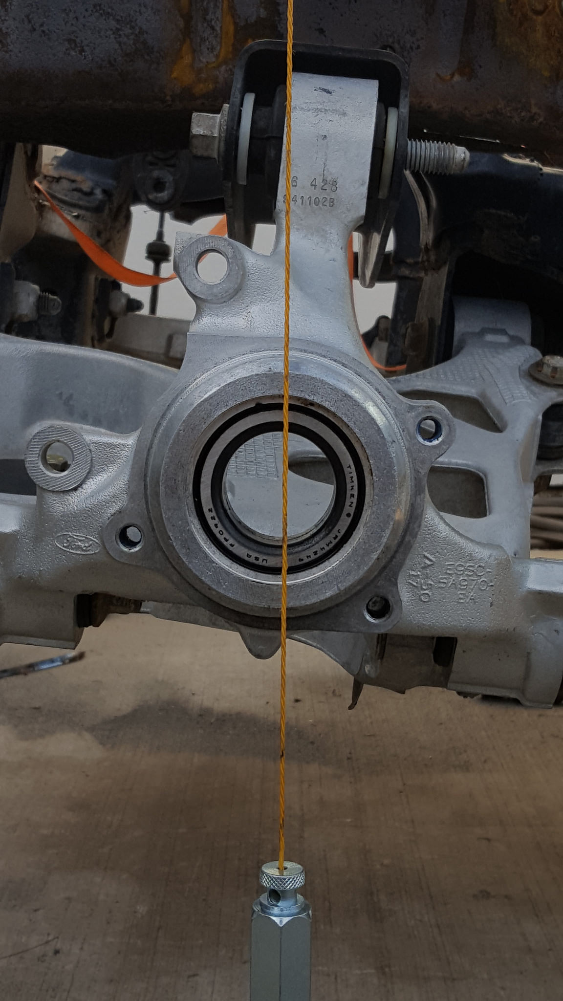
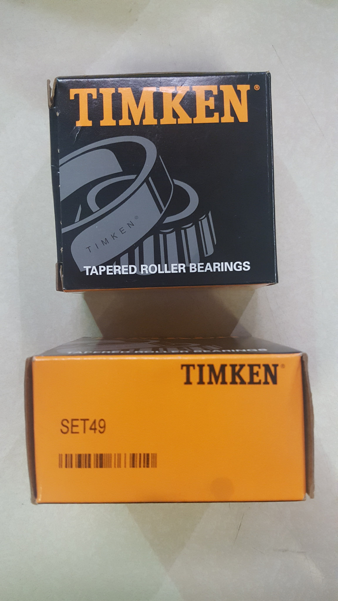
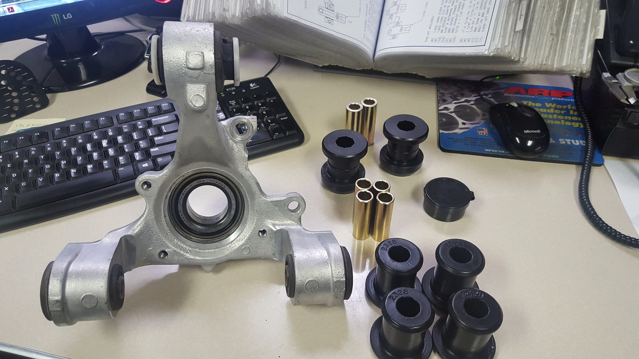
once the IRS was torn down I found a bad wheel bearing so I tore into the knuckle and replaced both bearings, since I need to change the bolt pattern I figured what better thing to use the ARP screw in Wheel Studs and urethane bushing's
 20170908_092140 by 1SAWB, on Flickr
 2017-11-30_07-12-14 by 1SAWB, on Flickr

 Reply With Quote