

Results 1 to 20 of 28
Thread: I need custom ideas.
-
07-16-2017 #1

 Registered User
- Join Date
- Jun 2010
- Location
- Deployed
- Posts
- 3,280

I need custom ideas.
So I had everything the way I wanted it, but now I have the LS7 and the GM fuse box, I need to figure out how to get this 6ga wire and power to the box. I need your ideas on not only how to do this but look decent too rather then a wiring mess. I thought about splices right at the alternator main wire to stud junctions in between....help
1970 Camaro/DSE build
Are you driver enough? Maybe....come on blue!
https://www.pro-touring.com/threads/...71#post1147371
-
07-16-2017 #2 Registered User
- Join Date
- Sep 2006
- Posts
- 273
Can you Come off the starter constant power ????
07-16-2017 #3
Registered User
- Join Date
- Jun 2010
- Location
- Deployed
- Posts
- 3,280
 Originally Posted by IMPALAMAN1

Yeah, I could but it's more length of wire. I was hoping to keep the length of wire from source to the box as short as possible.
What if I join the cars fuse box wires to the LS box wire and run a 4 ga back?1970 Camaro/DSE build
Are you driver enough? Maybe....come on blue!
https://www.pro-touring.com/threads/...71#post1147371
07-16-2017 #4
Registered User
- Join Date
- Jun 2010
- Location
- Deployed
- Posts
- 3,280
Basically all wires on this 1/4" post and run a 4ga to a stud where the battery charge, alternator and this wire come together?
1970 Camaro/DSE build
Are you driver enough? Maybe....come on blue!
https://www.pro-touring.com/threads/...71#post1147371
07-16-2017 #5
Registered User
- Join Date
- Jun 2010
- Location
- Deployed
- Posts
- 3,280
Ok, Will this work?
1. Eliminate the purple wires (3) 10-12 ga wires. Shorten them to about 4 inches and attached them to the 1/2" studs on the LS fuse box (They are fused)
2. Run a 4 ga power wire from the 1/4" stud to the green 3/8" post stud on the firewall.
3. Attach the 4 ga alternator wire to the green 3/8" stud
4. Attach the 4 ga charge wire to the green 3/8" stud
In my mind I think I just shortened the length of travel?? Thoughts? This will clean it up a little.1970 Camaro/DSE build
Are you driver enough? Maybe....come on blue!
https://www.pro-touring.com/threads/...71#post1147371
07-16-2017 #6
Registered User
- Join Date
- Jun 2010
- Location
- Deployed
- Posts
- 3,280
1. Green Arrow are power wires from LS fuse box to power the OEM vehicle fuse box
2. Light Arrow, eliminated fuse box wires from alternator splice to re-locate as stated in #1.
3. Thick red is 4 Ga wire
4. Dark Blue Arrow is 4 GA wire now powering both OEM and LS fuse box.1970 Camaro/DSE build
Are you driver enough? Maybe....come on blue!
https://www.pro-touring.com/threads/...71#post1147371
07-16-2017 #7
Registered User
- Join Date
- May 2010
- Location
- kitchener,Ontario,Canada
- Posts
- 2,336

Really anything will work ...id say more importantly do you want to hide the wires, if so then I'd say do it but that changes the length more times then not so now you must step up the wire size
 Spinnin'my tires in life's fast lane
Ryan Austin
On twitter @raustinss
On Instagram austinss70
07-16-2017 #8
Registered User
- Join Date
- Jun 2010
- Location
- Deployed
- Posts
- 3,280
It's almost staying the same, the part that I'm really over thinking is the 4ga able the feed both both boxes??
The 3 wires are currently spliced into the 4ga going to the alternator. I would change that to a 4ga and route it to feed both boxes instead of the thre wires and a a 6ga running parallel to each other1970 Camaro/DSE build
Are you driver enough? Maybe....come on blue!
https://www.pro-touring.com/threads/...71#post1147371
07-16-2017 #9
Registered User
- Join Date
- Jun 2010
- Location
- Deployed
- Posts
- 3,280
Schematic
1970 Camaro/DSE build
Are you driver enough? Maybe....come on blue!
https://www.pro-touring.com/threads/...71#post1147371
07-18-2017 #10
Registered User
- Join Date
- Jun 2010
- Location
- Deployed
- Posts
- 3,280
Why do these sites lack feedback to questions like this? Seems I can't use these forums as sounding board anymore....
Do only a few people frequent these sites now?1970 Camaro/DSE build
Are you driver enough? Maybe....come on blue!
https://www.pro-touring.com/threads/...71#post1147371
07-19-2017 #11 Registered User
- Join Date
- Apr 2006
- Location
- Atlanta, GA
- Posts
- 128
OK- Originally Posted by badazz81z28
Here's what I would do-
I'd home-run the alternator's output to the battery(or starter lug)- and fuse there - If the alternator jumps ship- throws AC- surges voltage -it can torch your electronics.
I'd run the electronics off the battery- as the battery does more than just start your car- it stabilizes voltage and filters- electronics like that!!!
Richard
07-19-2017 #12
Registered User
- Join Date
- Jun 2010
- Location
- Deployed
- Posts
- 3,280
Originally Posted by Richard454
The battery is in the trunk. Running a 4ga wire back to it would just cause me more money and unnecessary work not the mention voltage drop. The battery and the alternator are part of the circuit so no matter where I jump in the alternator is part of the equation. Alternators have Voltage regulators and I haven't seen one yet that fried electronics and in not really concerned about that. I'm looking for these best way to tie it all together. I think I'm just going with a stud junction on the firewall.1970 Camaro/DSE build
Are you driver enough? Maybe....come on blue!
https://www.pro-touring.com/threads/...71#post1147371
07-20-2017 #13
Registered User
- Join Date
- Apr 2006
- Location
- Atlanta, GA
- Posts
- 128
Just trying to help you out- Originally Posted by badazz81z28
Yes- alternators do have voltage regulators- but that has nothing to do with the actual voltage of the car. The alternator is your income- the battery is your bank account- and at idle the alternator is not going to be putting out the required current to start up the electric fans- the voltage drops- not a good scenario for the electronics down wind. Does it sound like a good idea to pay your mortgage with your paycheck if you are only working part time?? And the voltage drop on copper wire running the length of your car to the battery is less than ½%...Just saying.
I also said 'starter lug'- you can use that as terminal- and home run the alternator wire there. That's what I recommend- as this isn't my first rodeo...
If you want a nice terminal post cheap-you can get a real nice one at the junkyard- look at the big (5&7 series) mid 90's BMW's-they are some of the best ones-
Or look at some marine stuff- a little bit more expensive (less than $75 for the 4 terminals in the picture)
NOW- make sure what ever you use- alternator- posts- the the ring terminal fits tight around the stud- other wire it'll arc after a while and make a lousy connection.
I've used these type of terminals too- but only for smaller circuits-
07-20-2017 #14 Registered User
- Join Date
- Mar 2015
- Location
- FL
- Posts
- 318
The main concern is noise rejection for the power wires to the ECU. The battery is a stable voltage reservoir. You don't have it shown on your diagram but where is the ECU powered from? Closer to battery the better. General rule for power supply of the other electronics as well. Which the bulkhead in your diagram can essentially be considered the battery positive for most things (except for the ECU power source--some would argue-see below).
I'm sure you could look up a wiring diagram somewhere (or someone can pipe in) some of these questions.
FYI. I recently installed a FAST XFI 2.0 efi system and the directions were very insistent about connecting the positive and negative of the ECU directly to the battery. Here's what the directions said:
"2.1.7 BAT+ and BAT-
The battery wires should only be connected to the battery terminals, not to an intermediate power source or ground on the chassis or engine. This will ensure maximum noise rejection from ground loops and conducted noise."-Mitch
G8 GXP, White Hot, Auto, bone stock
68 Firebird, 428 Pontiac, CNC'd KRE Al d-ports, hyd roller, EFI, TKO600, TCI Eng complete chassis, Ridetech, Kore3 C6Z brakes, C5Z 18" with 315 rivals x4, C6zr1 mufflers
RRR, NASA HPDE https://youtu.be/DPp1l9-FuNE
07-20-2017 #15
Registered User
- Join Date
- Apr 2006
- Location
- Atlanta, GA
- Posts
- 128
"Noise rejection" Exactly Mitch- Originally Posted by gator68428
For those that think it doesn't matter- take a good meter ( not the free one from Harbor Freight) Put it on AC voltage. While the car is running- see what the meter reads at the battery and then at the back of the Alternator-you will see two to three times the ripple or AC current at the back of the alternator. Oh- and load up the alternator and you'll see you have even more AC ripple.
07-20-2017 #16
Registered User
- Join Date
- Mar 2015
- Location
- FL
- Posts
- 318
I think the solution for your firewall wires it to route them inside the car.
For aesthetics it's better not to have any of those wires visible if possible.
Feed them through the firewall on the drivers side and then cross over to the passenger side.-Mitch
G8 GXP, White Hot, Auto, bone stock
68 Firebird, 428 Pontiac, CNC'd KRE Al d-ports, hyd roller, EFI, TKO600, TCI Eng complete chassis, Ridetech, Kore3 C6Z brakes, C5Z 18" with 315 rivals x4, C6zr1 mufflers
RRR, NASA HPDE https://youtu.be/DPp1l9-FuNE
07-21-2017 #17
Registered User
- Join Date
- Jun 2010
- Location
- Deployed
- Posts
- 3,280
I feel when you see companies like FAST EFI or SPAL fans etc tell you to attach directly to the battery is because it eliminate the "electrical dumb" people mistakes. If you didn't connect it to the battery, you would see some people splicing power from who knows where...which could or could not work creating too much liability.
The ECU of the OEM LS engine doesn't have a red POS battery source attached to it. Same with the ground...they are attached to the harness and positioned to attached tto the back of the heads. Quite different....
All the power to operate the LS engine ECU comes from a the fuse box in any production car and how mine is wired. The power comes in from the main power circuit and its distributed.
I would argue the alternator does put out the voltage and amperage to power the car at idle and even without a battery. The car doesn't run off the battery and it fact when the car is running you can physically remove the battery from the circuit and everything will stay running. A lot of people only have a 10ga wire running to the battery for only charging purposes. Heck some things like certain aircraft don't even have batteries and run solely on PMGs.
I don't claim to be an electrical expert, but I know the basics enough to know if I have closed circuit that contains a battery an alternator and a starter as junctions, it makes no difference where I splice into it. Attaching it to the starter lug is no different then attaching it to the alternator lug. What comes into play is voltage drop dependent on wire gauge and length.1970 Camaro/DSE build
Are you driver enough? Maybe....come on blue!
https://www.pro-touring.com/threads/...71#post1147371
07-21-2017 #18
Registered User
- Join Date
- Mar 2015
- Location
- FL
- Posts
- 318
I'm no expert either and I'm always open to understanding how and why. First step is to start with where the engineers left off before leaving ourselves up to our own vacuum.
You're probably right, running directly to the battery or not may not be critical. That's how I have the system wired in my Firebird (not the FAST---an old Mass Flo EFI from 2007 that is a 92 Ford Mustang ECU) and at the time I installed the system, Mass-flo nor I worried too much about connecting to the batt directly and seems to work fine--and I think my alt is connected between fusebox and batt... However I will say that I did have a debilitating electrical noise issue that was solved by shielding particular wires--so I do appreciate noise sensitivity concerns first hand--but no, the ECU not being connected to the batt wasn't the cause of the noise in that case. But I'm in the midst of more mods to the Firebird and I will update for best practices.
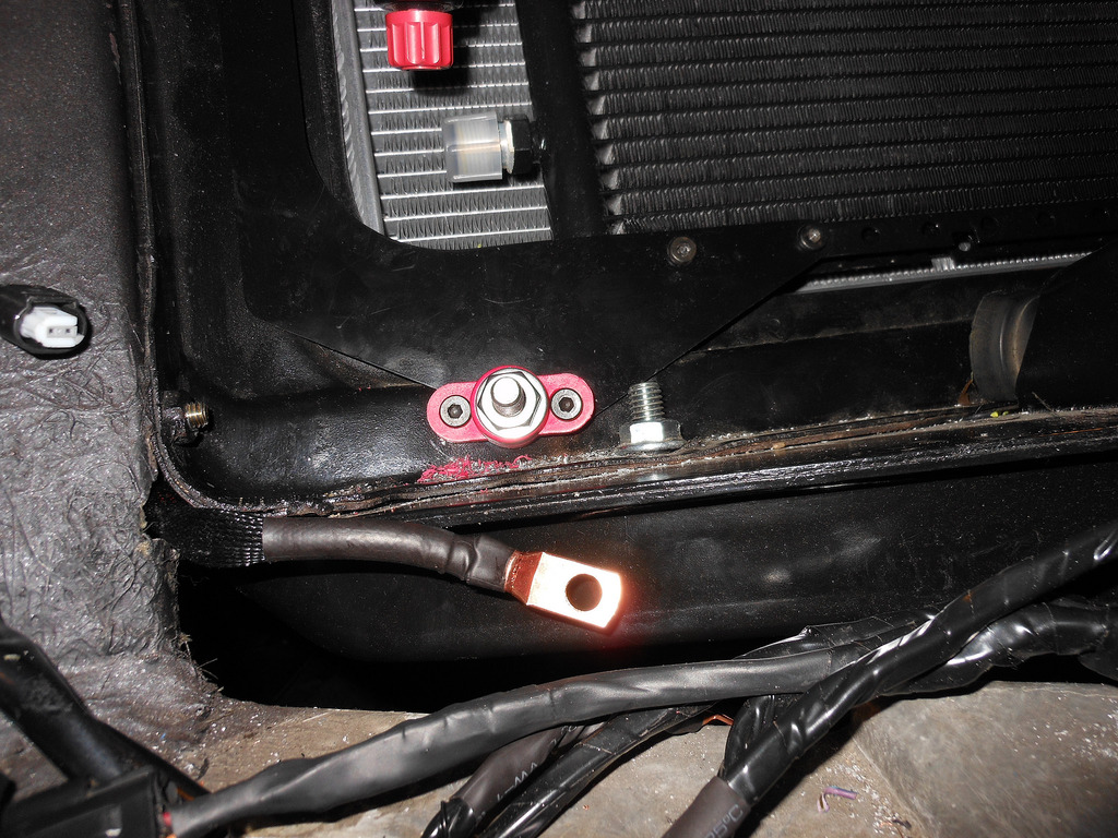
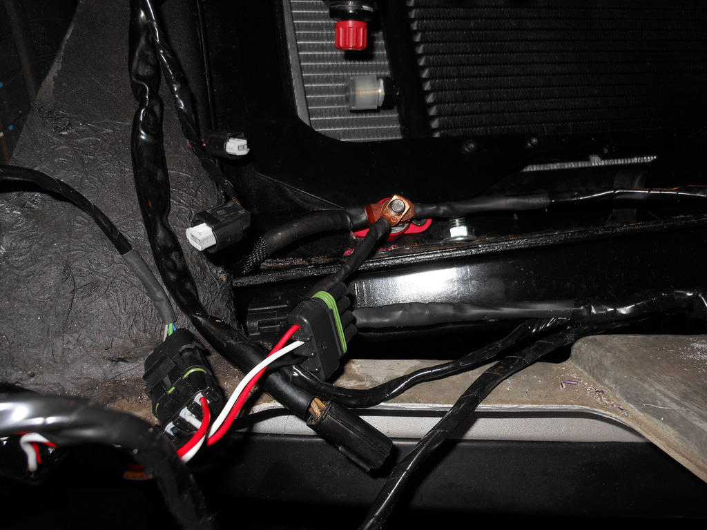
This brings me to an open question that may be relevant to this discussion. My 2009 G8 GXP (LS3) has a trunk mounted battery from the factory. At the positive terminal there are 2 medium gauge (fused) wires connected in addition to the fat starter wire. The fat starter wire runs unimpeded to a bulkhead in the engine compartment for easy jumping and starter connection. I'm not sure if ECU or fusebox power is pulled from somehwhere between the bulkhead and starter or from the two medium gauge wires at the batt terminal. Whatever the case, even in a trunk mounted battery, they went through some extra effort to add additional wires to the terminal. Anyone got access to any wiring diagrams help understand?
Pics below. Don't mind the two black wires connected to pos terminal--those are aftermarket...

-Mitch
G8 GXP, White Hot, Auto, bone stock
68 Firebird, 428 Pontiac, CNC'd KRE Al d-ports, hyd roller, EFI, TKO600, TCI Eng complete chassis, Ridetech, Kore3 C6Z brakes, C5Z 18" with 315 rivals x4, C6zr1 mufflers
RRR, NASA HPDE https://youtu.be/DPp1l9-FuNE
07-21-2017 #19
Registered User
- Join Date
- Mar 2015
- Location
- FL
- Posts
- 318
Looking at the engine compartment pic of the G8 you can see there is a second smaller gauge wire coming off the bulkhead.
Natural question is: Does it go to a fusebox or to the alternator?
Answer: I just popped the hood and followed that wire and it seems to terminate at the alternator.
Therefore, it seems the two wires coming off the pos bulkhead in the engine compartment are 1) the starter power, and 2)the alternator.
Next level of analysis would ask: Does ECU and fuse box connect from some common at the starter or alternator? Or back in the trunk at batt?
The saga continues...-Mitch
G8 GXP, White Hot, Auto, bone stock
68 Firebird, 428 Pontiac, CNC'd KRE Al d-ports, hyd roller, EFI, TKO600, TCI Eng complete chassis, Ridetech, Kore3 C6Z brakes, C5Z 18" with 315 rivals x4, C6zr1 mufflers
RRR, NASA HPDE https://youtu.be/DPp1l9-FuNE
07-21-2017 #20
Registered User
- Join Date
- Jun 2011
- Location
- Brooklyn, NY
- Posts
- 195
I like to run wires where they are not seen. So my fuse box wire goes from the firewall, through the fender, down the radiator support to the junction box i mounted on the fender well below the battery. alternator wire runs from there to up the block behind the water pump to the back of the alternator. fans also grab power from the same point.
i like to use factory stuff whenever possible, so i re-used the truck power cables that came with my motor. shortened the alternator cable, and used the truck junction box as the point of distribution. there will already be cables running from battery to block and battery to starter, i run the alternator cable along same path just up the block to the alternator.
fan relays are mounted to an L shaped bracket which is then mounted to the underside of the fender so that relays are horizontal and out of sight.
just realized picture looks like im grabbing starter wire from the junction box but im not, just meant to say the wires are zip-tied together going down to the block.


 Reply With Quote


