

Results 361 to 380 of 808
-
06-22-2018 #361

 Registered User
- Join Date
- Sep 2009
- Posts
- 2,707

Thanks Carl, I appreciate the compliment! You have no idea how hard I'm resisting to just pull the trigger and put the rest of the parts I need on my credit card...
Thanks Clint! I looked at it really quick last night when I was "walking the dog", and I think it's going to take a combination a sway bar spacer and relocating the tensioner up higher. Right now, if I was to just space it down, I'm looking at about a 2-2.5" spacer... Not sure that would be good. Plus it wouldn't give me any room to grow if I wanted a 1 1/8" bar like you have.
1955 Nomad project LC9, 4L80e, C5 brakes, Vision wheels
1968 Camaro 6.2 w/ LSA, TR6060-Magnum hybrid and etc SOLD
1976 T/A LS1 6 Speed, and etc. SOLD
Follow me on Instagram: ryeguy2006a
-
06-22-2018 #362
 Registered User
- Join Date
- Nov 2010
- Location
- Ventura County CA
- Posts
- 556
Spacing the swaybar downward 2-2.5" would likely create problems. The sway bar mounts could interfere with the lower control arm during bump travel and the center of the sway bar would interfere with the center cross member on the frame. Also the sway bar end links would need to be very short.
Looking at photos it seems like the tensioner could be relocated closer to the crank pulley and upward, providing more clearance for the swaybar. I'm not sure what the bracket looks like but maybe you can modify it to move the tensioner mounting pad?
I am curious if the bends in your stock bar are in the same location as my Helwig bar. if the bends were located more outward on an aftermarker bar, you might have more clearance when you change sway bars.Clint - '70 Nova "restomod" cruiser & autocross family car
-
06-25-2018 #363
Registered User
- Join Date
- Sep 2009
- Posts
- 2,707
Thanks for the input Clint. After looking back at your build, there is no way that I could space the bar down that far. You were approaching interference issues with just 1/2" spaced down. I got to looking at this a little on Saturday and I'm thinking I may just put this on the back burner for now as it may not be worth messing with it until I can get an aftermarket sway bar. That is an interesting point about the possible difference in the locations of the bends on the sway bars. Would you mind measuring from the mounting point on the frame to where the bar starts to bend? That's about the only solid point I could see taking a measurement from that may be consistent. Originally Posted by TheBandit

1955 Nomad project LC9, 4L80e, C5 brakes, Vision wheels
1968 Camaro 6.2 w/ LSA, TR6060-Magnum hybrid and etc SOLD
1976 T/A LS1 6 Speed, and etc. SOLD
Follow me on Instagram: ryeguy2006a
-
06-25-2018 #364
Registered User
- Join Date
- Sep 2009
- Posts
- 2,707
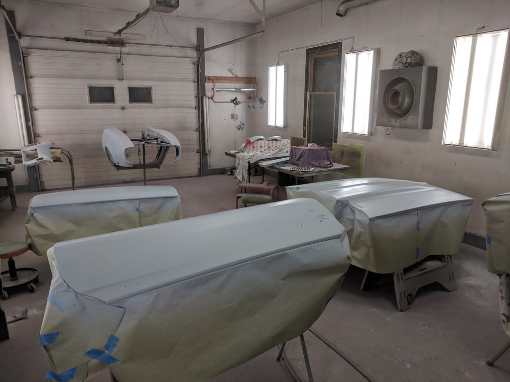
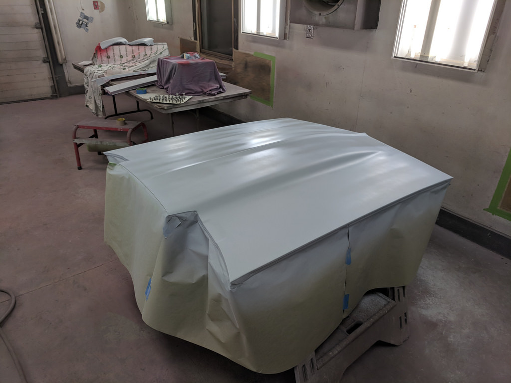
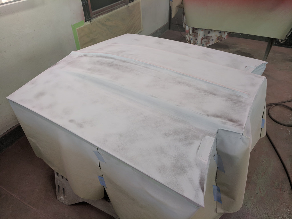
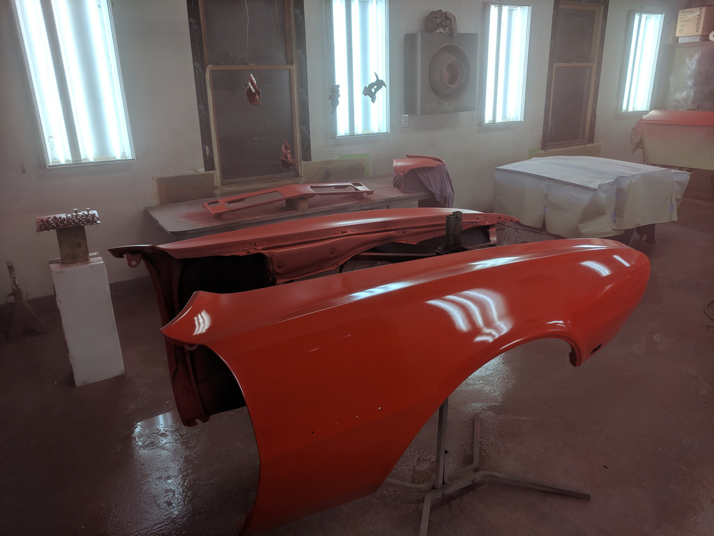
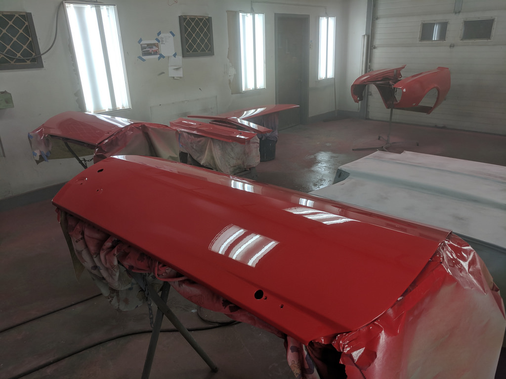
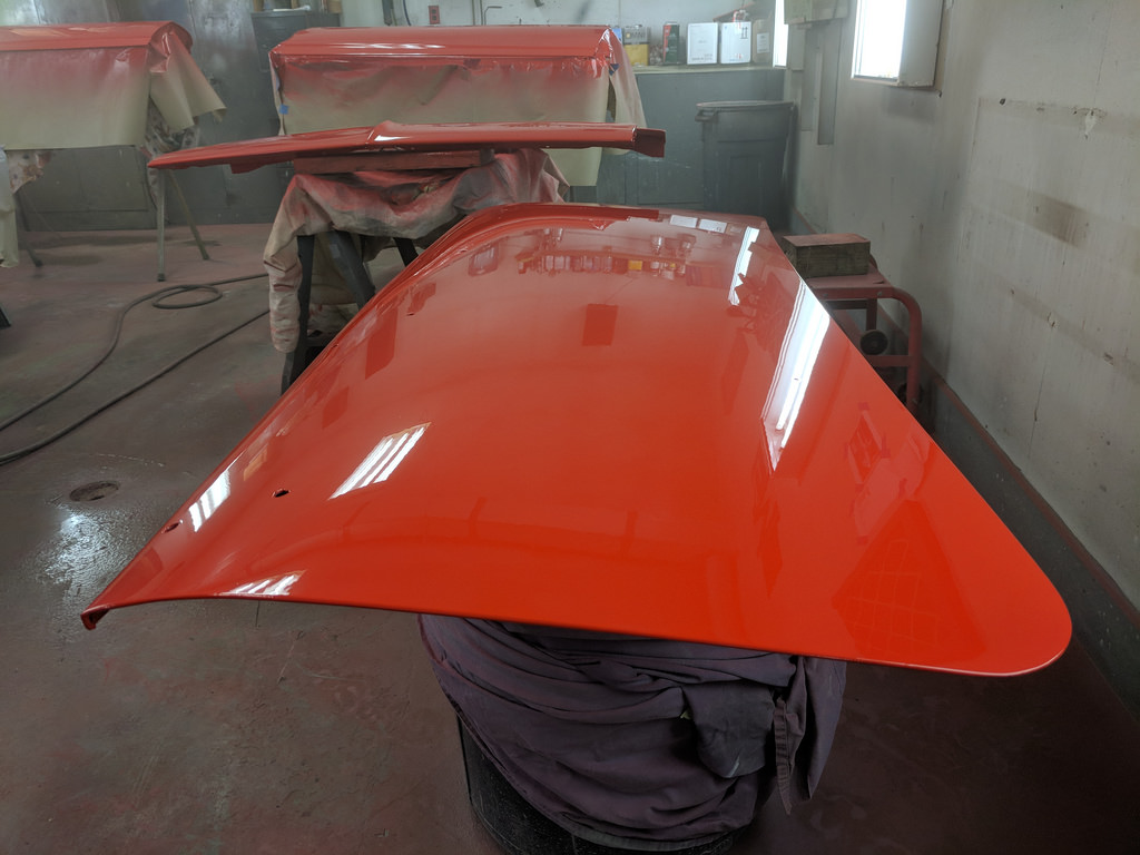
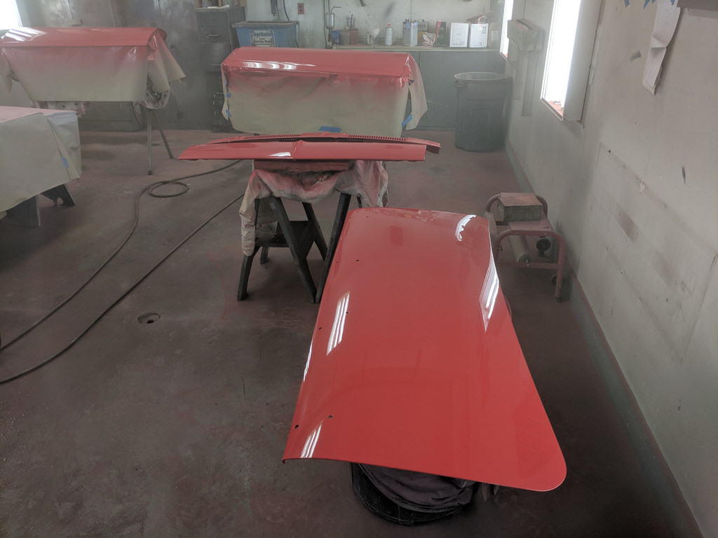
My son had a play date Saturday morning with some of my wife's friend's kids that are the same age as my son, so I had the green light to work on my old Camaro. I didn't waste any time getting to work. I was determined to do all of the spraying on these panels now that I was a little more comfortable. I got to work prepping the bottom sides of the panels for some paint. I had a few area's on the bottom of the deck lid that lifted the paint, so I had to sand that down further and re-spray. Thankfully the underside of the hood just needed to be scuffed up and shot. Once all the panels were ready to be sprayed, I had to clean all the dust out of the room by spraying everything off, then waiting for the dust to settle. I started off by spraying the doors because they just needed a scuff down the existing clear coat to prep for a few coats of epoxy for good adhesion.
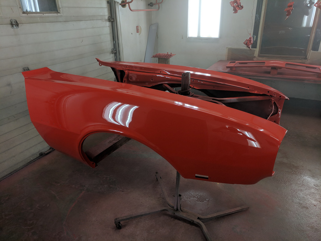
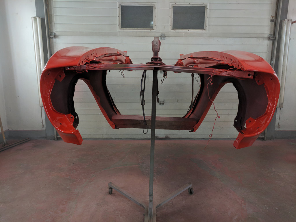
Then I laid down two color coats on all of the panels.
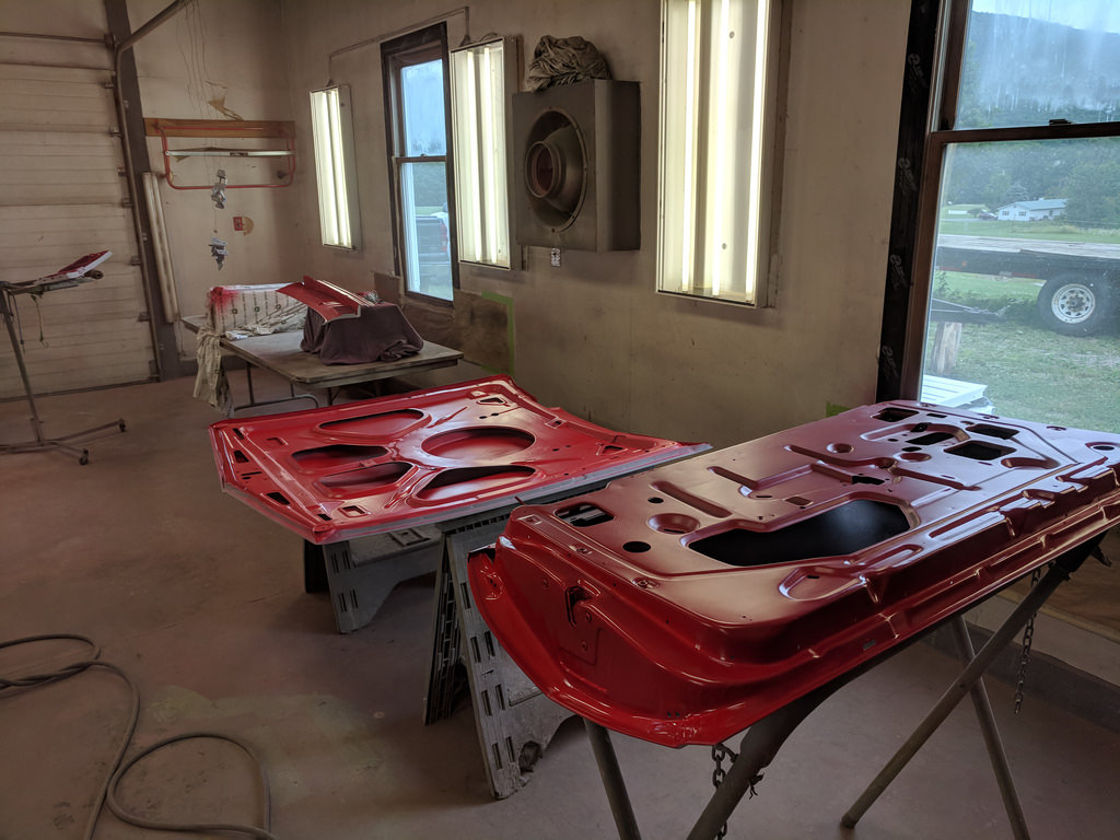
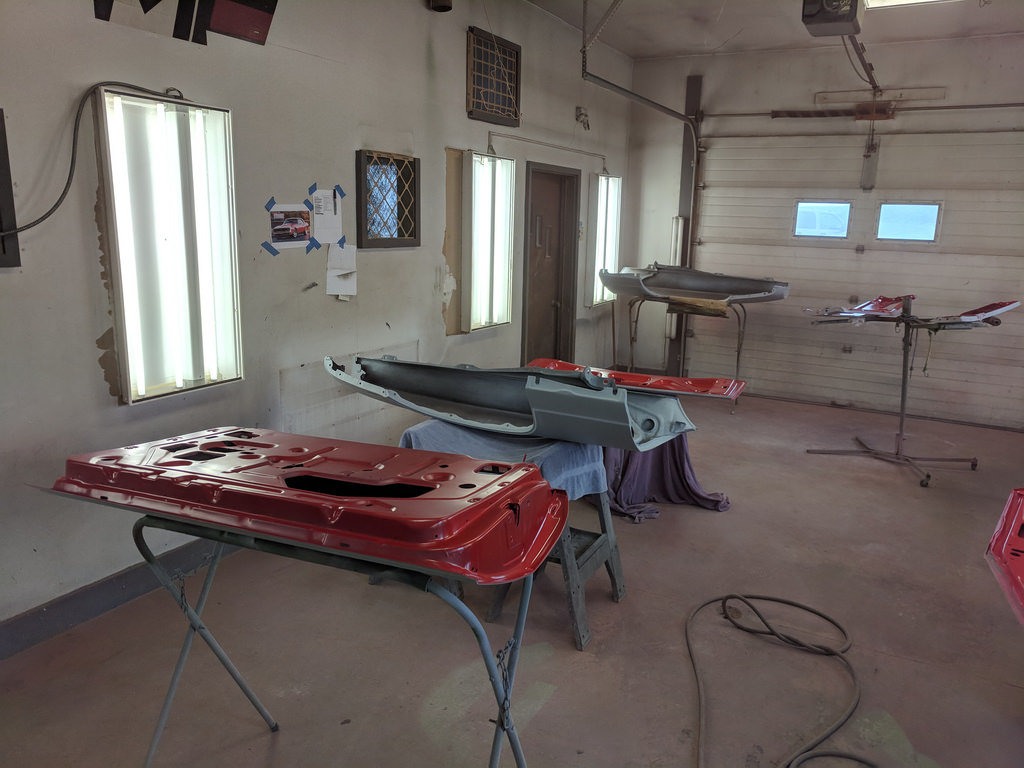
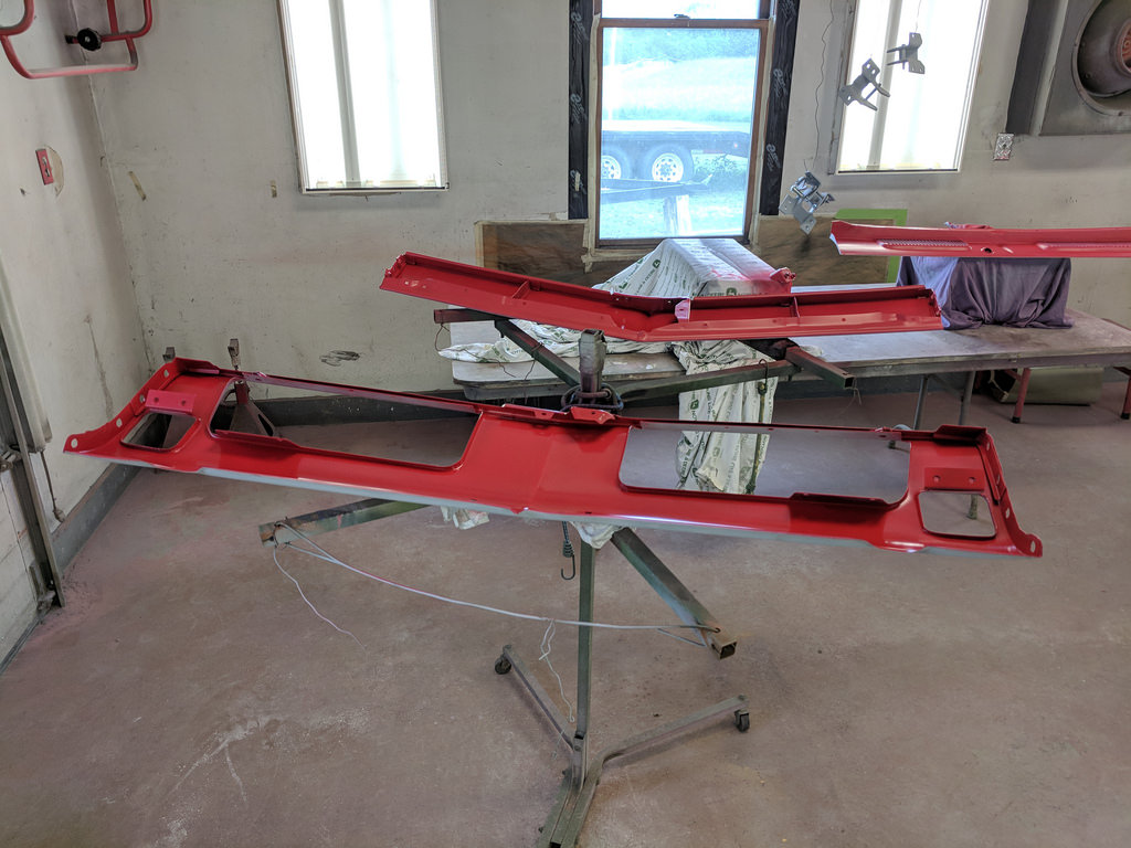
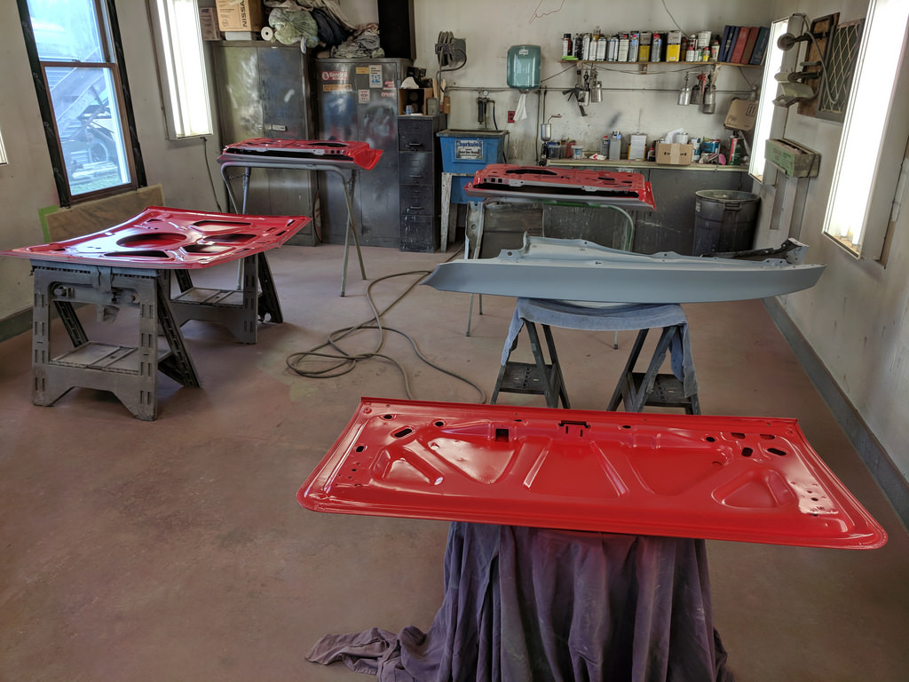
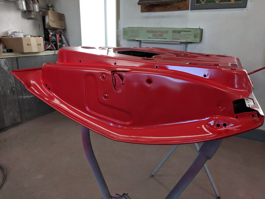
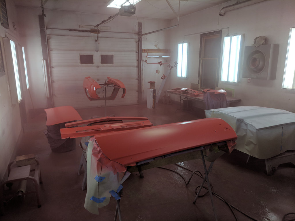
I had sprayed a few color coats on the shell, but I hadn't sprayed any clear. I had watched my buddy do it and he gave me some pointers before I started and I was very pleased with the results after 1 coat of clear.
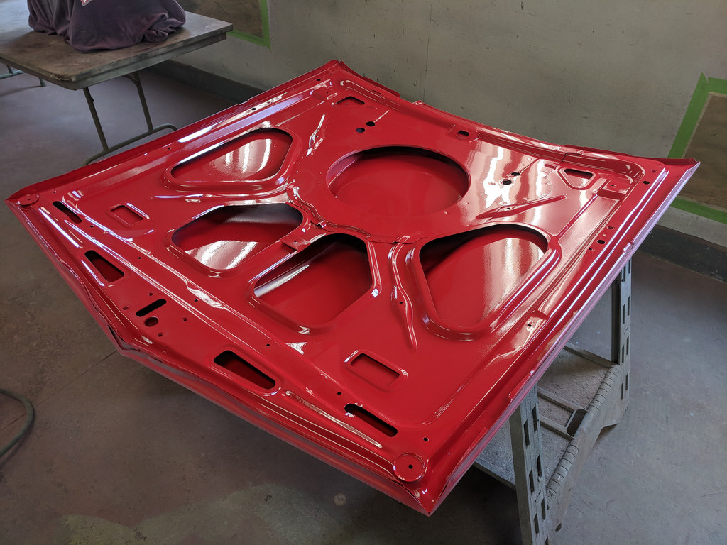
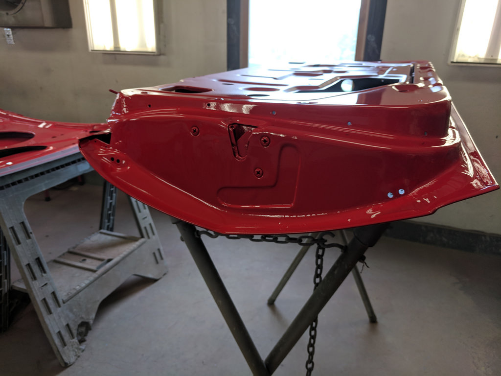
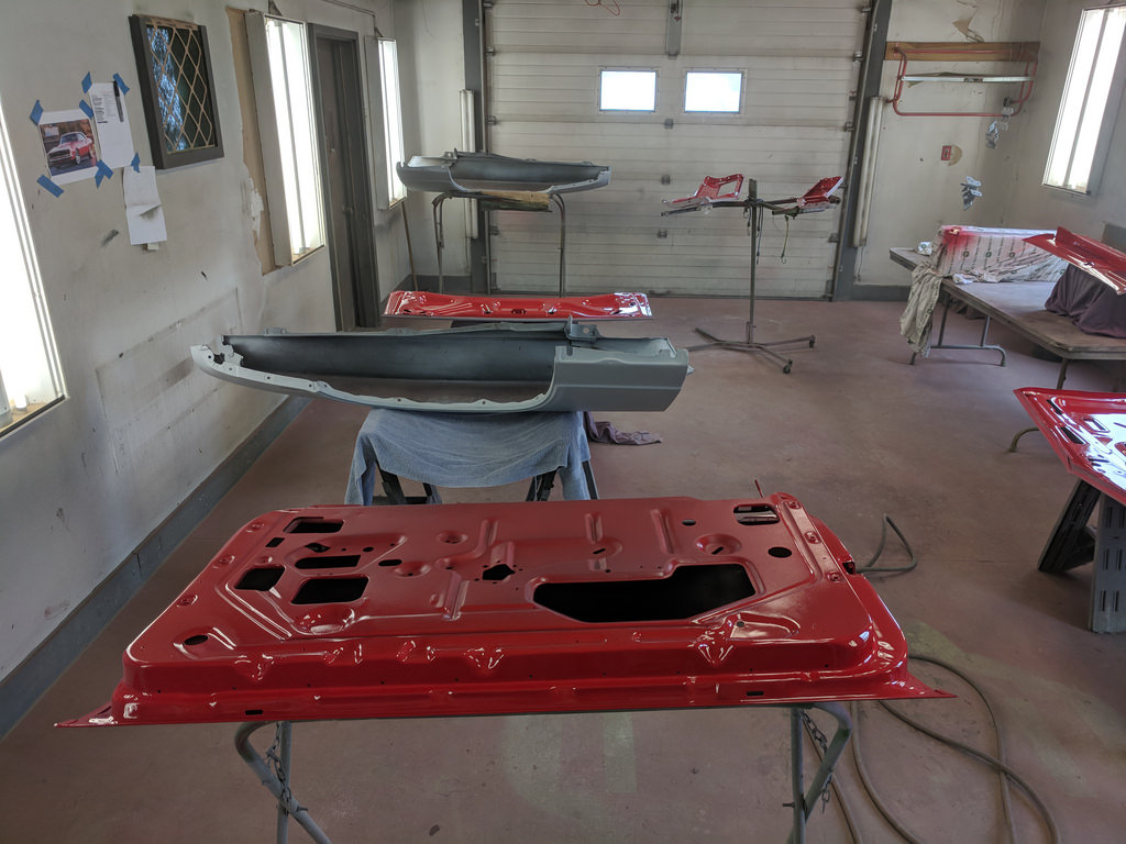
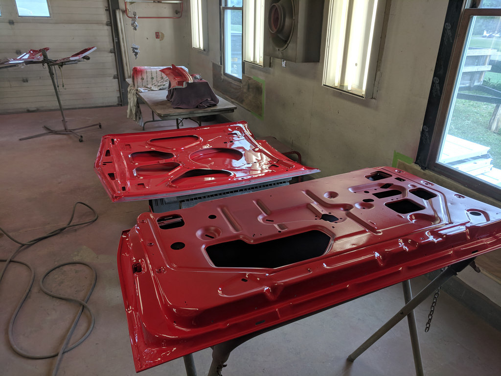
The 2nd coat really brought out the shine!
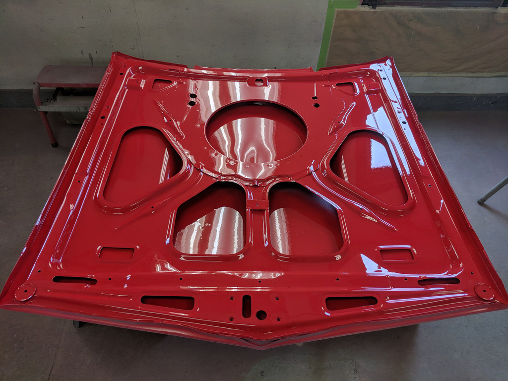

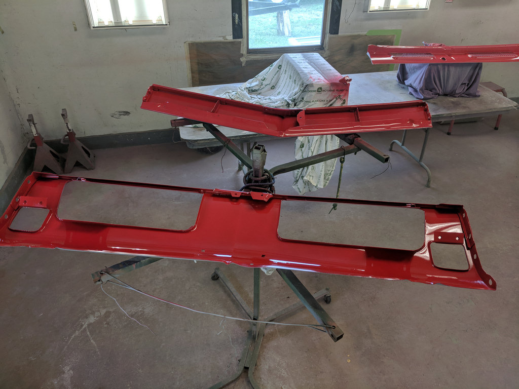
Very happy with the way that everything turned out. I definitely built up my confidence spraying these panels. Hoping to get my frame welded back up this week and put the motor and trans back together. Won't be too much longer and I will be bolting these panels back onto the car!
Cheers,
Ryan
1955 Nomad project LC9, 4L80e, C5 brakes, Vision wheels
1968 Camaro 6.2 w/ LSA, TR6060-Magnum hybrid and etc SOLD
1976 T/A LS1 6 Speed, and etc. SOLD
Follow me on Instagram: ryeguy2006a
-
06-26-2018 #365
 Registered User
- Join Date
- Dec 2008
- Location
- Detroit
- Posts
- 2,585
My hats off to you! That's a great job for a beginner. It's got to feel good having done it yourself....
Big dreams, small pockets....
Chris--
'72 Cutlass S LSA/T56 Magnum
Bowler Performance, Rushforth Wheels, ATS, Holley EFI, KORE3, Ridetech
Project Motor City Madness
-
06-27-2018 #366
Registered User
- Join Date
- Nov 2010
- Location
- Ventura County CA
- Posts
- 556
I don't mind at all. I'll try to remember to do that tonight and take some photos best I can. It's a lot harder to get into that area now that the car is all together which is why I recommend figuring this out now while you have full access. Originally Posted by ryeguy2006a
All the fresh painted panels sure look great! Those complex surfaces, nooks and and curves are such a challenge to get full coverage on without either missing areas altogether or putting too much on and causing runs. It's going to be such a nice car when you get it back together!Clint - '70 Nova "restomod" cruiser & autocross family car
-
07-02-2018 #367
Registered User
- Join Date
- Sep 2009
- Posts
- 2,707
I had a long weekend and got a lot done on this car. We took off this past Friday to go to a concert in Camden, NJ to see Chris Stapleton and since we weren't leaving until 9am on Friday, I knew I could stay up a little later and get some work done on the old Camaro. Fantastic concert by the way, what a truly talented performer.
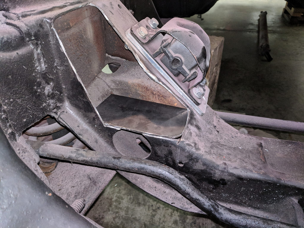
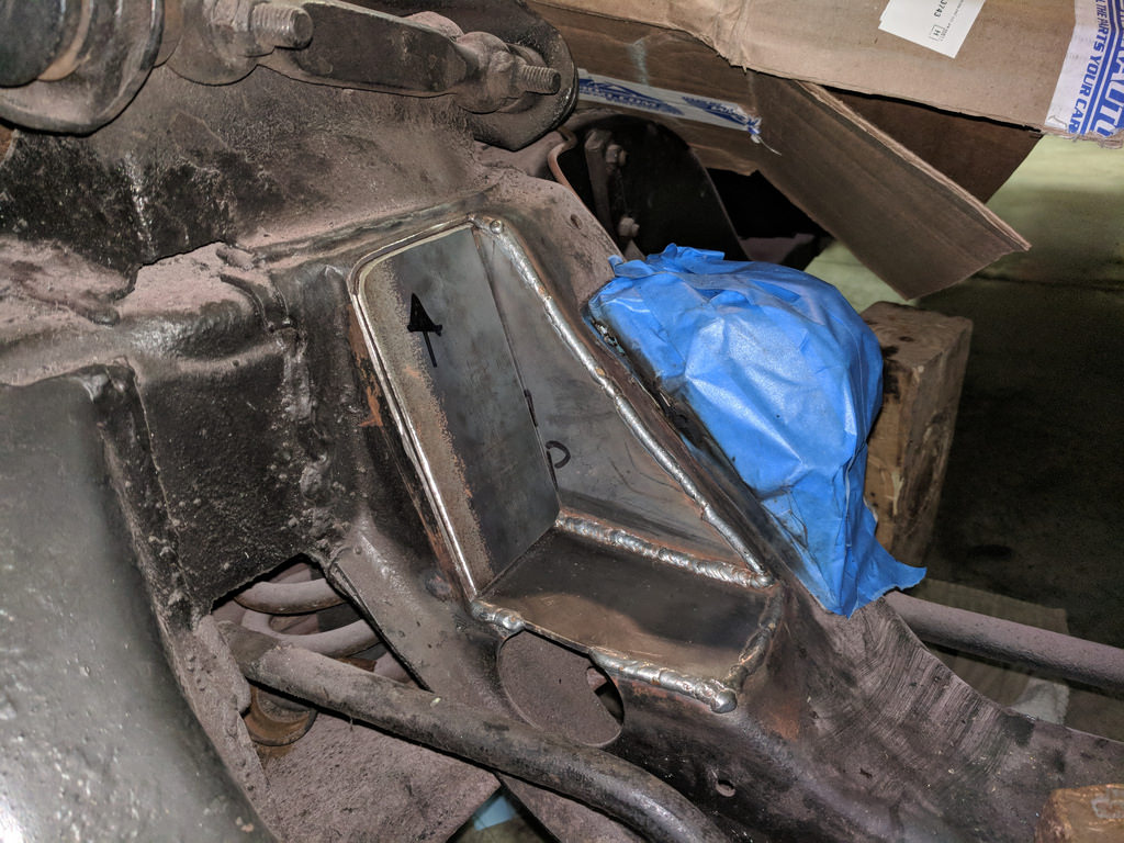
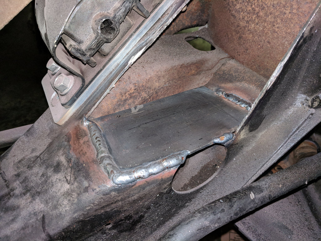
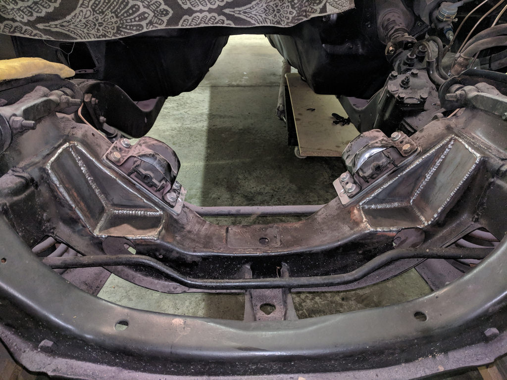
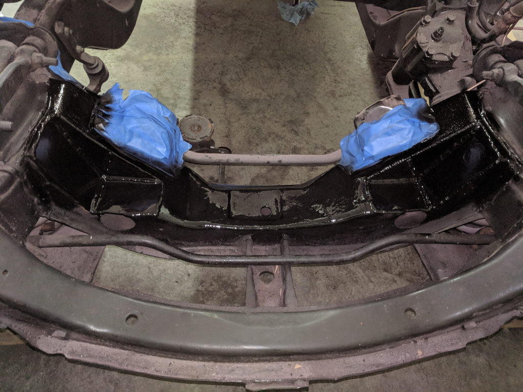
My focus has been to get the frame notches done so that I can get the motor back in the car. I decided to make the plates in three pieces for a few reasons. One was that I would be able to tie in the plates to the outer frame to give it a little more strength, and two was that the plate I bought was a little on the thick side and would be difficult to bend. It took me a while to get into a groove with the cutting and fitting but once I did it went pretty quickly. I started by using a cardboard template for every plate, and carefully cut out the shapes with a thin cutoff wheel on my angle grinder.
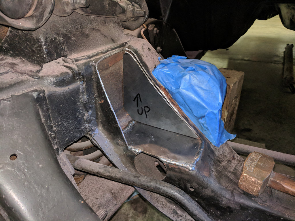
Not the best welds in that pocket, but there must have been some sort of contamination. I made sure to wipe down all of the surfaces with denatured alcohol, but I guess it didn't matter in this case.
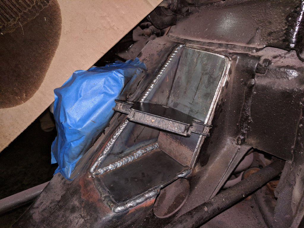
Good thing is the bad looking welds were hidden by this piece.
I'm very pleased with how it turned out. The welds are a little cold but it was all that my little Miller 135 could handle. It still had solid penetration and the area isn't a critical structural component so I'm confident it will be fine.
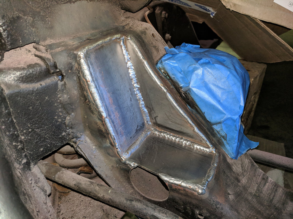
That's going to give me lots of clearance for my low mount AC Compressor when the time comes to reinstall. I'll be very glad I planned ahead when I go to install Vintage Air in the future. I still need to figure out how to make that compressor and the sway bar live happily together, but at least the pump will bolt to the engine and clear the frame. I'm hoping that was the hard part.
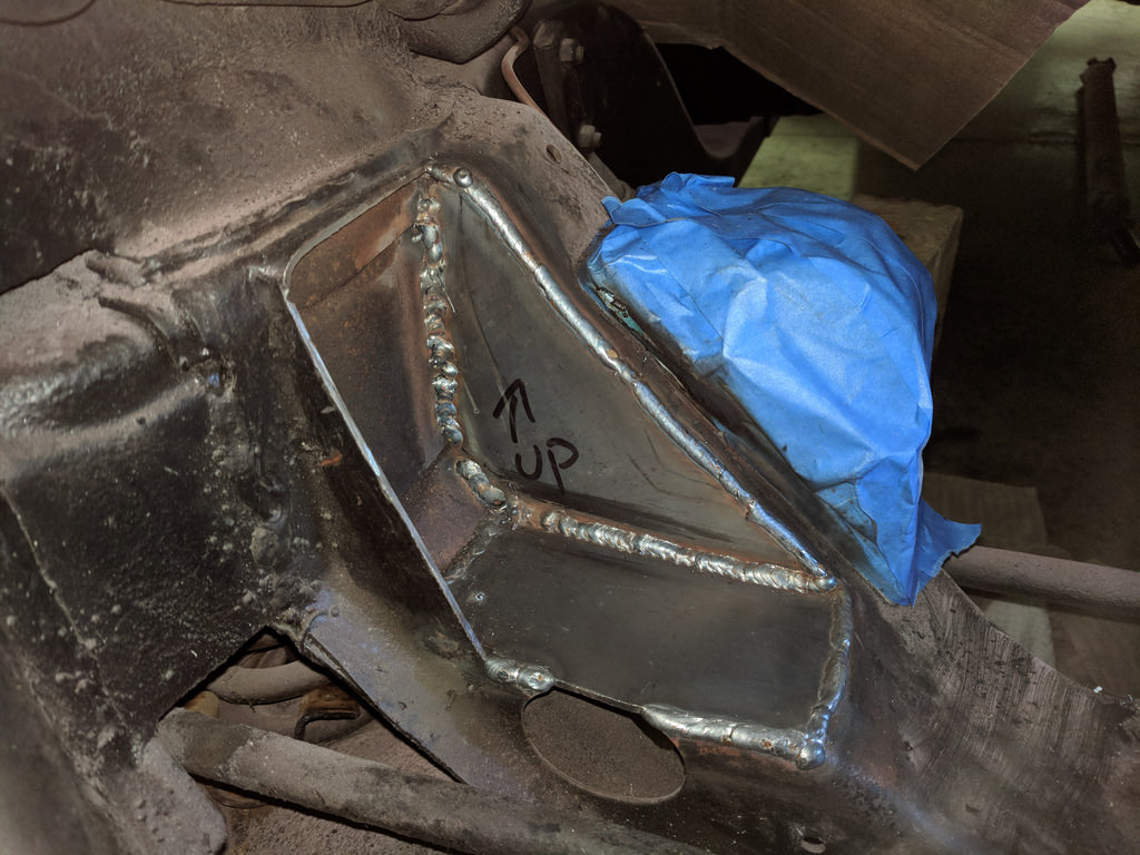
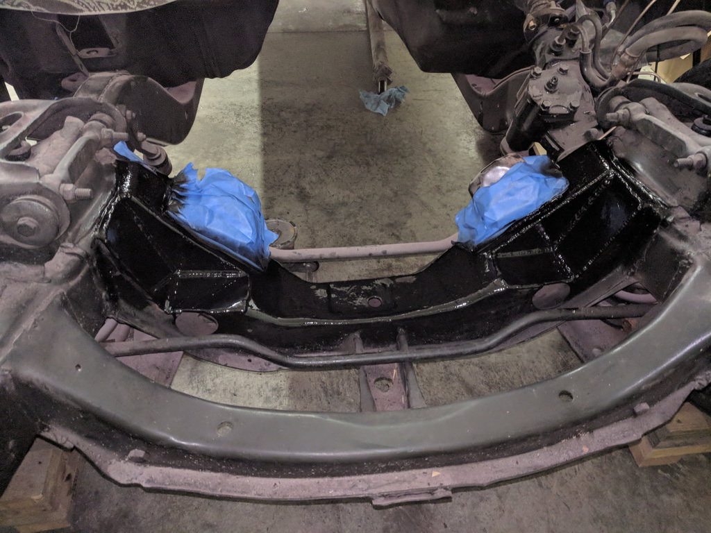
Then I had to repeat the same process on the driver's side.

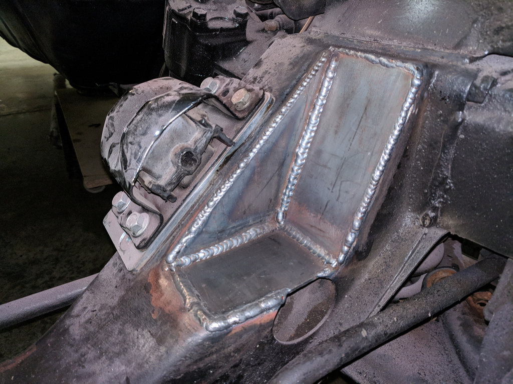
Both sides turned out great. I was very happy with the results. I'm happy enough with the welds that I'm going to leave them exposed and just paint over them. All notched and ready for a drivetrain once it's painted!
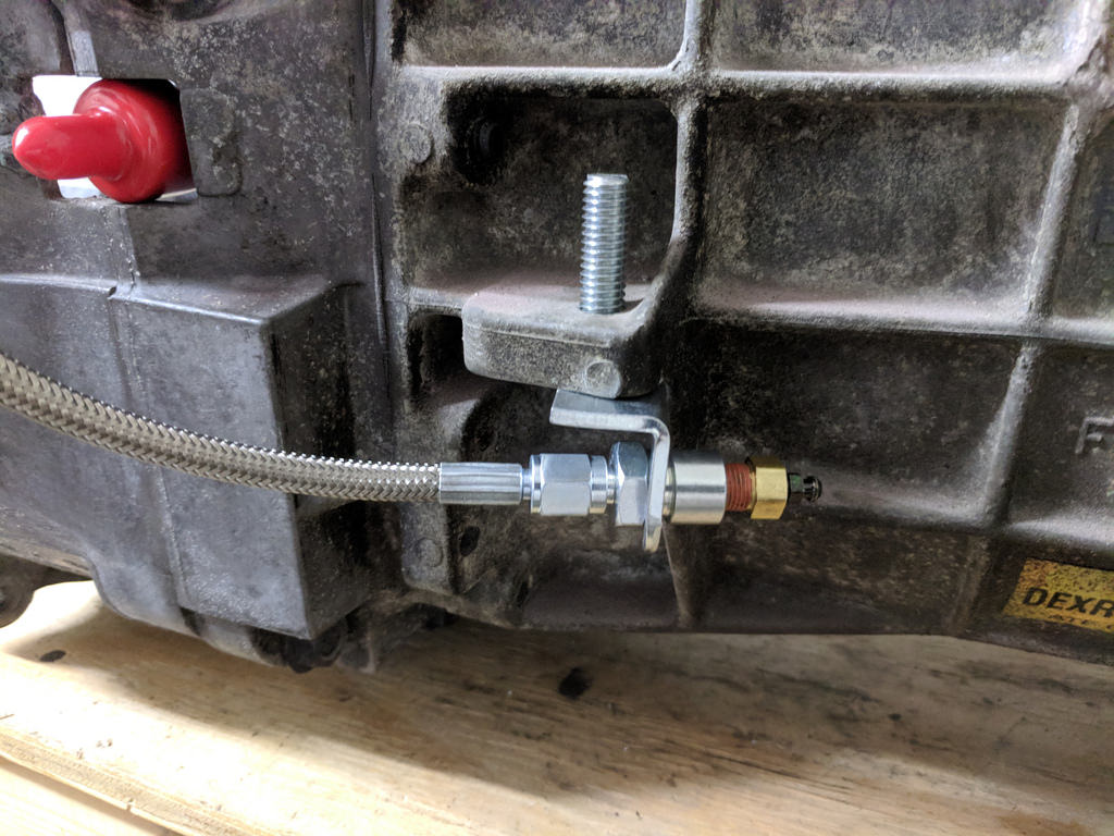
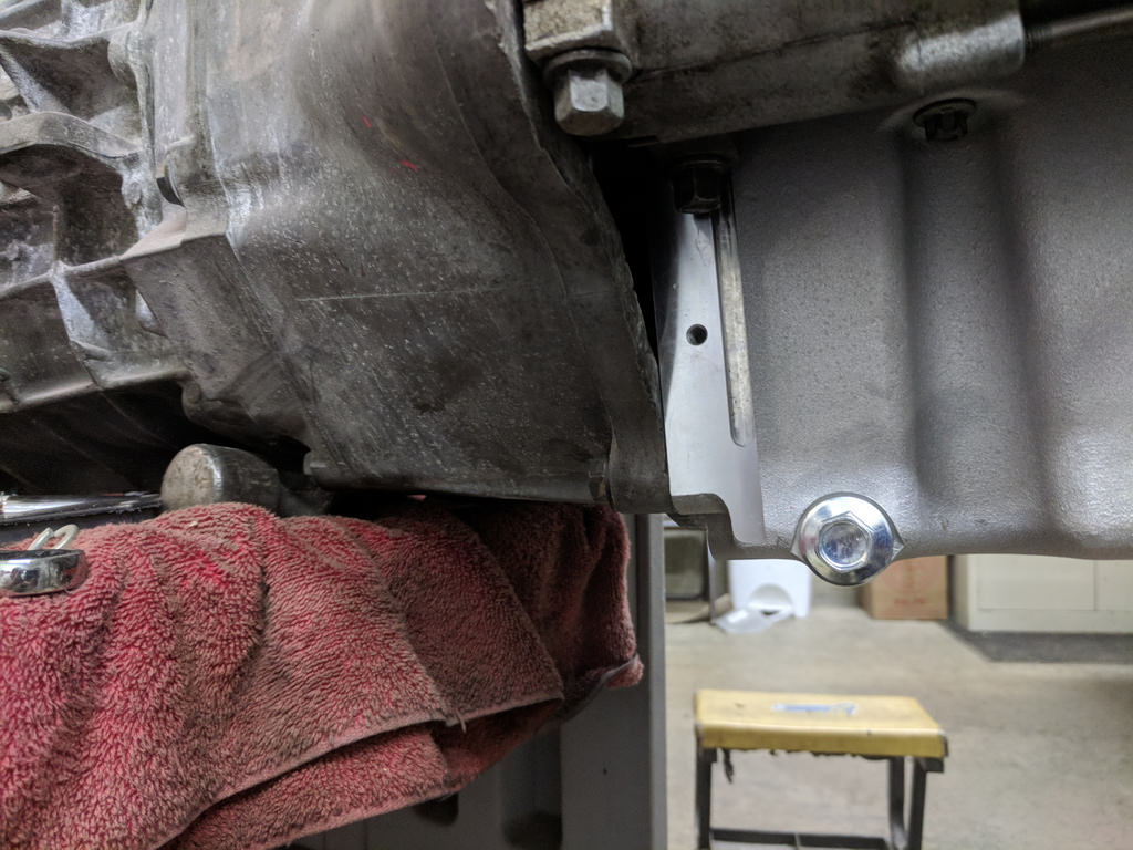
A good habit that anyone doing fabrication and heavy welding/grinding should get into is letting everything sit to make sure there isn't a smoldering fire. I've heard of too many stories where people get done welding/grinding and shut down the shops/garages and something was on fire, but couldn't tell right away. I always wait at least an hour and check for smoke or smells. So to keep me busy I took on a few other secondary tasks to get the drivetrain back in the car. First was finding a mount for the remote bleeder. I tapped this boss on the side of the trans and used an extra brake tab. Worked like a charm and fits great. For anyone wondering, I got the Speedway remote bleeder in 12" length. Installed with the new slave cylinder/throw out bearing from Luk.
Just need to get a shorter bolt and I'll be in business.
The next task was doing a final install on the Holley 302-3 oil pan. I was very impressed upon the first trial fitment and didn't really appreciate it as much because I was more focused on the initial frame notches I did. I modified the full length windage tray that came with my motor, which was very simple using the provided instructions. I did that last week, and now it's ready to install.
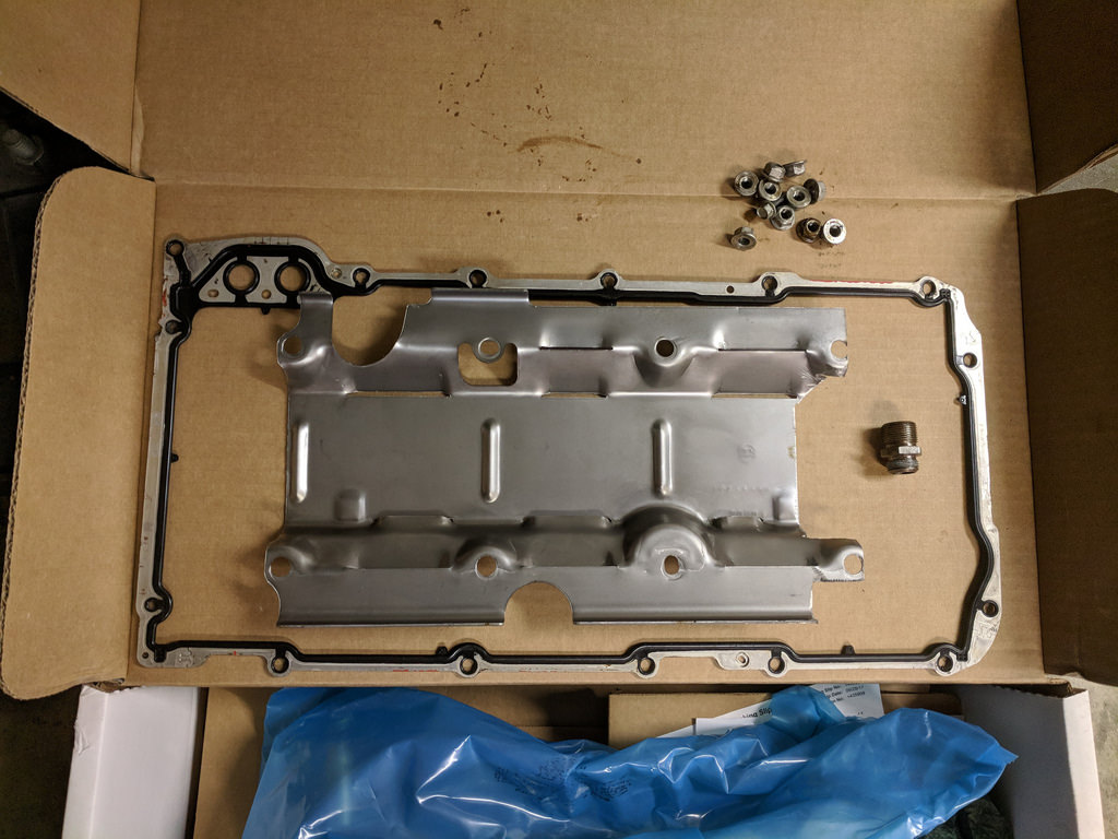
I torqued everything down using the existing hardware and also test fit the oil pump pickup. As I was inspecting the pickup I noticed that Holley went to the extra step of adding a flange with two bolts instead of one like the stock one.
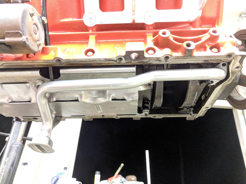
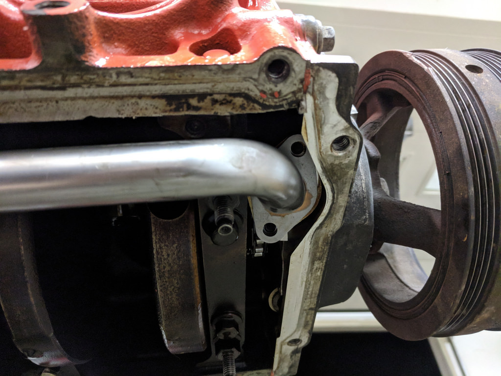
I got to the point of test fitting the pan with the windage tray and pickup, but couldn't final install as I was missing some RTV sealant. I pulled the plugs and spun the motor around and didn't hear any strange noises. I'm confident there will be no issues.
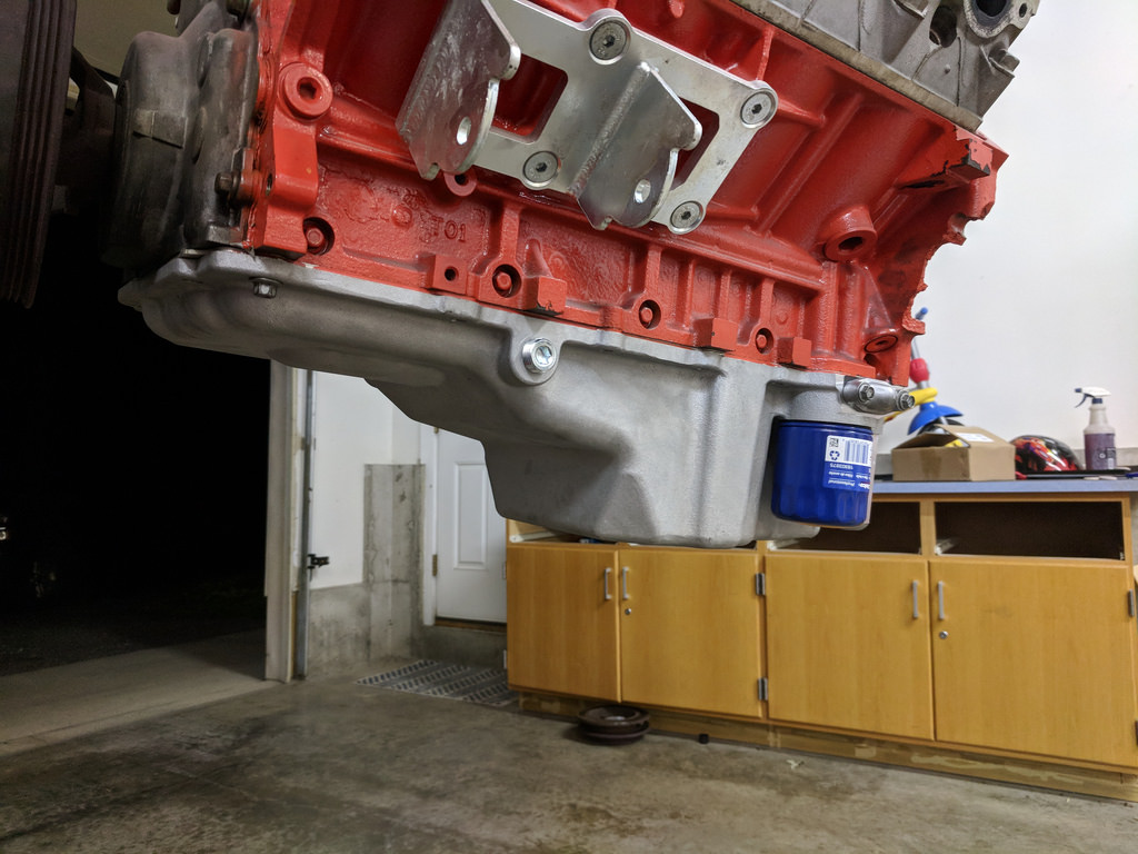
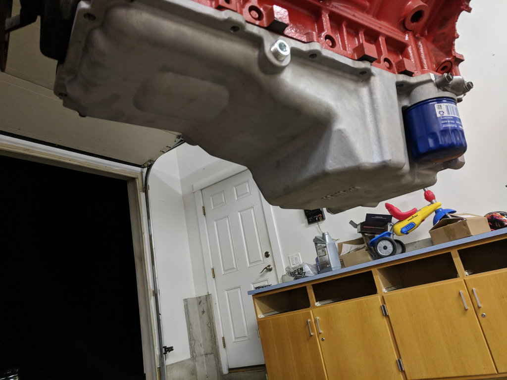
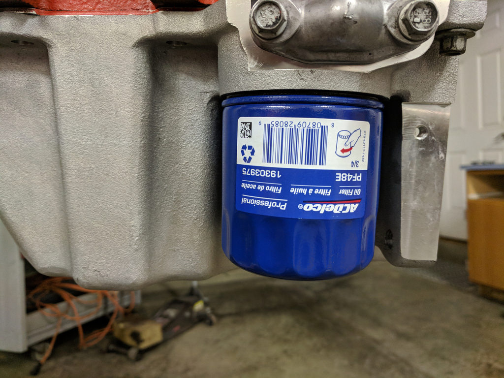
And topped it off with a brand new AC Delco oil filter. I used the part number that the instructions listed, PF48E
Overall very happy with the progress from this weekend. It is a huge relief knowing that the fabrication is now done and it's basically just need to bolt stuff on now. This next week and weekend is going to be busy with my son's Birthday party and the 4th of July. I'm hoping to sneak some time here and there to get the oil pan buttoned up, clutch installed and the motor/trans reinstalled.
Cheers,
Ryan
1955 Nomad project LC9, 4L80e, C5 brakes, Vision wheels
1968 Camaro 6.2 w/ LSA, TR6060-Magnum hybrid and etc SOLD
1976 T/A LS1 6 Speed, and etc. SOLD
Follow me on Instagram: ryeguy2006a
-
07-09-2018 #368
Registered User
- Join Date
- Sep 2009
- Posts
- 2,707
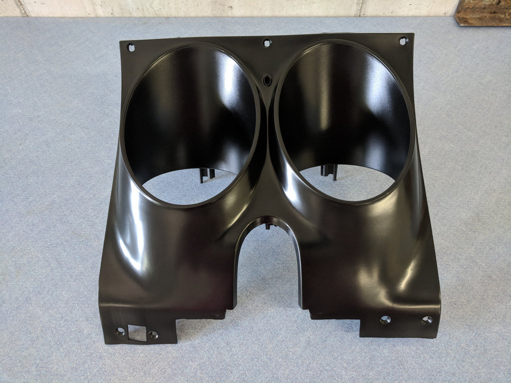
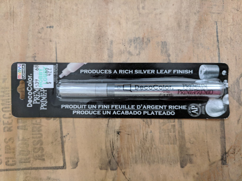
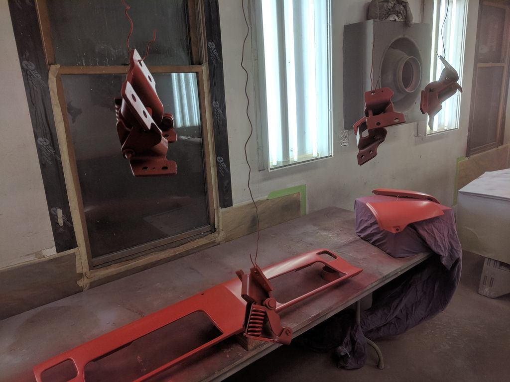
I was able to get a fair amount of work done this week here and there. This post is very scattered, but I'll try to make it easy to follow. Whenever I have a few minutes between mowing, or other chores after work I try to get a little something done during the week. I'll start off with the gauge housing that I refinished. I scuffed it up with a red scotch brite pad and shot it with the same dash paint. It turned out great and is an exact match for my dash. Once it drys for a week or so, I'm going to use this silver leafing pen I picked up. I have read on other forums where this particular pen makes it look just like stock. I hope to try it sometime this week.
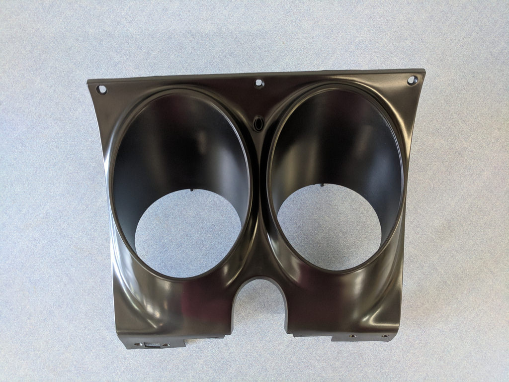
[
I spent several hours working at my buddies house getting the rest of the body panels closer to paint, but it was so incredibly hot in his paint booth we opted not to spray in fear it would turn out bad. So I ended up coming home and getting the drivetrain back together. First thing I did was finalized the install of the Holley oil pan. I dabbed the black silicone on the four corners of the front and rear covers and sealed it all up. To ensure that the oil pan was aligned with the bellhousing I bolted the trans to the motor and snugged the bolts down hand tight. Then I torqued the oil pan bolts.
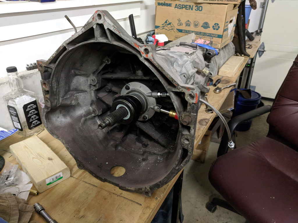
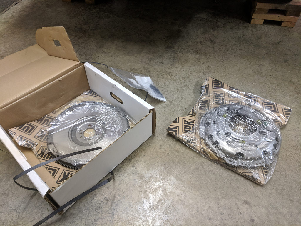
Then it was time for the brand new LS7 clutch. It might be helpful to others, but this is the same clutch that you would get from GM Performance. LUK is the factory supplier to GM, and this is their complete LS7 replacement clutch kit part number 04905. It came with a new pilot bearing, pressure plate bolts, clutch, flywheel and pressure plate. At the very reasonable price of $220 from Rock Auto. Although I re-used the ARP flywheel and pressure plate bolts.
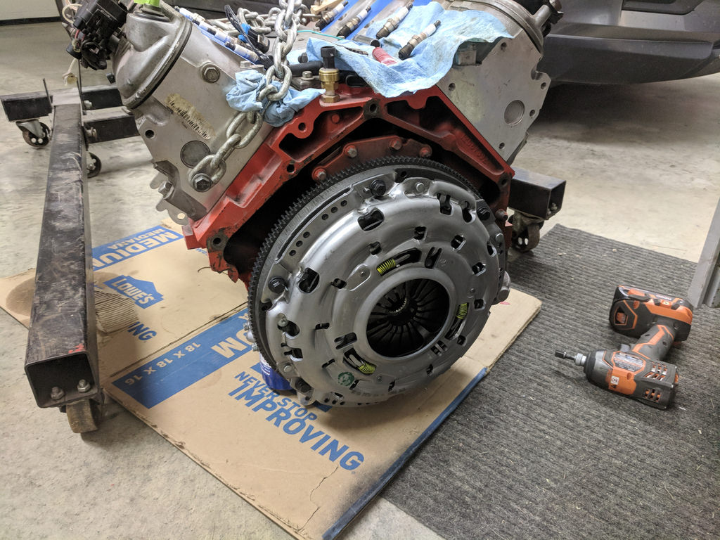
Then it went back together with the trans for hopefully the last time.
I also wanted to get some paint on the notches so that I could reinstall the motor now that the drivetrain is back together. I used the same paint as I did before on the frame, but for some reason it was much glossier. Hopefully it will not be as noticeable once all the components start getting bolted back on.
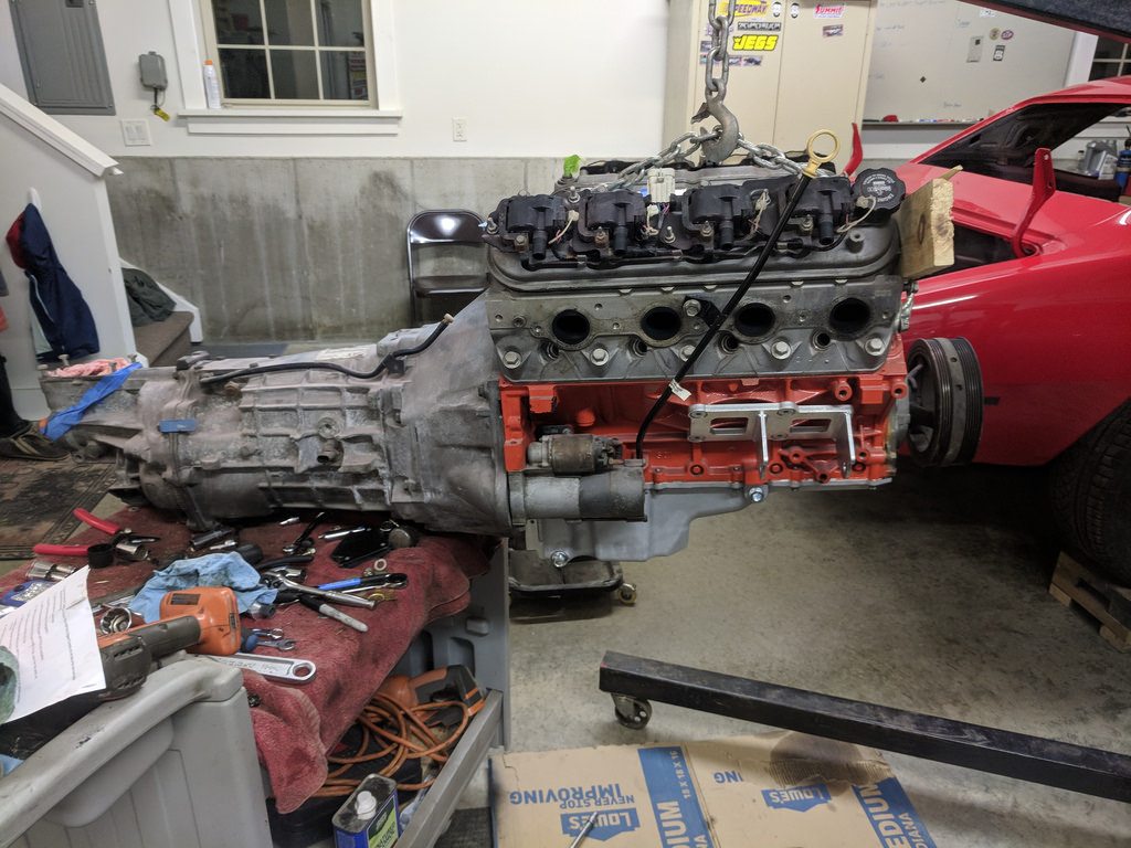
Then Saturday when everyone was napping, I decided it was time to put that motor back in! I've had it in now so many times that it really didn't take me long at all. About 45 mins and it was bolted down. It went in flawlessly. Before I can call it good I still need to confirm that I have solid oil pressure. I'm 99.9% sure that it is fine, but I've seen where people go to install the oil pickup and the o-rings get pinched.
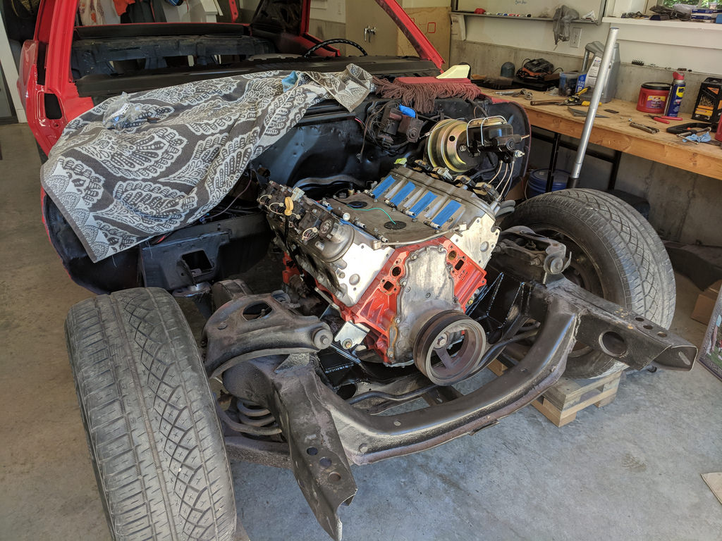
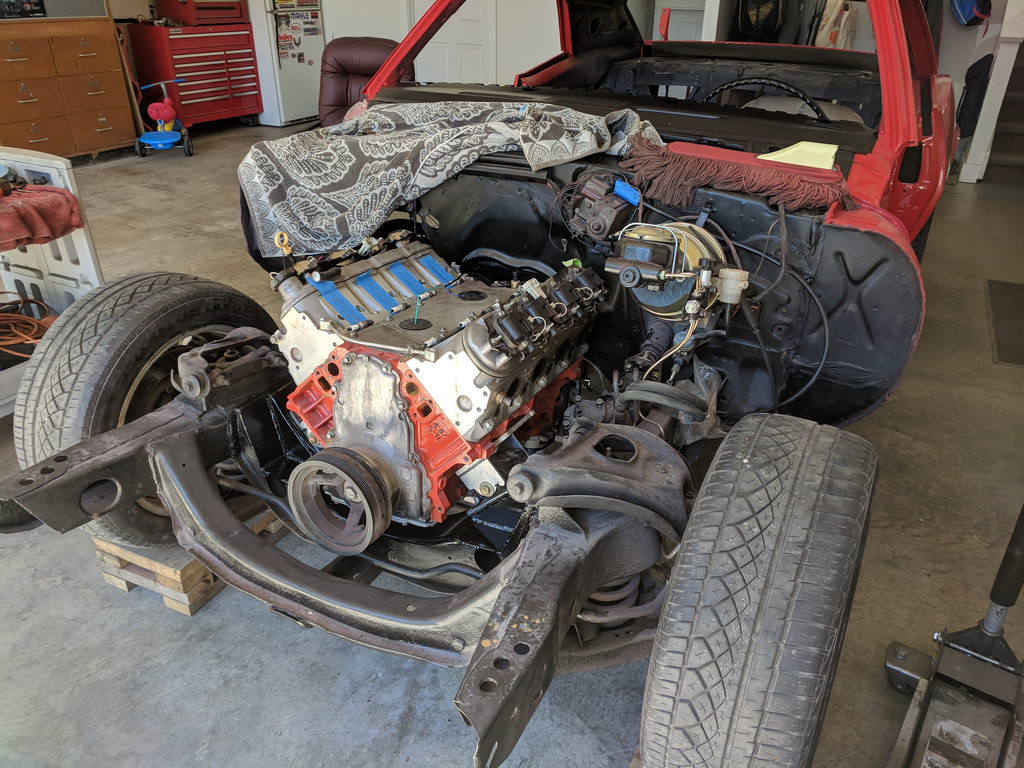
All ready to mount some accessories down low. That was a lot of extra work, but glad that it's over with. Now, I have plenty of room for everything and will make for a clean install.
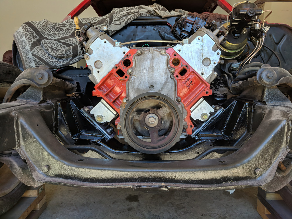
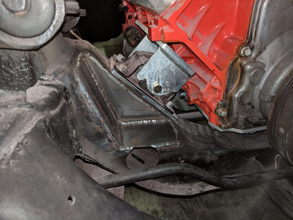
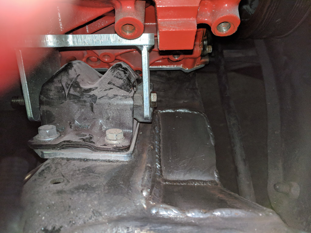
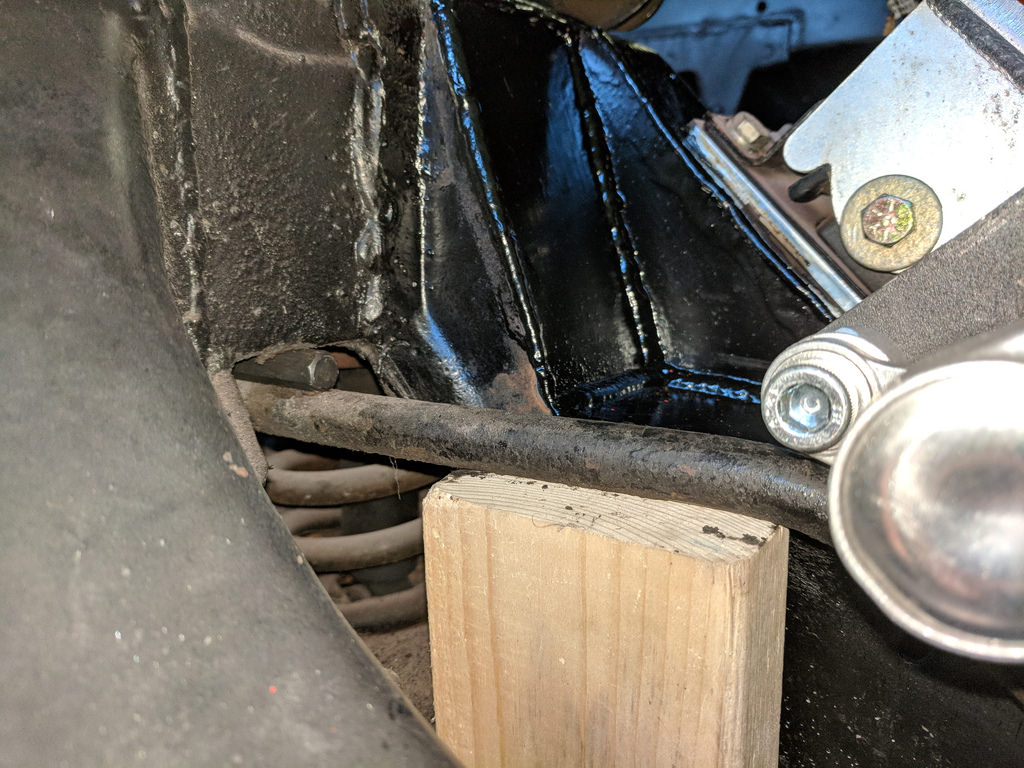
After getting some feedback from others, I've decided to go ahead and modify the brackets for my low mount A/C compressor now rather than later. I have full access to the front of the motor right now and it would be much more difficult to get to it later. Now that I have the Dirty Dingo brackets mounted with the sway bar bolted in place and the new oil pan, it is clear that they aren't all going to play together. Mostly a sway bar issue at this point, but the biggest thing is the compressor physically fits with my motor mounts and frame with notch. After some measurements and playing around with the placement of the compressor, I can modify the mounts slightly to work for my situation. First thing was to take some measurements of where the sway bar is in relation to the compressor.
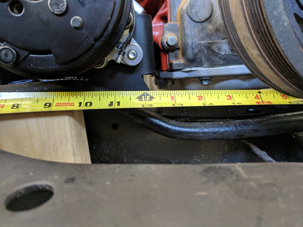
Then I could play around and see if I could make the heights of the sway bar work with these mounts. I trimmed a little off of the edges near the motor mounts and found that if I could raise the lower mount up by ~2" and add a 1/2" spacer to the swap bar mount that I would have roughly 1/4" between the sway bar and tensioner. Win!
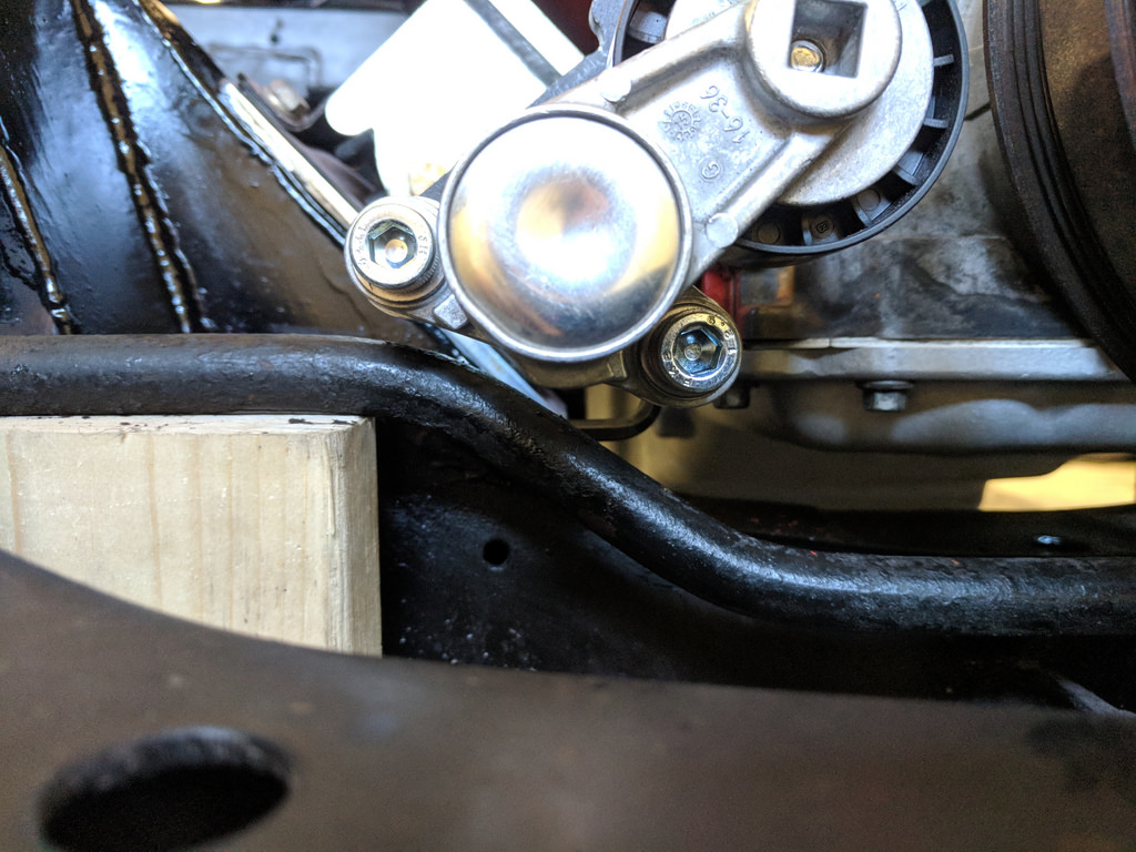
This is a punch that I found that was exactly 1/2". I also figured that I would use the swaybar butt right against the 1/2" spacer to simulate if I was to get a larger diameter sway bar as it would sit much tighter to the frame. I'm at least trying to future proof it.
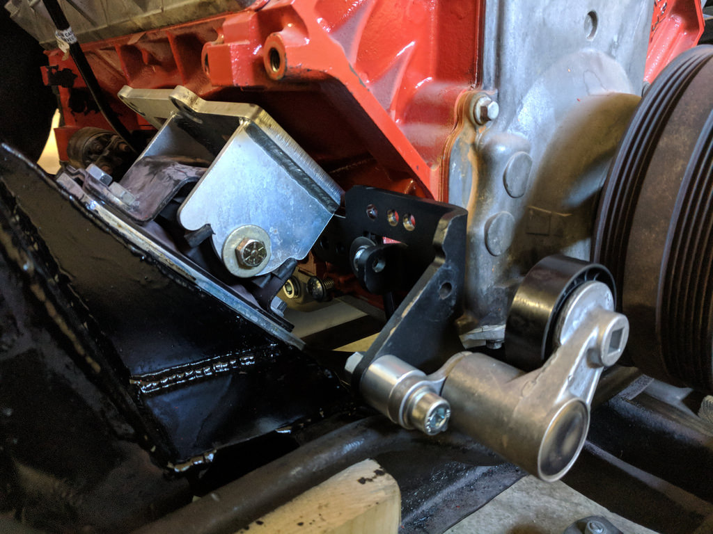
Here is where the mount roughly needs to be in order to keep the original geometry of the mount, but in a raised position. Now, you may notice that the mount is actually causing the compressor to move more forward than the stock position. This is because the original mounting position uses the trucks 4 rib pulley to the outer edge of the pulley on the Sanden compressor. My thought is since I'm modifying the bracket anyway I'm going to move the compressor 2 ribs (~.300")forward to give me a little more clearance around the motor mounts.
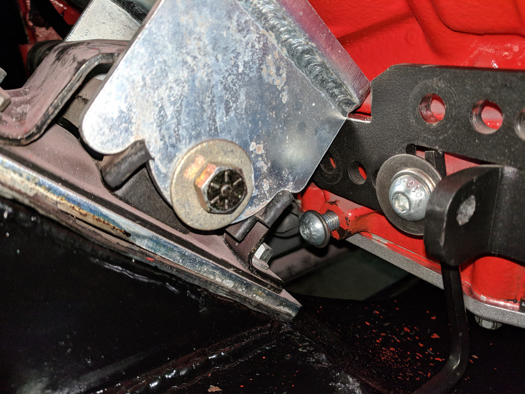
My plan is to cut an L shaped piece of 1/4" plate and weld it to the lower side of this bracket to raise the mounts to where I need them. Once the lower mount is finalized and mounts the belt flush with the pulley, I'll address the upper mount. Which I believe will be easier as it should either be a spacer to match, or extending the arms out slightly.
Cheers,
Ryan
1955 Nomad project LC9, 4L80e, C5 brakes, Vision wheels
1968 Camaro 6.2 w/ LSA, TR6060-Magnum hybrid and etc SOLD
1976 T/A LS1 6 Speed, and etc. SOLD
Follow me on Instagram: ryeguy2006a
-
07-09-2018 #369
 Registered User
- Join Date
- Aug 2015
- Location
- charlotte
- Posts
- 924
Good progress. I'd love to hear your feedback on the LS7 clutch when you finally get her up and running, I'm considering the same one
-
07-10-2018 #370
Registered User
- Join Date
- Jun 2015
- Posts
- 171

um since when was a cars crossmember not a critical structual component?135 amp mig welder barely has the power to weld 3mm plate let alone cold welds on unpreped rusty steel, hopefully you are running driveshaft loop so when it lets go it doesnt damage any "critical structual components"its good to be half a world away because i would not like to be sharing a road with this project.
-
07-10-2018 #371
Registered User
- Join Date
- Sep 2009
- Posts
- 2,707
GMC427, I should clarify. What I meant was the part of the small crossmember sections that I removed didn't critically affect the stability of the frame. For the record, I wouldn't be putting anything on the road that wasn't safe. All the welds were beveled and pre-heated where necessary for solid penetration. The welds were slightly cold as I hit the limits of my machine, but far from unsafe. The frame is at least as structurally sound now as it was before I made the cuts. I appreciate your input though for the clarification.
1955 Nomad project LC9, 4L80e, C5 brakes, Vision wheels
1968 Camaro 6.2 w/ LSA, TR6060-Magnum hybrid and etc SOLD
1976 T/A LS1 6 Speed, and etc. SOLD
Follow me on Instagram: ryeguy2006a
-
07-10-2018 #372
 Registered User
- Join Date
- Mar 2013
- Location
- Napier, New Zealand
- Posts
- 220
Hey mate, i highly dout very much "The frame is at least as structurally sound now as it was before I made the cuts". You have significantly reduced the strength of your chassis main crossmember. Strength comes from "beam width" and you have removed over half of this on each side. Your engine mounts carry the maximum load down and your upper A-arm mounts and spring mount apply maximum load up. You have created a weakened point at the "bending moment" of the chassis critical structure area. I would be cad modelling this to access a FEA test. Originally Posted by ryeguy2006a
My question is "WHY" there must have been thousands of LS motors in 1st gen camaro's, mine included and I have never seen the need to do this?
This modification would be illegal in nearly every other country other than usa. just saying.Damien
Napier, New Zealand
Project Page: https://www.pro-touring.com/showthread.php?99096-Project-Camaro-68-P-T-Muscle
Next Project: 1956 Chevy Truck, Full C3 Suspension, Nascar Inspired
-
07-10-2018 #373
Registered User
- Join Date
- Nov 2010
- Location
- Ventura County CA
- Posts
- 556
I'll chime in here not because I'm 100% qualified or have all the answers or even consider myself to be "right", but I am a mechanical engineer and I did a very similar modification on my Nova's subframe which I have put through a few paces street driving and autocross. I can't tell you for sure this modification is safe and although I am an engineer I haven't done any sort of deep analysis on this subject, so take my input for what it's worth
First I'll address the design of this notch and second the execution since they both are relevant with regards to the end result/strength.
From a design perspective, if you look at the original frame crossmember design it is a contoured section with a large "dent" (for lack of better terms) in this area added for accessory clearance. The inside is relatively open and it acts as a fairly large box section. The lower control arm mount is frenched into the bottom plate but has no direct support above it (you can see this in ryeguy's photos prior to welding in his new plates). I remember measuring the material thickness and if I recall it is something around 0.150in thick. ryeguy and I have essentially cut out the contoured "dent" area and replaced it with a combination of a lower-positioned flat plate connecting the bottom, a rear plate which boxes in the area under the motor mount and connects it to the lower control arm mount, and a side plate that re-establishes the "upper" section of the crossmember. In my opinion, the result of this redesign has some competing factors with regards to overall strength. For example, the rear plate boxing the section between the lower control arm mount, motor mount, and frame rail potentially increased the bending strength and established a load path between the lower control arm mount and the frame rail that didn't exist before. I think that boxing that area may actually be an improvement from the perspective of supporting the engine and the loads from the control arm. On the other hand the overall cross section has somewhat shrunk in the area of the pocket and that may have some impact to both bending strength and torisonal strength (which I think is less of a concern for this load member). This could certainly increase the stress in some areas of the frame. Additionally the new load path for that vertical plate is stiffer than before so it will try to share more of the load than it used to which may or may not be a problem. And of course the sharp transitions at the edges of plates can act as load concentrations. Is it as strong as it was originally? I'd say probably not. But looking at the overall structure of the modified frame, it still appears to be more robust than a number of OE single crossmember subframes (i.e. 2nd gen Camaro) and aftermarket tubular frames, both of which have proven to be robust. In my personal OPINION and based on comparisons with other types of frames I've seen on similar weight vehicles the strength of this frame notch design should still be more than adequate for the task.
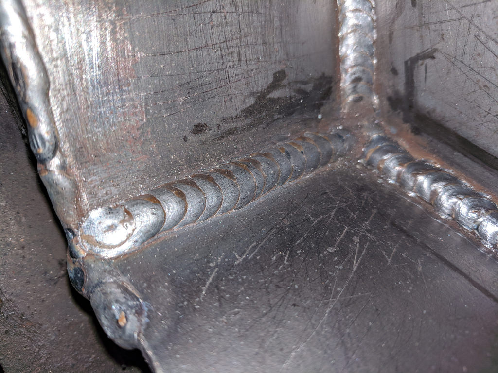
Now from an execution perspective looking at the welds. I do consider these to be important welds, especially the ones used for the rear vertical plate which in my opinion has become part of the main load-bearing structure of the frame since it comprises the stiffest section that will take load from the control arm and the box section that will carry the bending loads from carrying the weight of the engine. Penetration is important as well as the right amount of fill. The welds look to me to be somewhat cold. I don't see any color in the metal that would indicate it got hot enough and the edges of the welds did not "wet out" into the base material. Some areas it looks like you did the welds as a series of spot welds instead of continuous, which may look pretty but allows the material to cool down between "tacks" which could explain the lack of wet-out on those. With a 110v MIG if you're not getting penetration at the highest setting, you really should preheat the metal or pick up a larger welder to do the job. That said although they didn't fully weld out, they aren't just sitting on top either - they appear to have some penetration. It does look like you didn't use a flap wheel or grinder to clean the original metal or the plate metal before welding, which can introduce porosity and internal defects in the weld you can't see. The vertical weld on the rear plate to the frame rail looks the worse of them and I'm guessing that was caused by burn-back of the wire. Vertical welds are a little trickier and I'm guessing you had some sputter and difficulty as you made that weld. I struggle with those myself. But it looks like you didn't have that problem so much on the plates you put over the outside. Overall I think the welds look okay, not great, but ok. I've seen worse hold. I've seen better fail. It just depends on how they are loaded.
I have been in your shoes and made similar welds where I wasn't 100% certain - sometimes I have ground them out and redone them, sometimes not. It depended on how bad I thought they were and what my assessment of the load was they needed to carry. I have also sought advice and I think you should get input from more people than just some keyboard jockey like me.
I really can't say for sure based on a series of photos whether or not those welds are adequate. My leaning is that even though they are imperfect, I think they are probably still okay because there is a lot of linear weld area to share the load. If it were mine I would probably leave them alone and move forward. But someone has highlighted this risk to you and you will have to make your own assessment. Ultimately you are accountable for your own safety, the safety of people you put in your car and the people that share the road with you.Clint - '70 Nova "restomod" cruiser & autocross family car
-
07-10-2018 #374
Registered User
- Join Date
- Mar 2013
- Location
- Napier, New Zealand
- Posts
- 220
Proper chassis welding
All good info Clint
You clearly have knowledge, but Im not sure on your belief that this is exceptible.
We will have to agree to disagree
Here is an image of how I strengthen my coil over mounts as the factory only designed this mount to take a shock absorber, not the total spring load.
This is what full penetration welding looks like. No one in the USA would be required to or consider doing this. Henry Ford once said quality means doing it right when no one is looking.
Words of wisdom in todays world
Damien
Napier, New Zealand
Project Page: https://www.pro-touring.com/showthread.php?99096-Project-Camaro-68-P-T-Muscle
Next Project: 1956 Chevy Truck, Full C3 Suspension, Nascar Inspired
-
07-11-2018 #375
Registered User
- Join Date
- Jun 2015
- Posts
- 171
sorry but if you are as safety consious as you say, have your welds done by a ticketed welder along with driveshaft welded and balanced by a pro.
-
07-11-2018 #376
Registered User
- Join Date
- Mar 2009
- Location
- Houston, TX
- Posts
- 1,192
No dog in this fight, but the welds on the frame notch look tons better than the original welds on the frame.
Tu Ho
Firebird V2-LS swap
-
07-11-2018 #377
 Registered User
- Join Date
- Apr 2015
- Location
- Burlington KY
- Posts
- 357
Looking good!! Btw Ive seen the frame notch on many of these sub frame cars but the guys with aftermarket frames dont need to.
"Racing is life. Everything else is just, waiting"
-
07-20-2018 #378
Registered User
- Join Date
- Sep 2009
- Posts
- 2,707
Thanks for all of the feedback regarding the frame notching. I had a buddy come over who is a welder/fabricator by trade and has taken several classes in welding to give me his opinion. He gave me the go ahead so I'm going to just keep the notches as is. Now that the motor is back in the car for good, it was time to turn my focus back to the body panels and getting them prepped for paint. Last week I went over and shot a final prime on most of the body panels and a first prime on the hood.
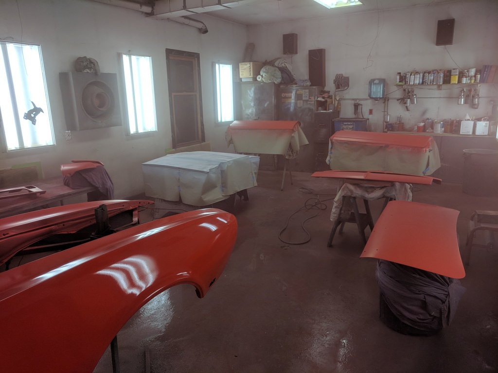
Then last night I came back to get some more work done. I started by spraying some guide coat and block sanding the hood with 220. It came out pretty good actually and should only need one more round of block sanding. Then I did a final sand, mask, and prep on everything but the hood and rear spoiler. After cleaning up the dust and wetting the floor I sprayed down a few coats of base.
This is after two coats of base coat.
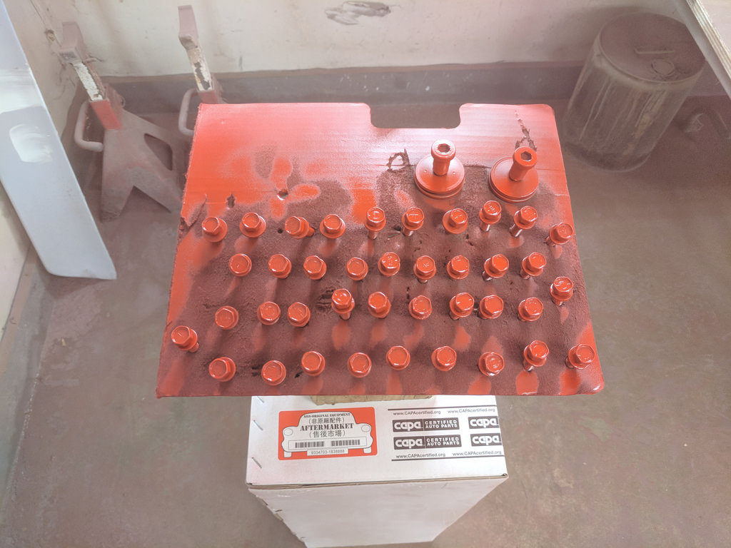
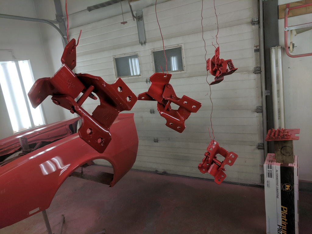
I sandblasted all these bolt and hinges, then sprayed etching primer and shot with the base coat.
Then three coats of clear.
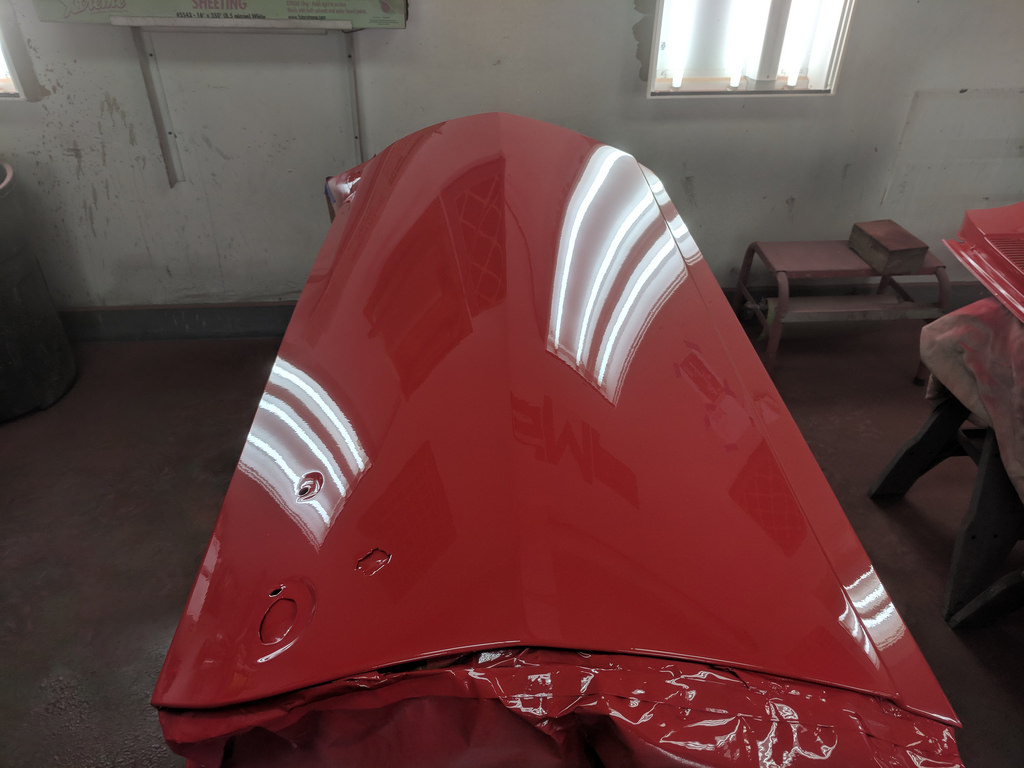
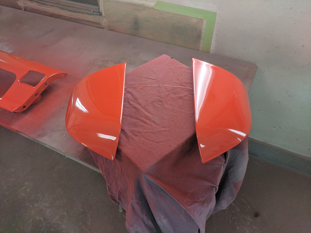
I can't wait for the RS Grill to go back in!
I'm very pleased with the results. I am going to stop by tonight after work and pick up some of the parts as my buddy needs his booth back. I'm hoping that I can possibly convince my dad or father in law to come over tonight and help me bolt up the doors. Can't wait to see the car come back together!
Cheers,
Ryan
1955 Nomad project LC9, 4L80e, C5 brakes, Vision wheels
1968 Camaro 6.2 w/ LSA, TR6060-Magnum hybrid and etc SOLD
1976 T/A LS1 6 Speed, and etc. SOLD
Follow me on Instagram: ryeguy2006a
-
07-20-2018 #379
 Registered User
- Join Date
- Sep 2004
- Location
- DFW, Texas
- Posts
- 217
Great work, love it!
My thoughts and ramblings while working on my motor driven menagerie http://mechanicdude.blogspot.com/
-
07-20-2018 #380
Registered User
- Join Date
- Aug 2014
- Posts
- 435
Ooh, this is getting good. Can't wait to see all the panels on!
Jay
-

 Reply With Quote


