

Results 81 to 100 of 394
-
12-14-2017 #81
 Registered User
- Join Date
- Mar 2008
- Posts
- 7
I think you should make the red part of your emblem into an "F". Shouldn't be too hard to make it look like it was meant to be. The "F" out in front of the emblem doesn't look right.
Awesome project, BTW.
Corey
-
12-15-2017 #82
Registered User
- Join Date
- Dec 2014
- Posts
- 188
 Want to swap? haha
 Originally Posted by FormTA

I've seen snow a few times but never like that. This type of heat just drains you. Welding and grinding isn't that pleasant to do.
With the supermoto wheels, my bike is about 2100mm long. So that I think is about 7'. Dirt wheels will make it longer again but a 6' bed would easily do the trick loading the bike corner to corner. Originally Posted by jlcustomz
I like the idea of a hidden ramp. Would save having to load and carry another.
You guys are spoiled for choice when it comes to whats available locally. I live in a little country town with not a lot available. Even the larger parts stores elsewhere are just glorified oil and accessories stores. Typically if I ever want anything, I just buy it online. It's usually quicker to buy it from the US too then locally. I was shocked when I was in the US at how big your stores were and how cheap everything was. I went a little bit silly and had to buy some more luggage to carry stuff home in. haha
Something done in stainless would be quite nice. You could make it look old or polish it up like you said.
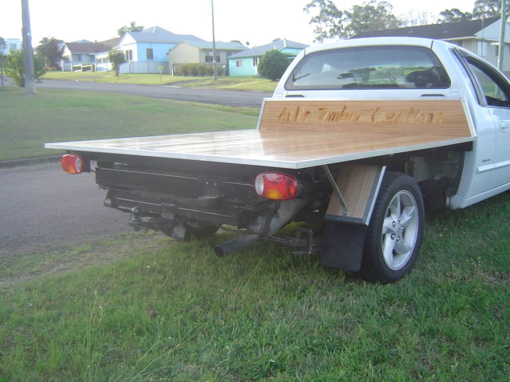
Here's a tray back/bed that I built some time ago. It had my business name in veneer on the head board. It didn't photograph as well as it looked in person, the lettering stood out a lot more. This is the kind of thing I had in mind initially when thinking about a bed for the F1. But older looking and chunkier.
I agree, Corey, it didn't look quite right. I was playing around with what I had but it answered my thoughts by doing so. Originally Posted by JpRngr
Thanks!
12-16-2017 #83
Registered User
- Join Date
- Mar 2012
- Posts
- 288

Subscribing. This is my kind of build.
12-22-2017 #84
Registered User
- Join Date
- Dec 2014
- Posts
- 188
I've done a little bit here and there over the last week but not a lot at a time. The weather finally changed yesterday to being comfortable again. We had a string of days like this, it sucks.
I got those spacers welded to some top plates, followed by completing the drilled holes. The plates will be trimmed down once I work out the sides.
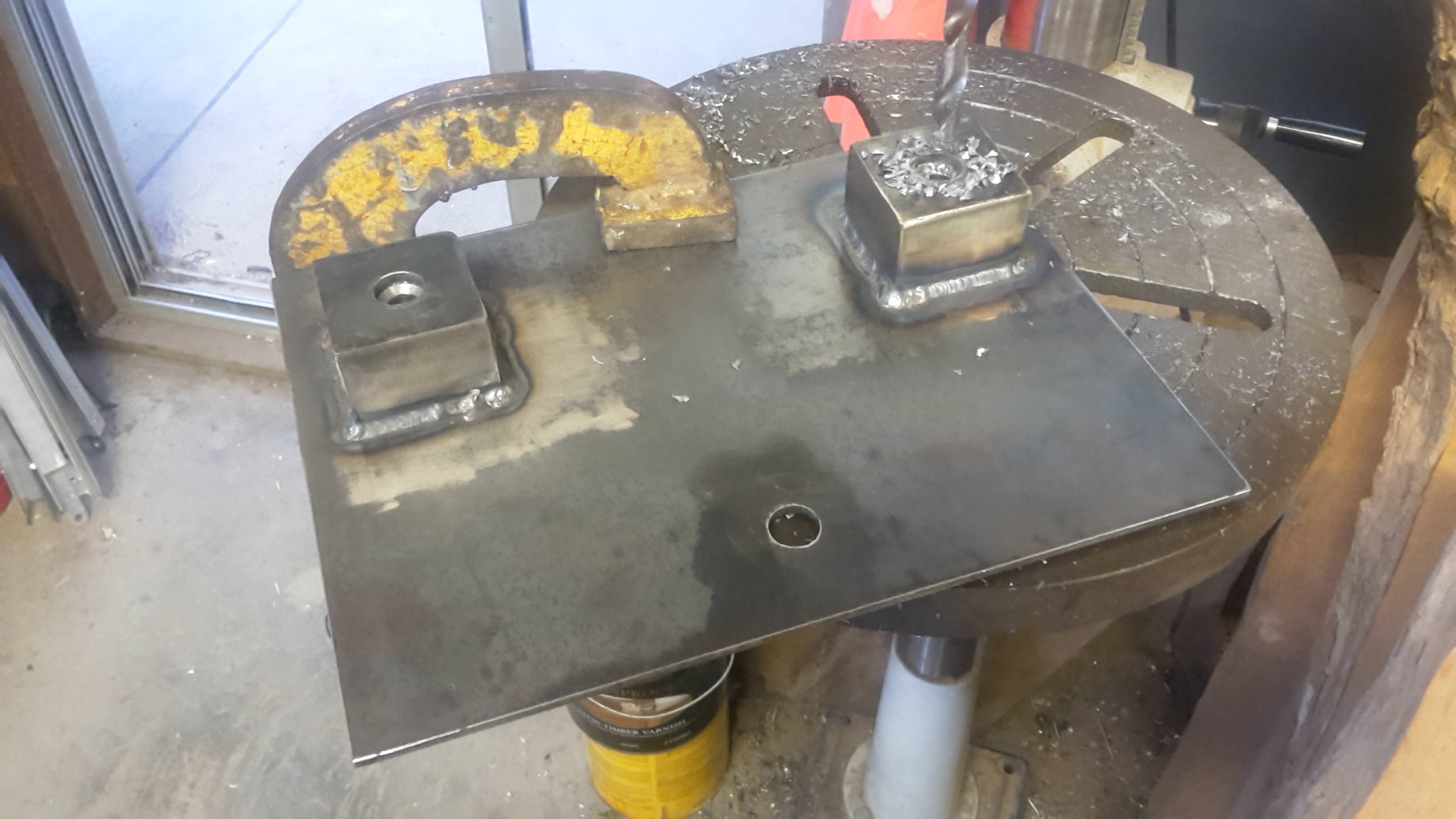
I had to trim down the locating bolts I used on the jig.
and sitting in position
Then it was a matter of repeating to duplicate one for the other side.
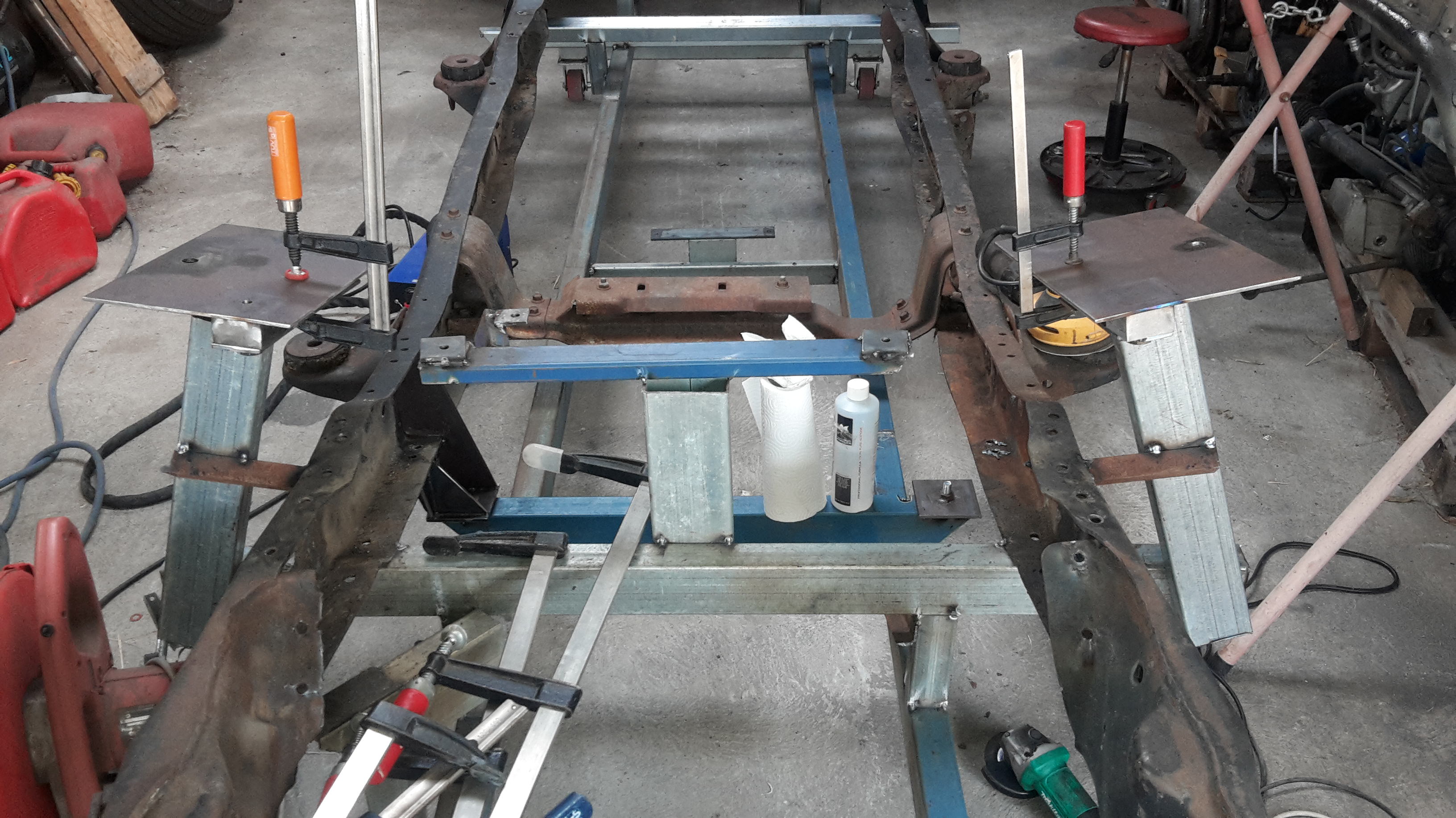
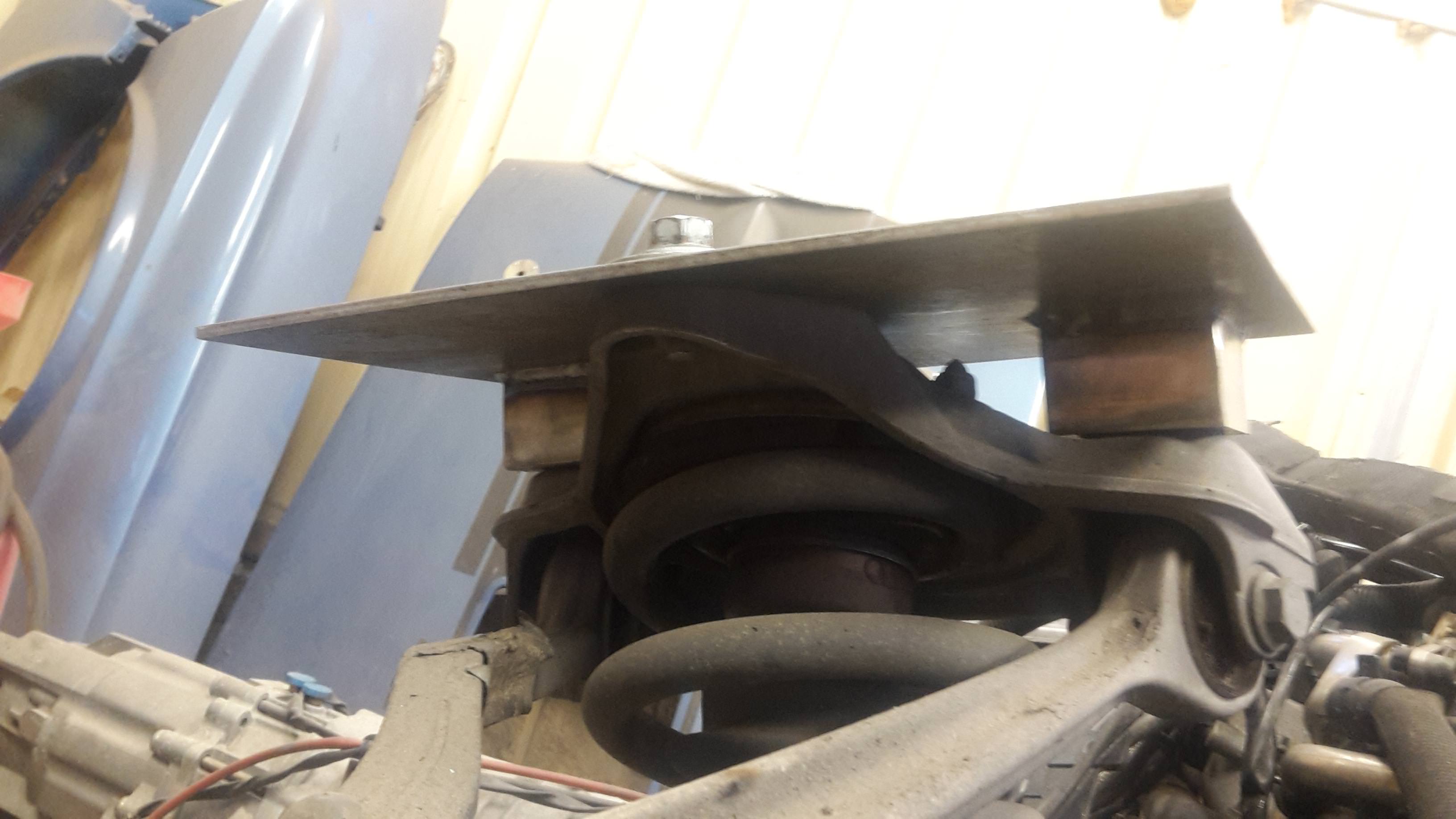
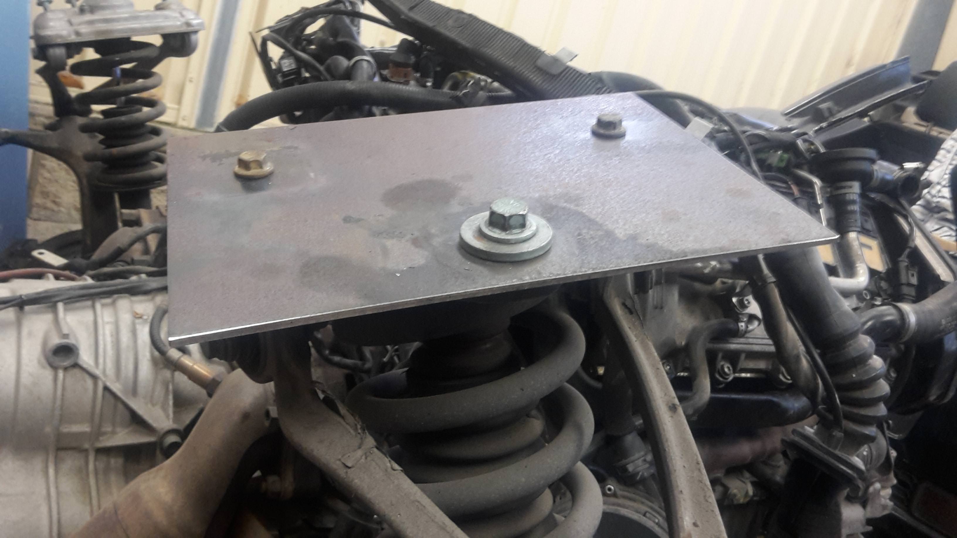
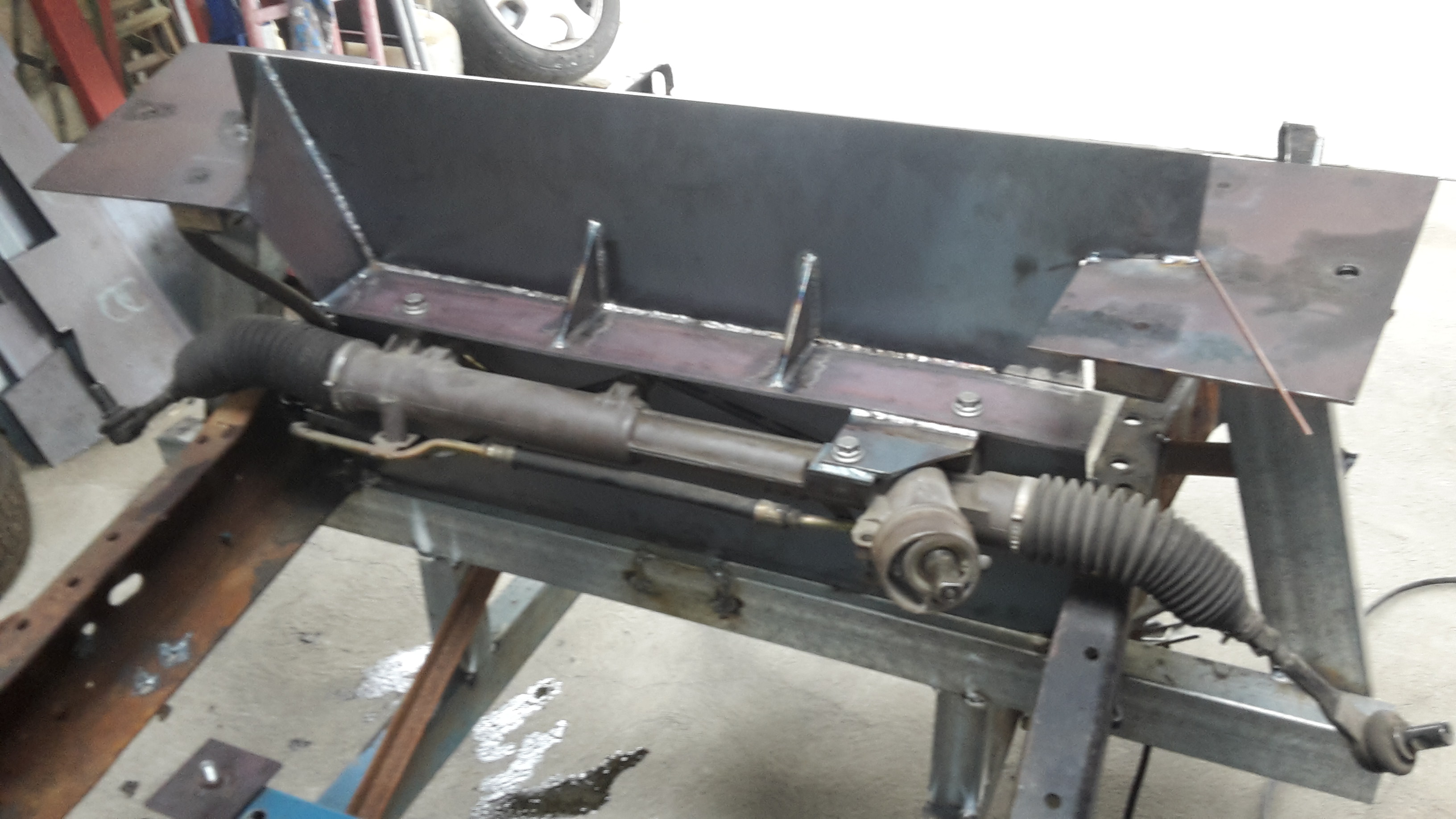
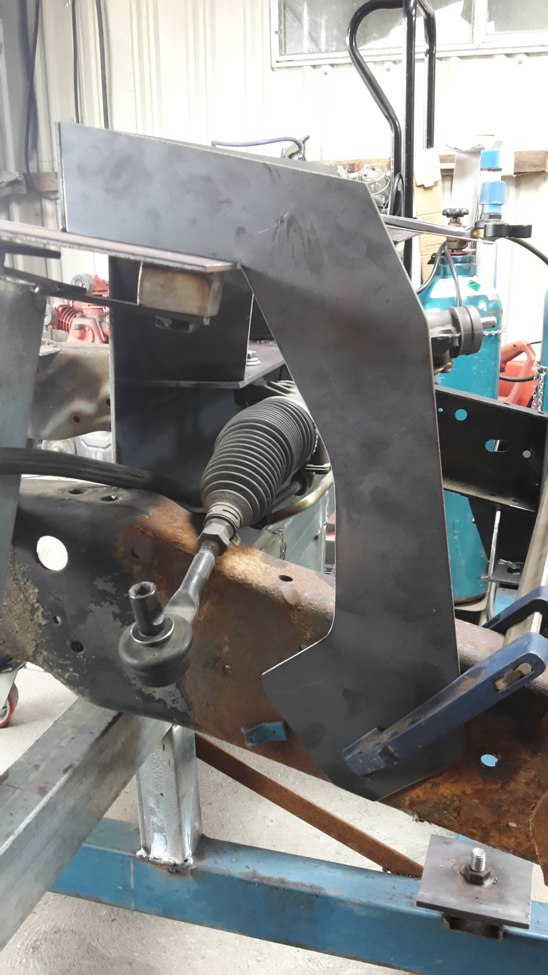
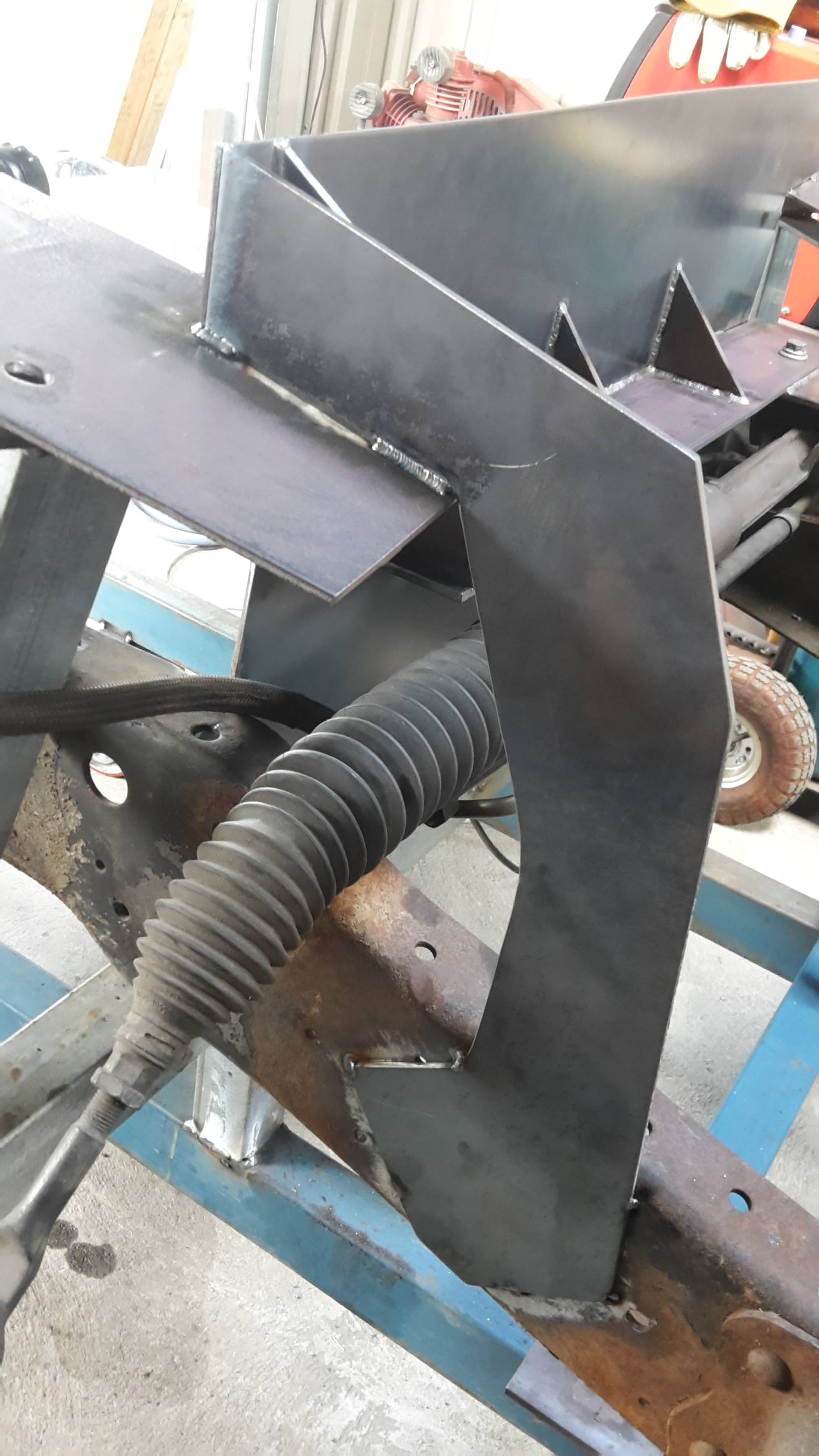
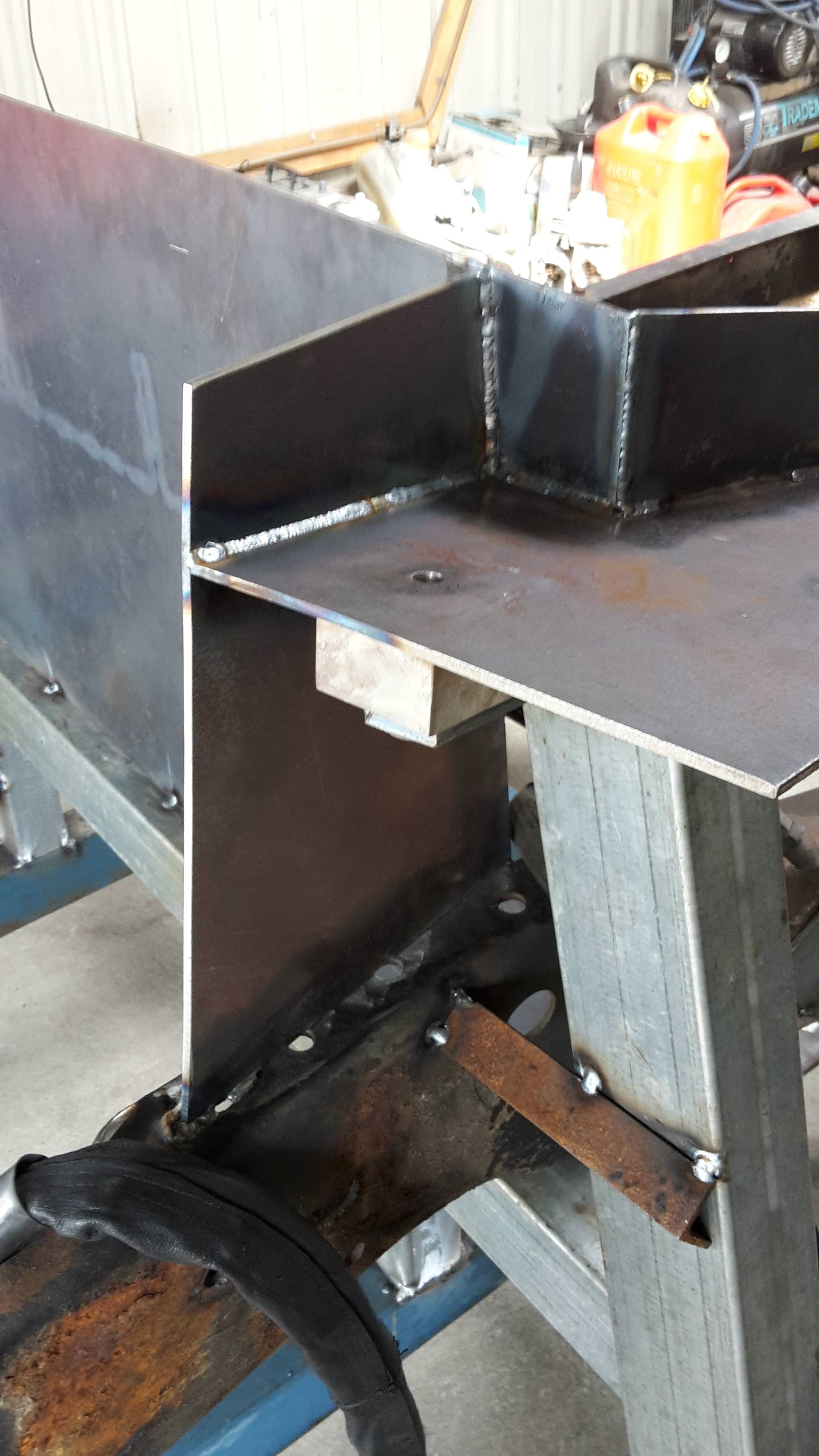
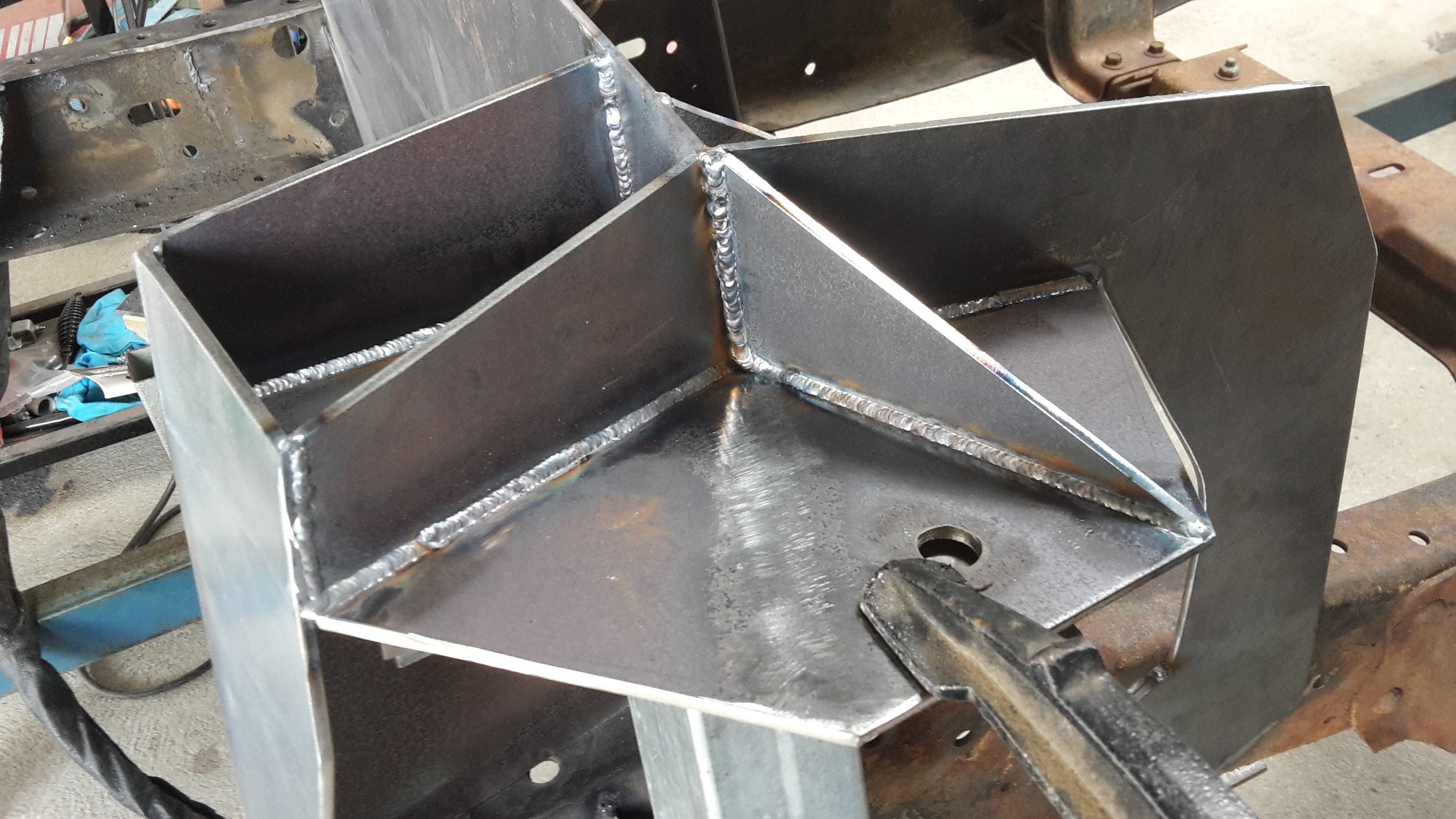
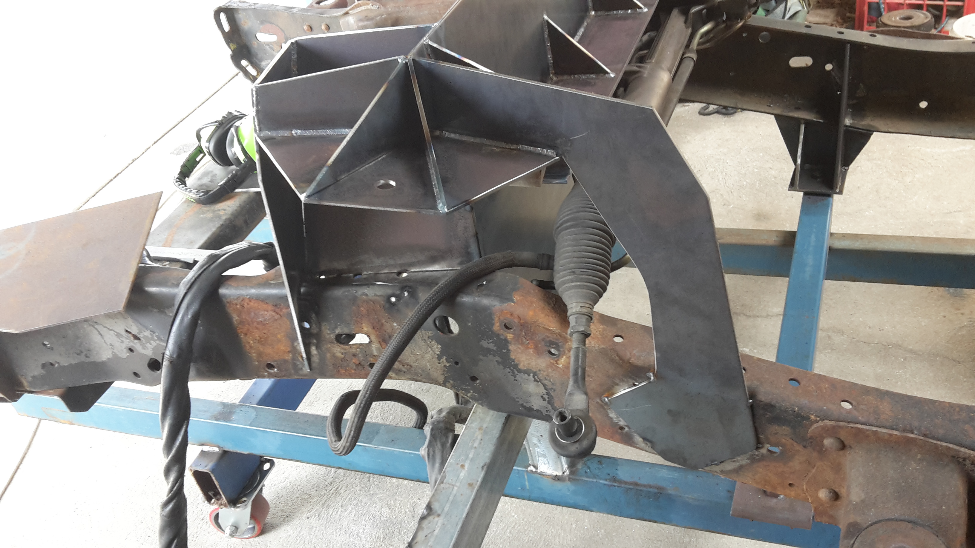
This afternoon I cut some steel to make the power steering rack mount. All three mounting points are on different planes to each other.
and welded it up
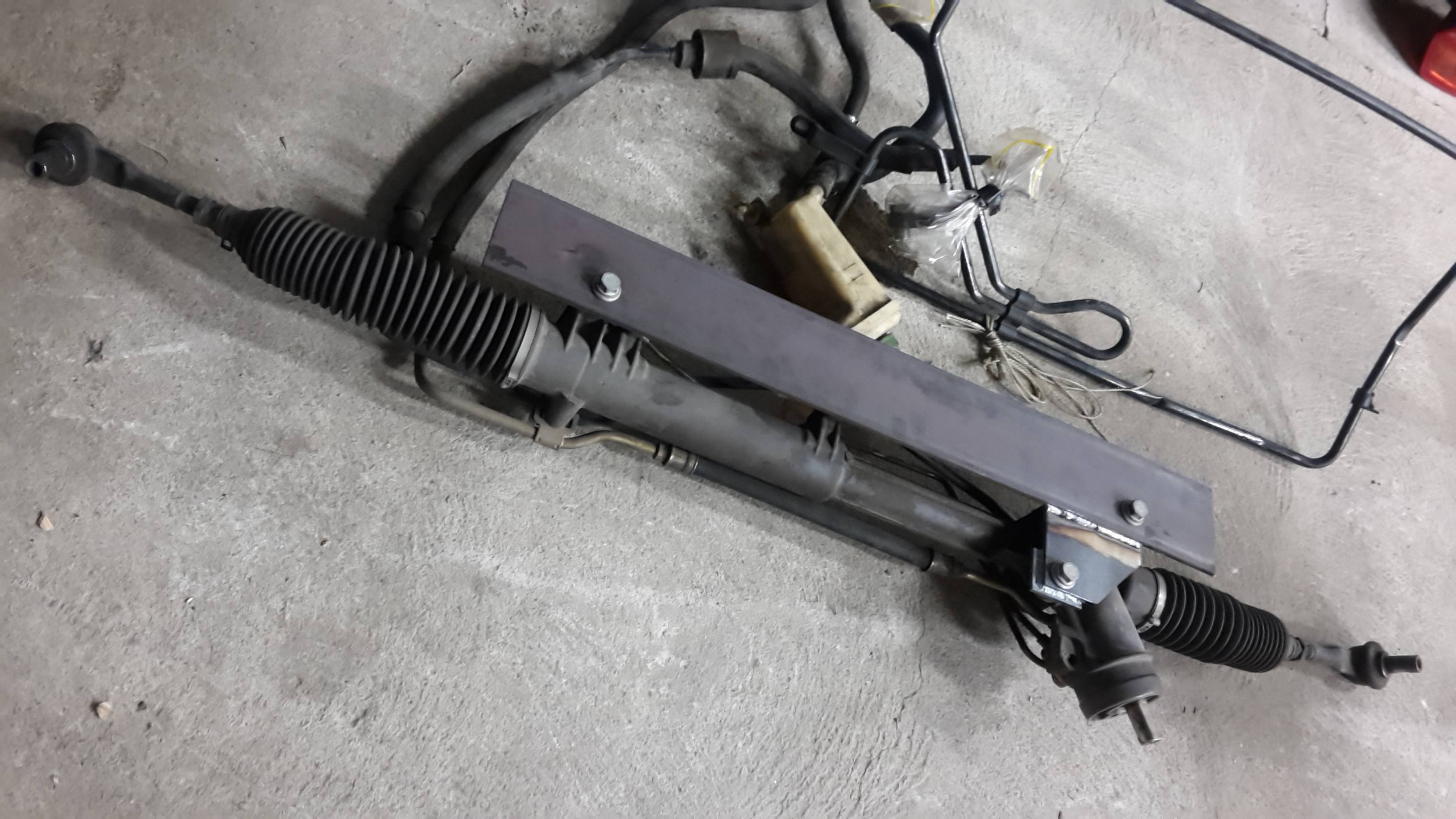
With this made, I can now work on the cross brace that will support he power steering rack, tie into the top of the shock tower mounts and also the insides on the chassis rails.
12-23-2017 #85
Registered User
- Join Date
- Dec 2014
- Posts
- 188
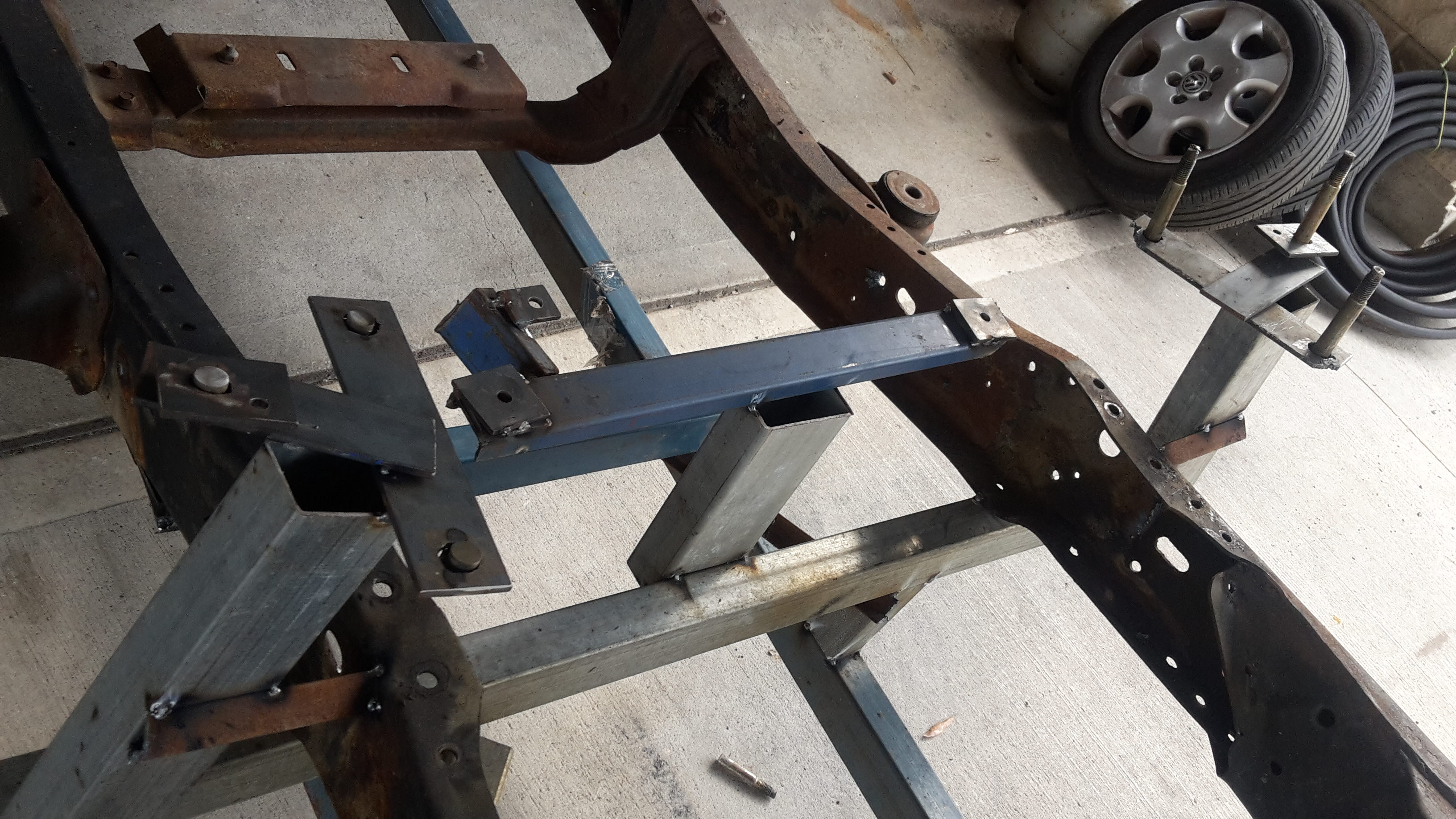
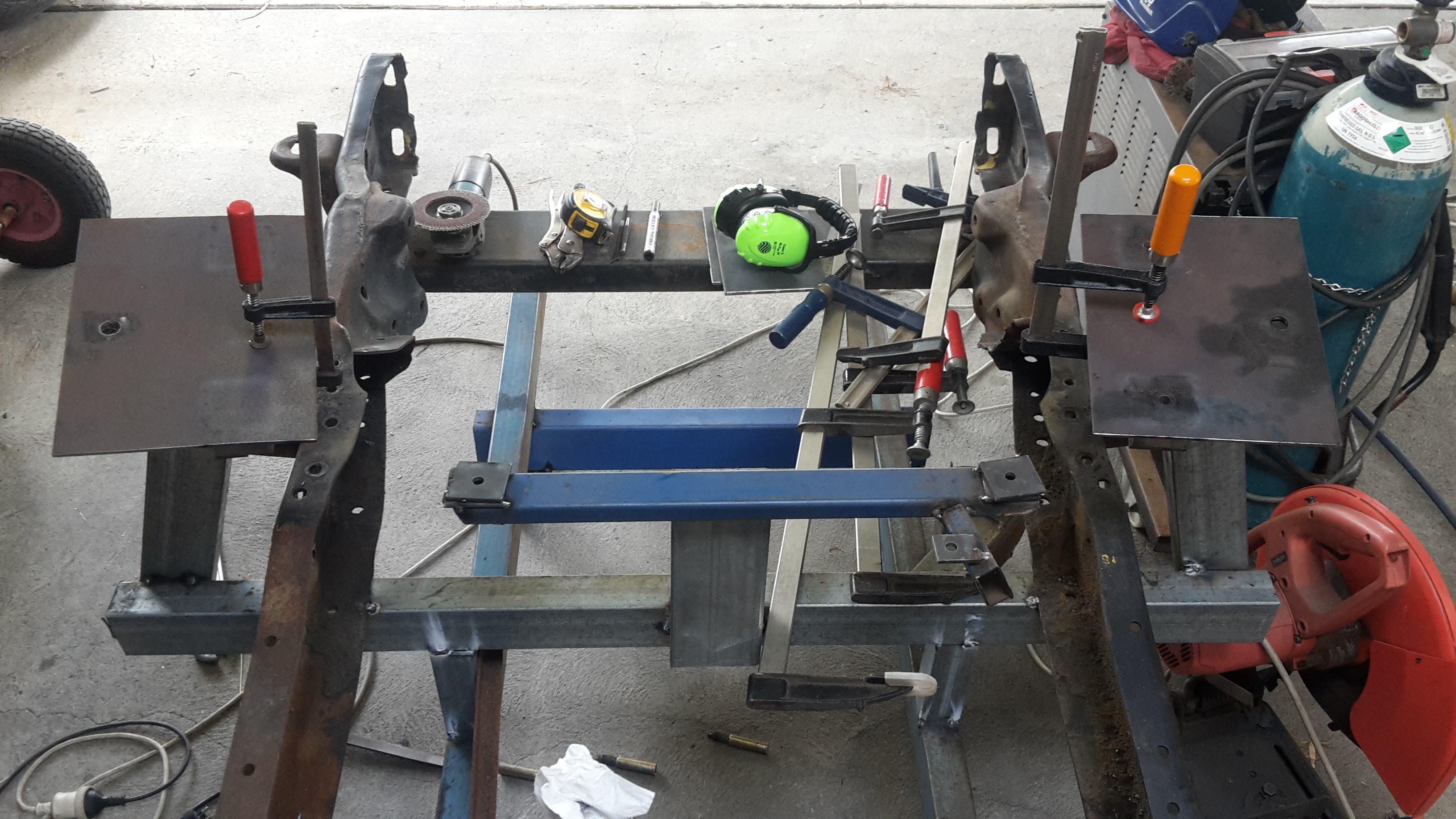
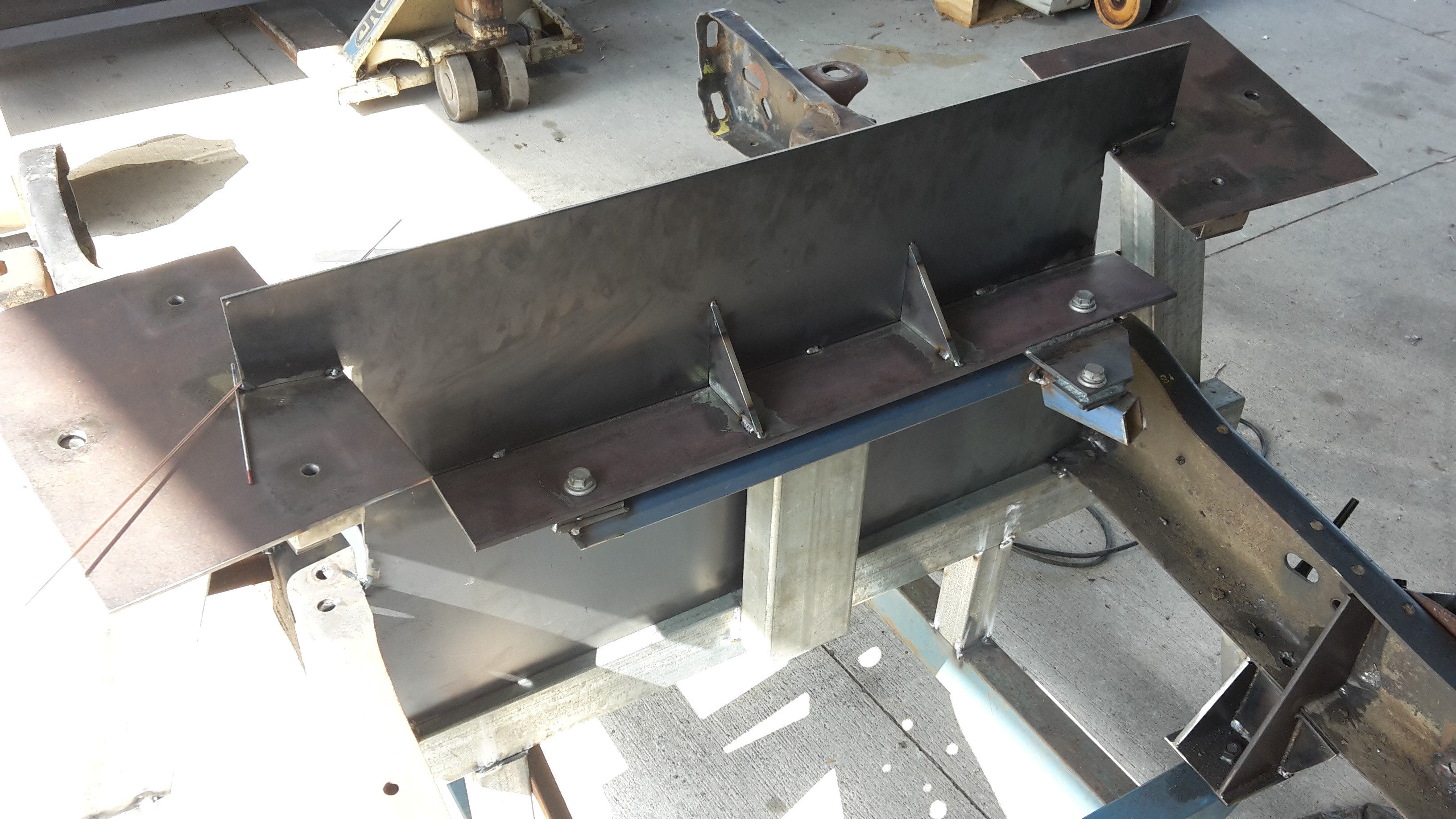
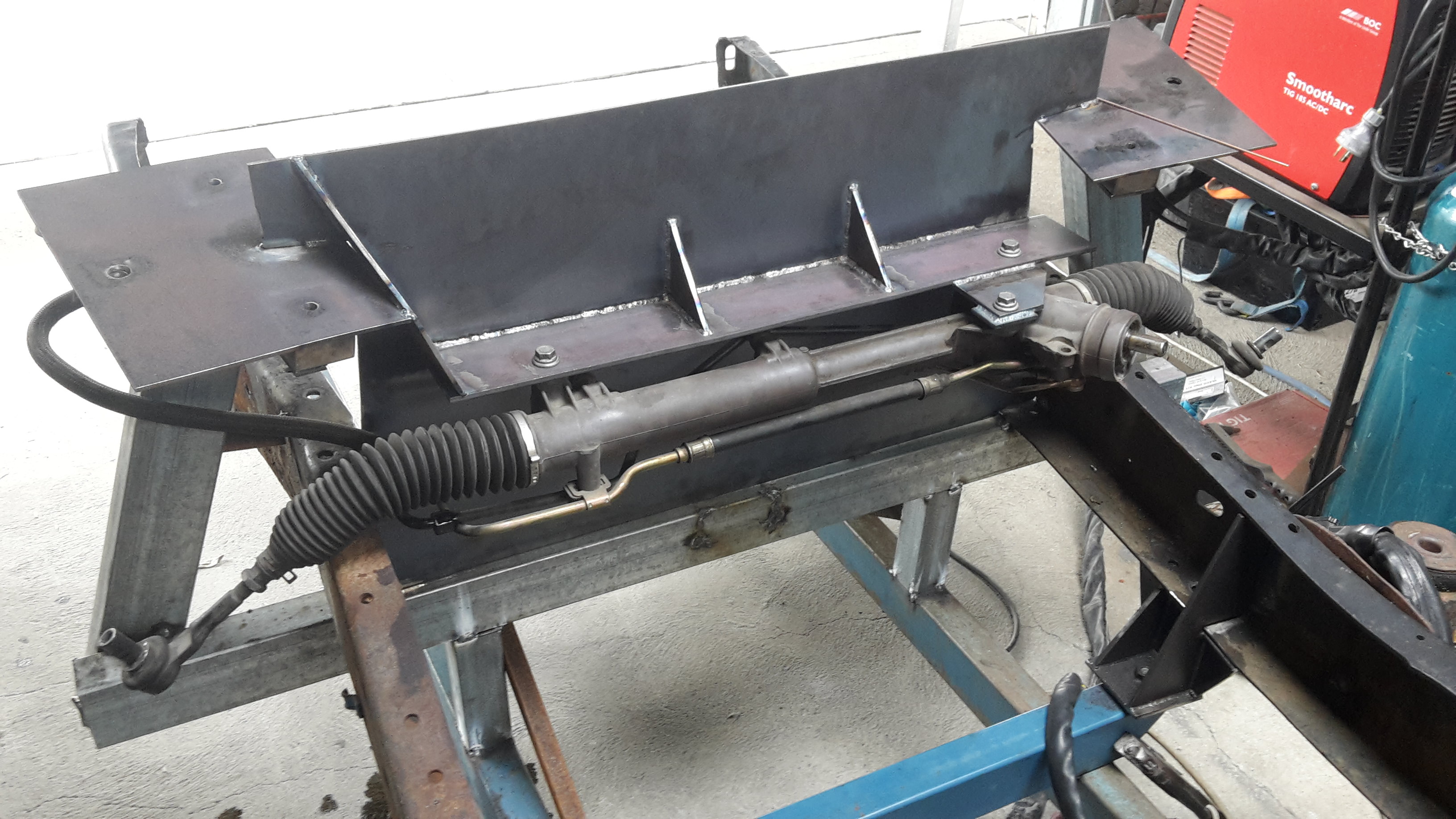
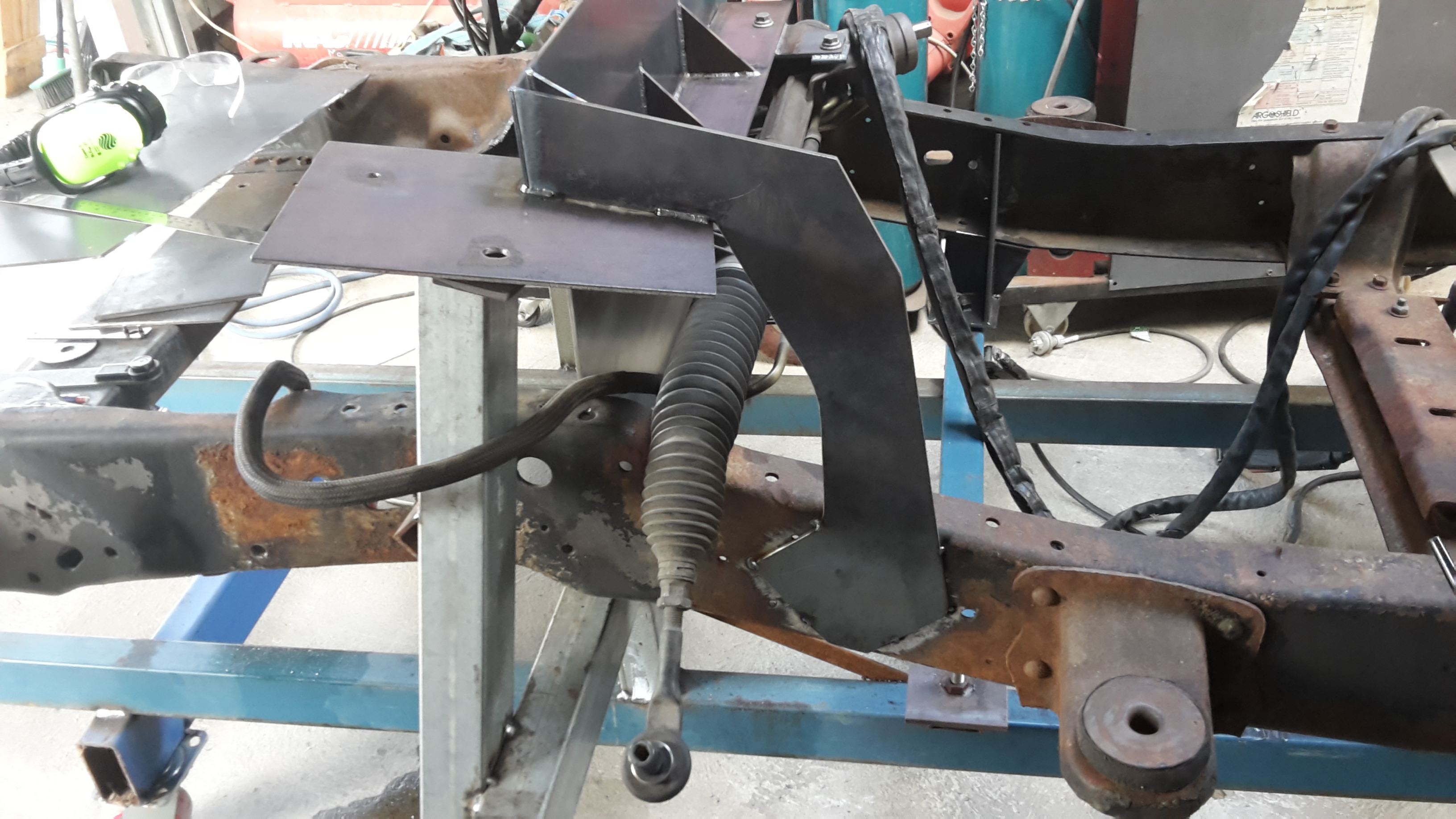
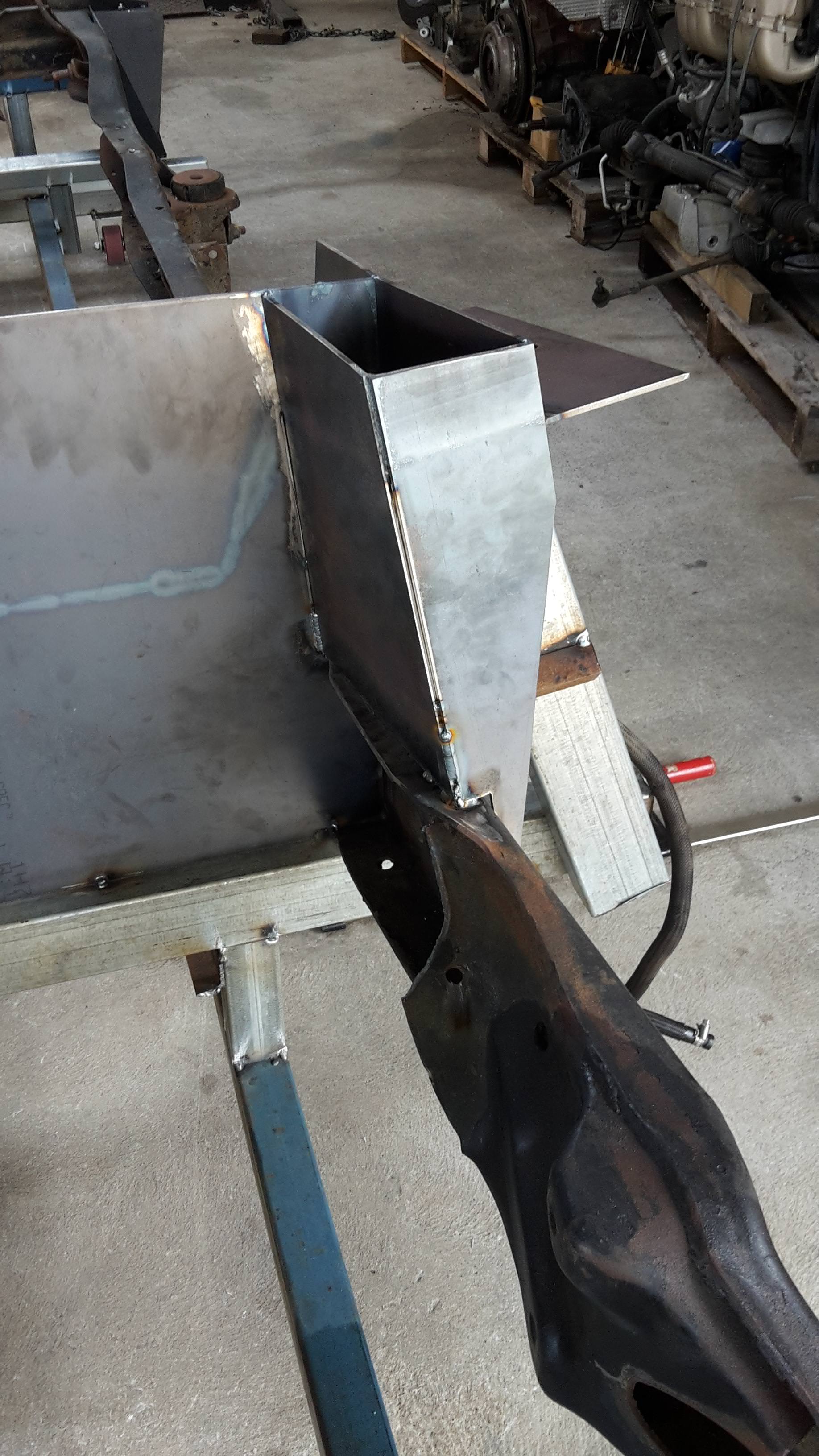
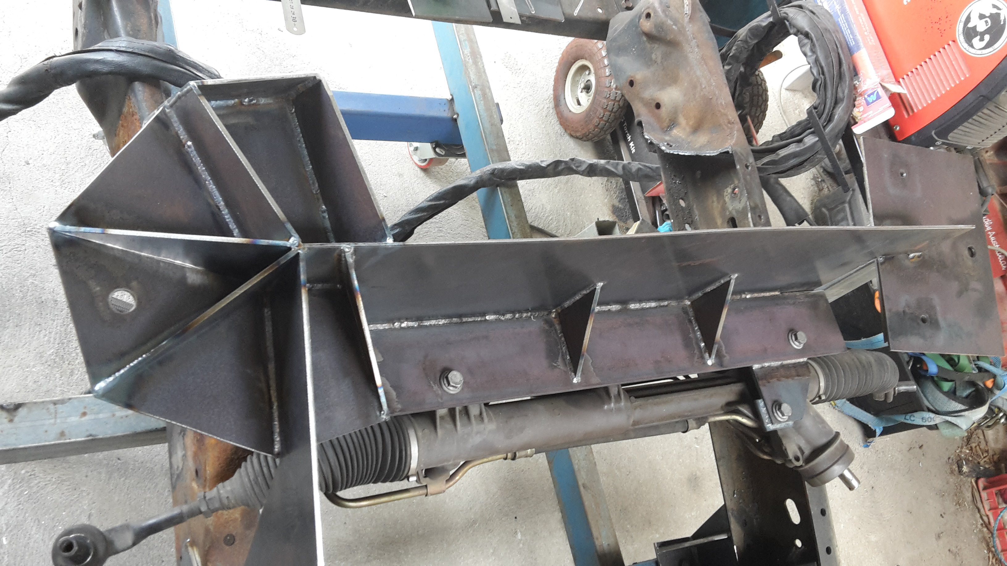
Today I got the plate cut to size and tacked into position, it ties the shock tower tops to the chassis rails as well as supports the power steering rack.
The bottom side of it will get cut out for transmission clearance once everything is welded up.
12-25-2017 #86
Registered User
- Join Date
- Dec 2014
- Posts
- 188
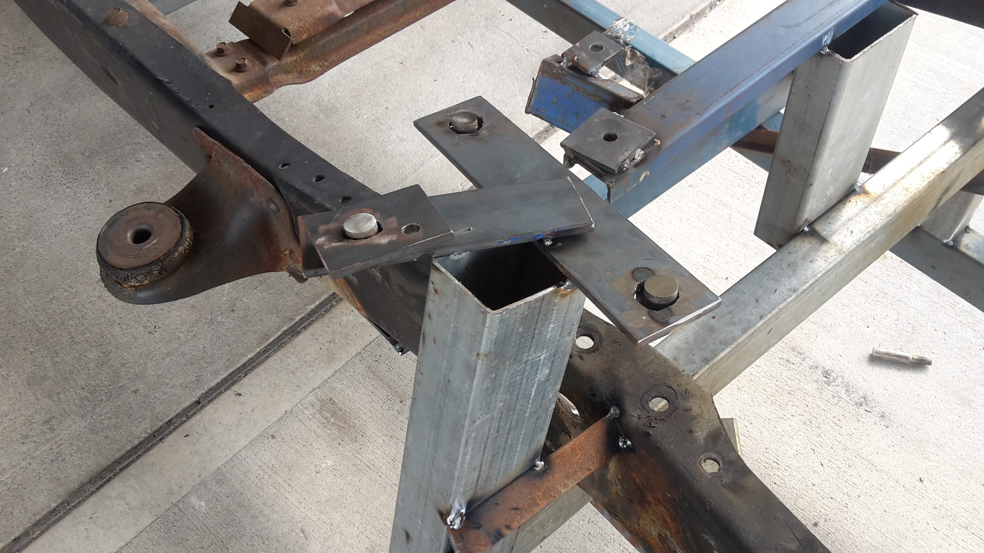
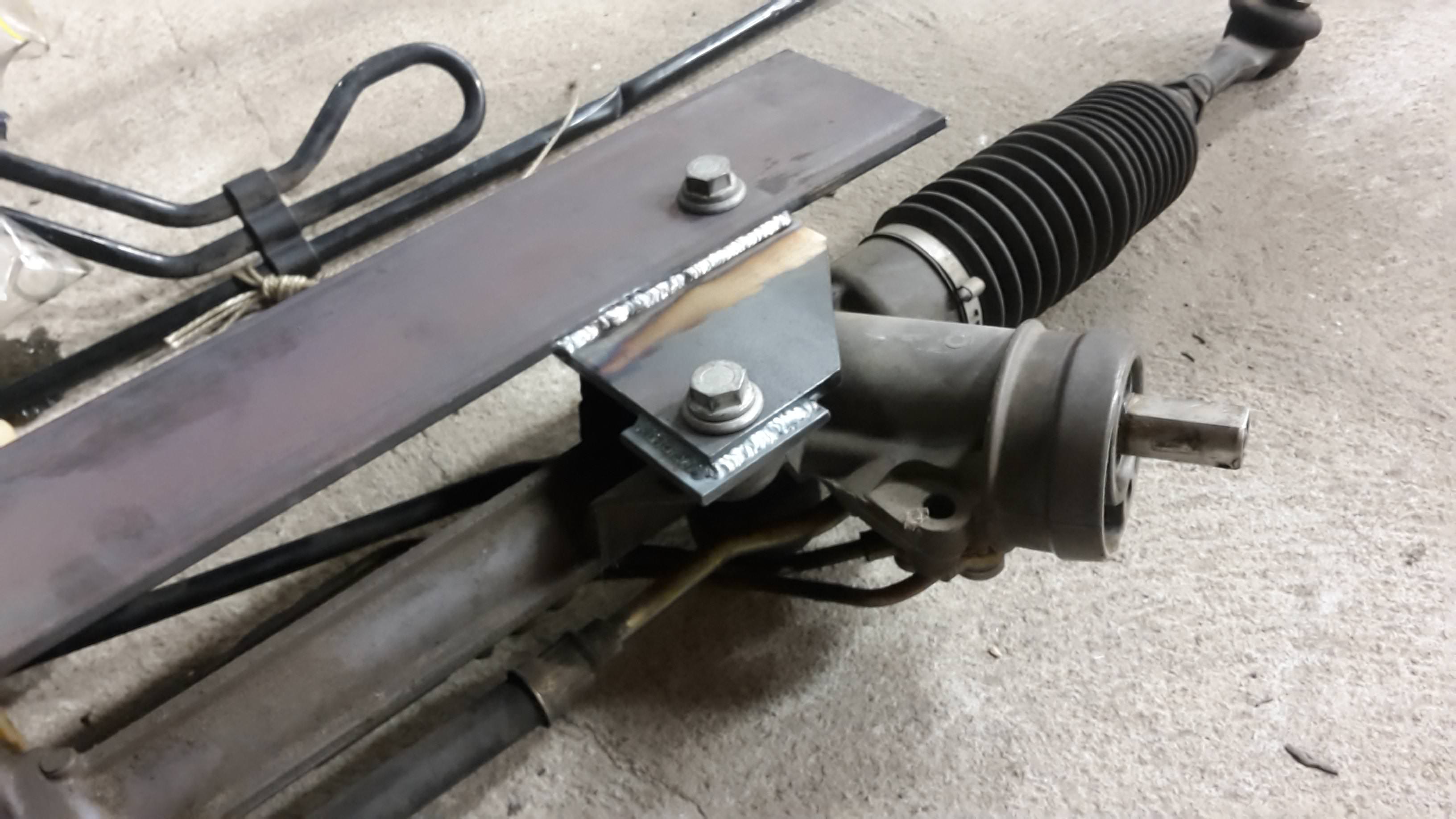
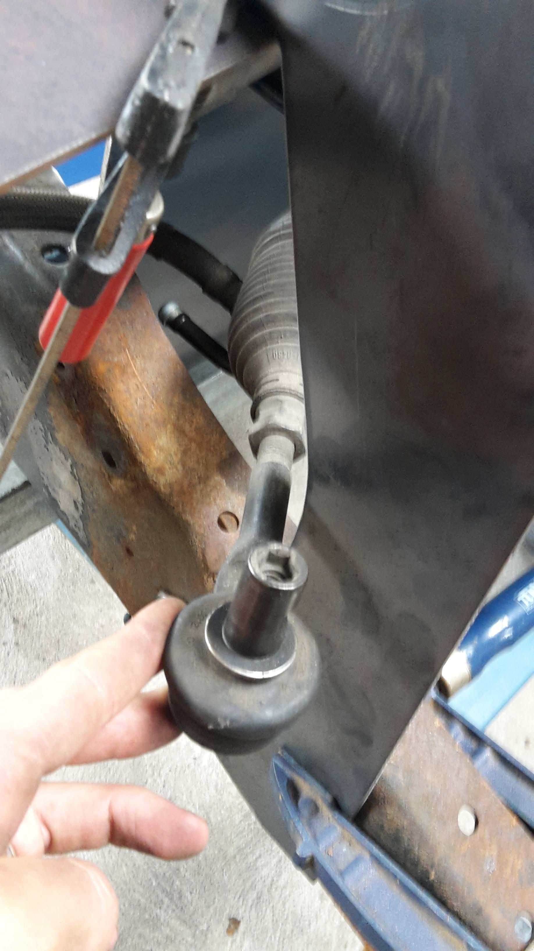
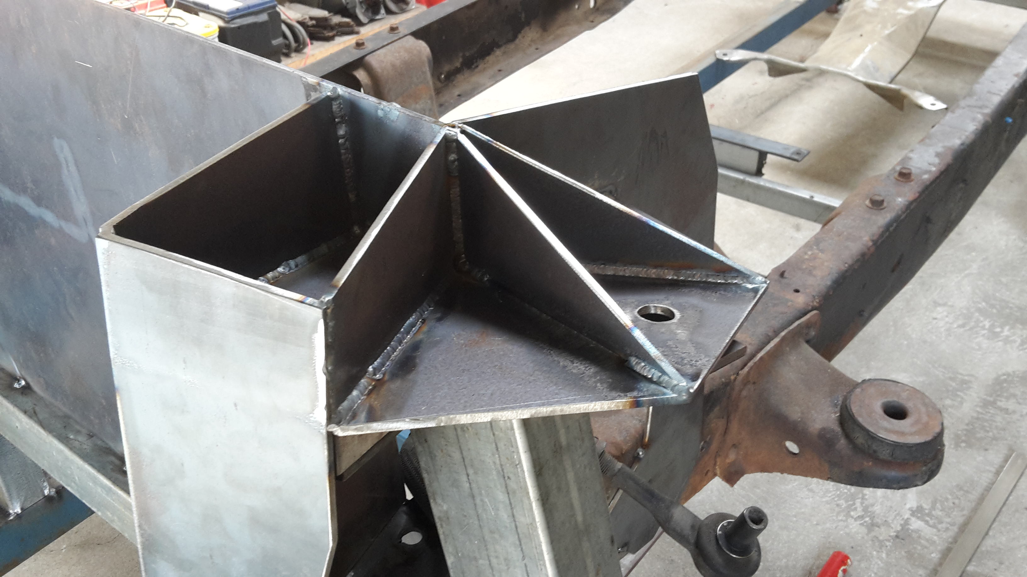
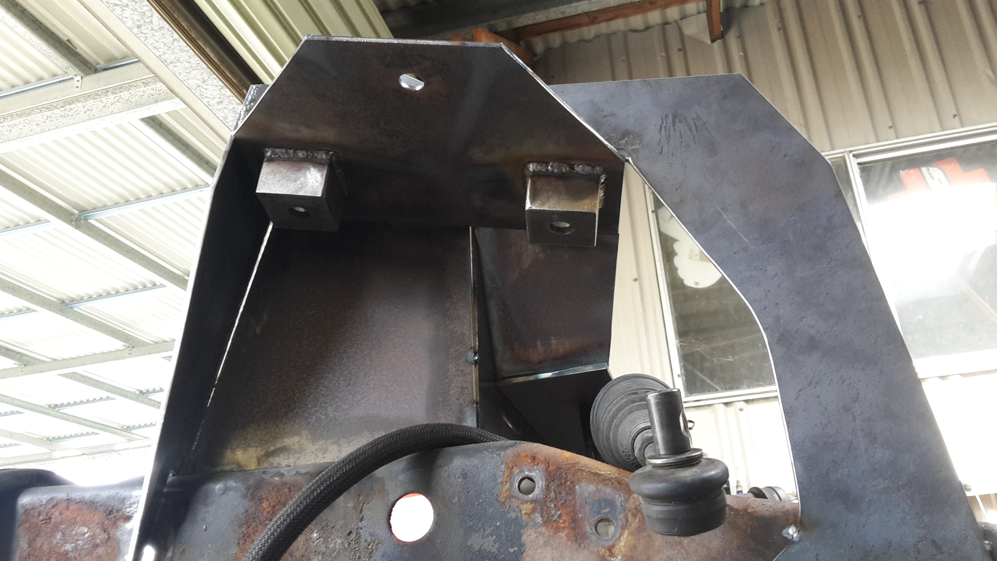
Welded a plate to tie the shock tower to the rack mount on the left side. And finished welding up the rest. I fitted the rack so that I can now fab the rest of the shock tower to clear the rack.
Oh, and Merry Christmas everyone.
12-26-2017 #87 Registered User
- Join Date
- Aug 2008
- Location
- jacksonville,fl
- Posts
- 970
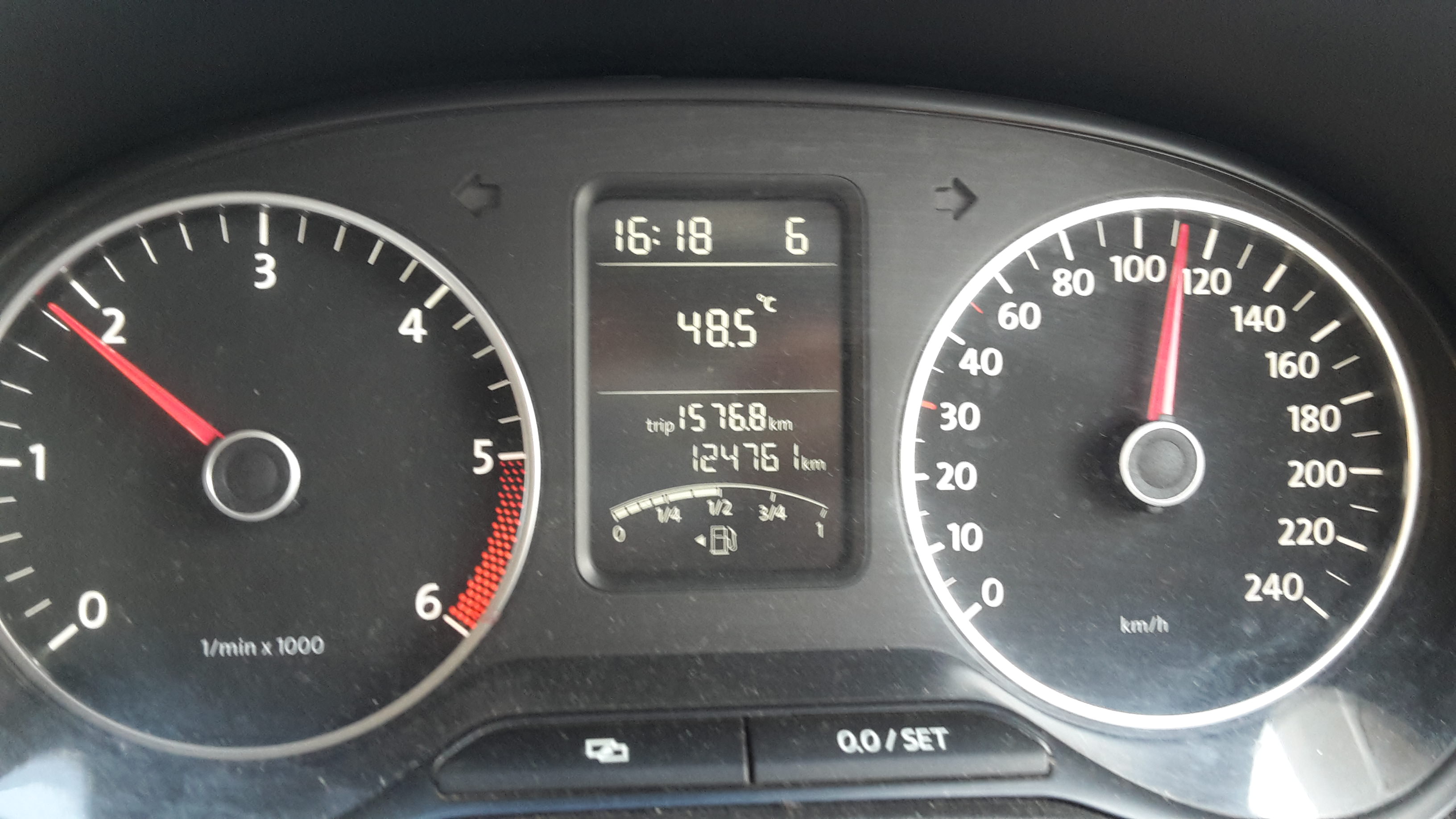
Had to google what 48.5degrees celcius converted to here, 119.3 degrees faienheit. DAMN, hope that reading was off the pavement or vehicle metal & not the air.I should hope at least it's not damp heat like we have in florida here.
Any progress after that is good progress, cheers.
I'll be home almost another 2 weeks from my little surgery. If I get bored enough, I may draw a front/ side angle picture of a 50.
12-26-2017 #88
Registered User
- Join Date
- Dec 2014
- Posts
- 188
That's air temp and yep, humid too. Last year we had week on week of low and mid 50°C. It hasn't been that bad this year, thankfully.
Hope the recovery is going well for you.
12-27-2017 #89
Registered User
- Join Date
- Jan 2015
- Location
- Australia
- Posts
- 284
Great build. Will be following this.
Love the ideas from everyone on the forum.
Keep going its inspiring.
12-27-2017 #90
Registered User
- Join Date
- Dec 2014
- Posts
- 188
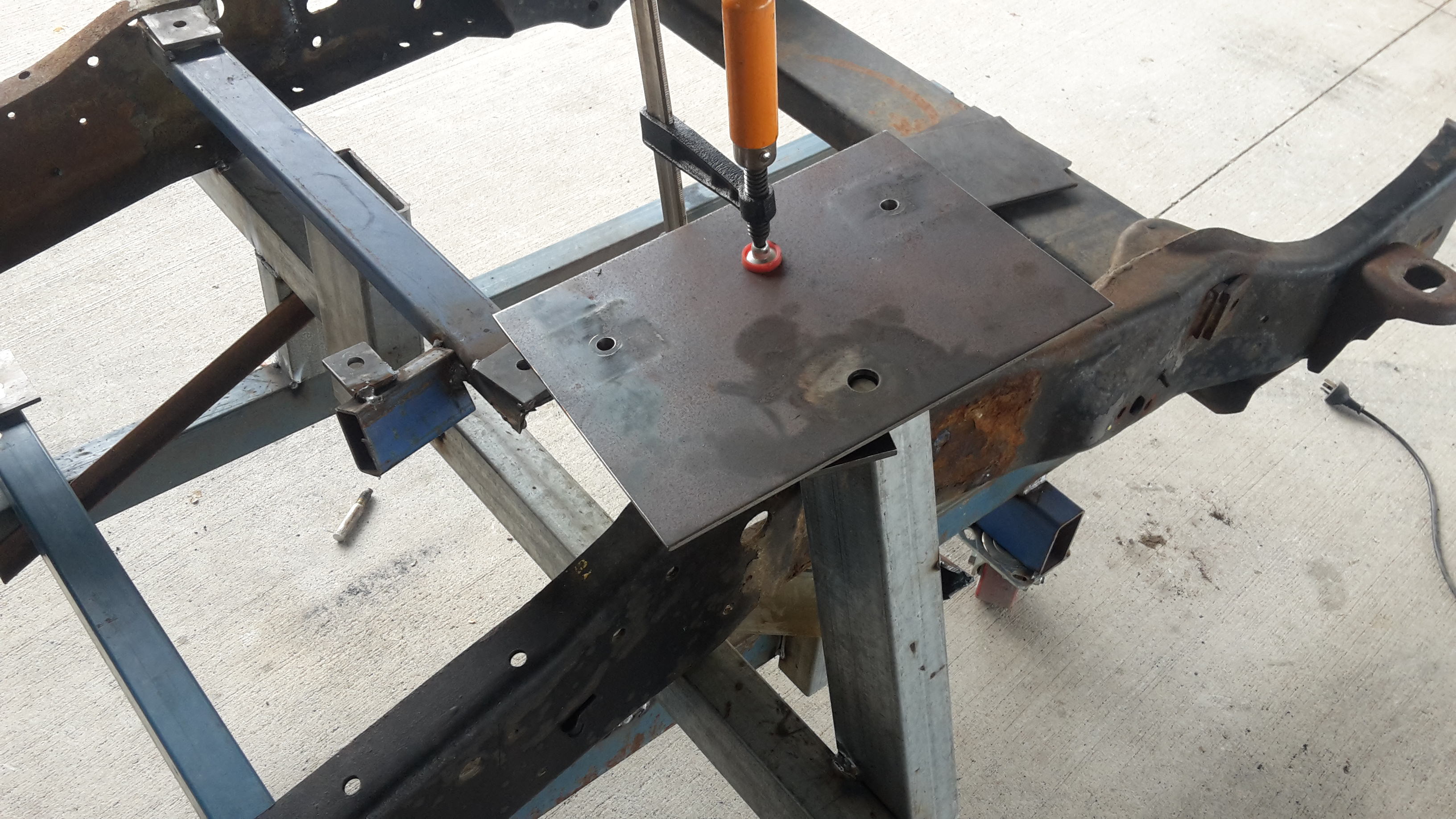
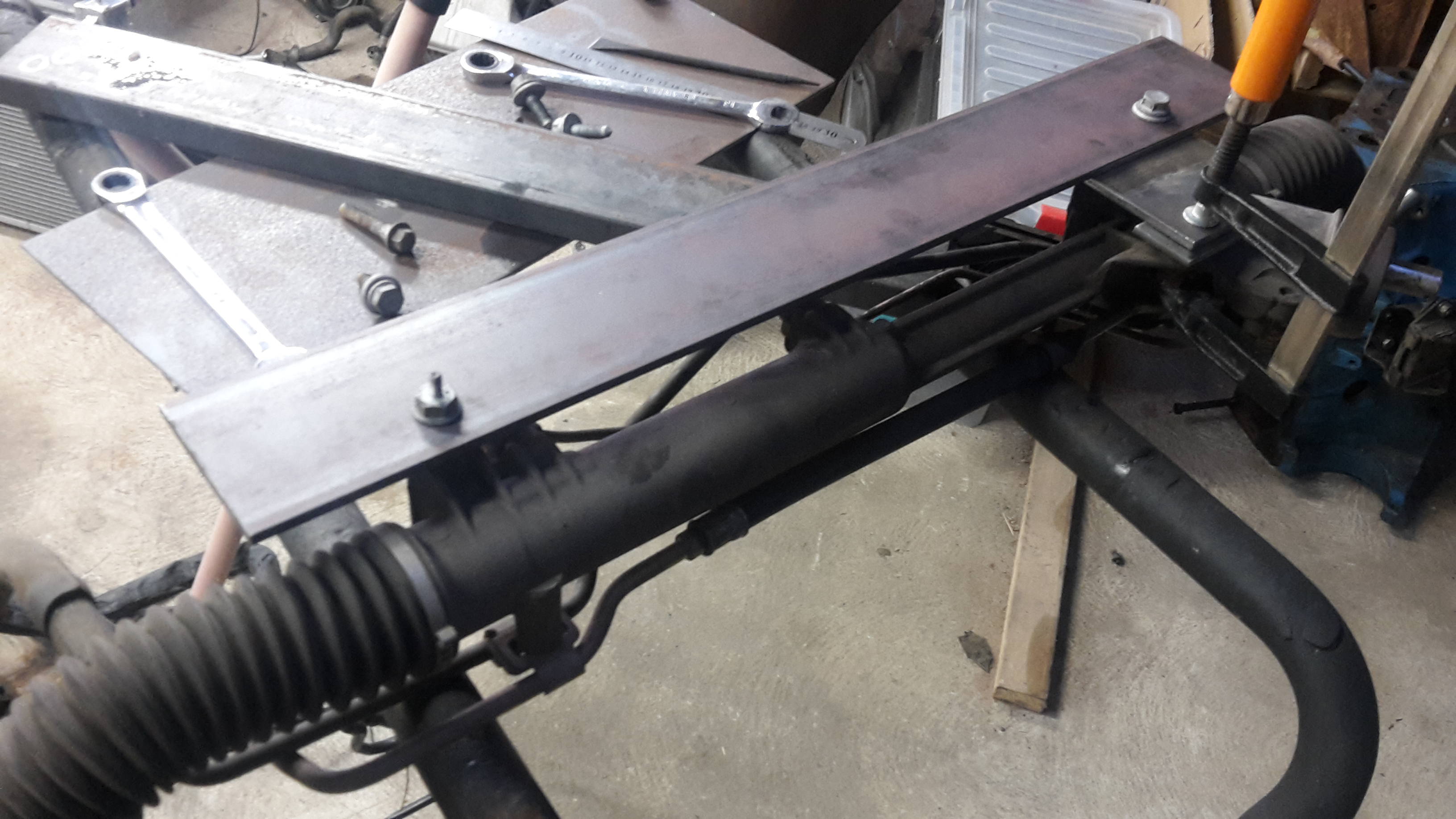
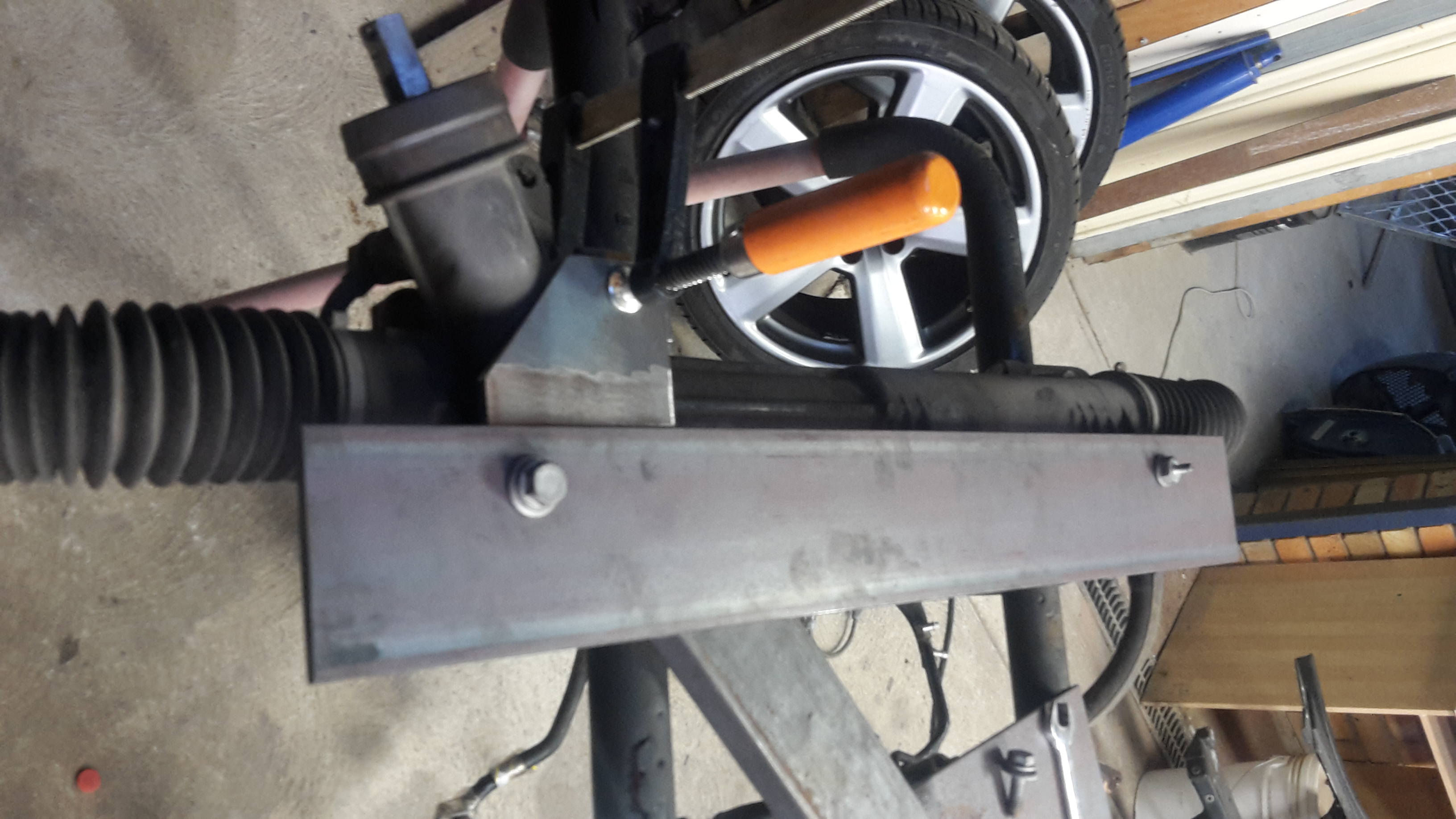
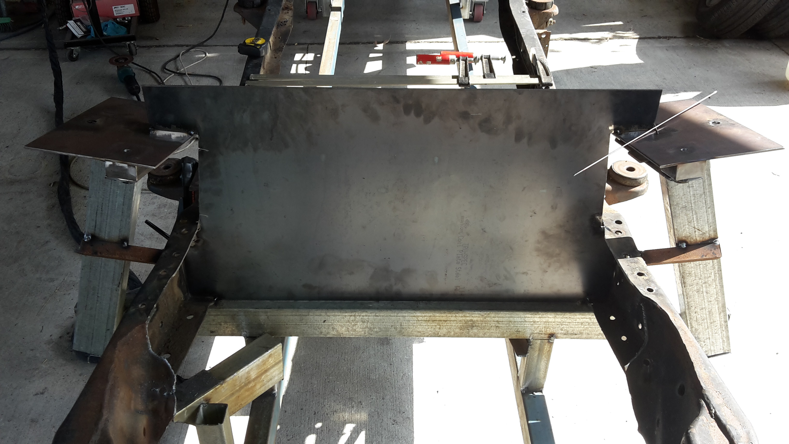
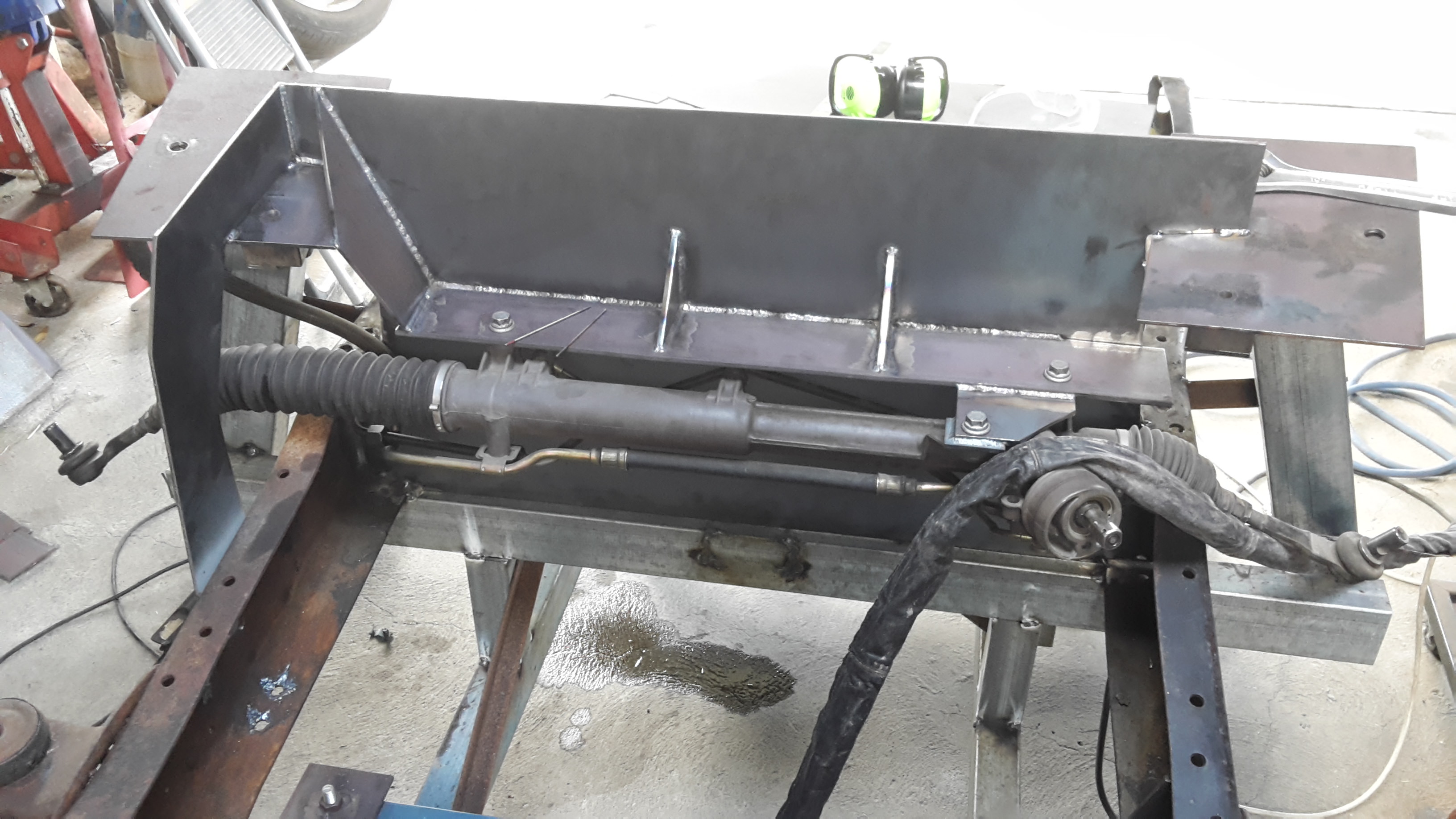
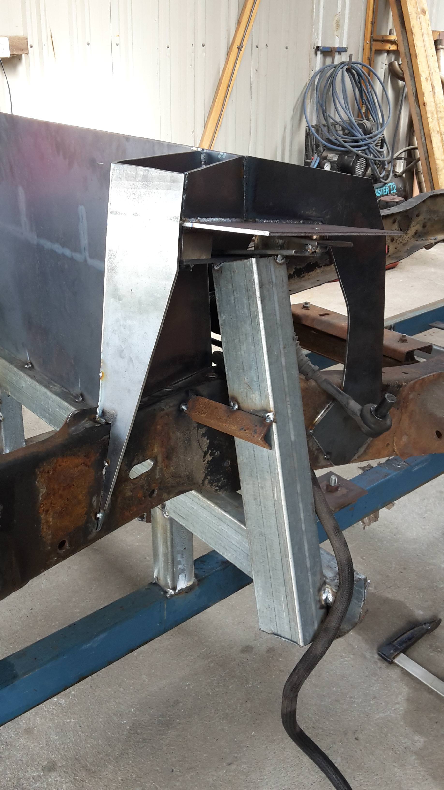
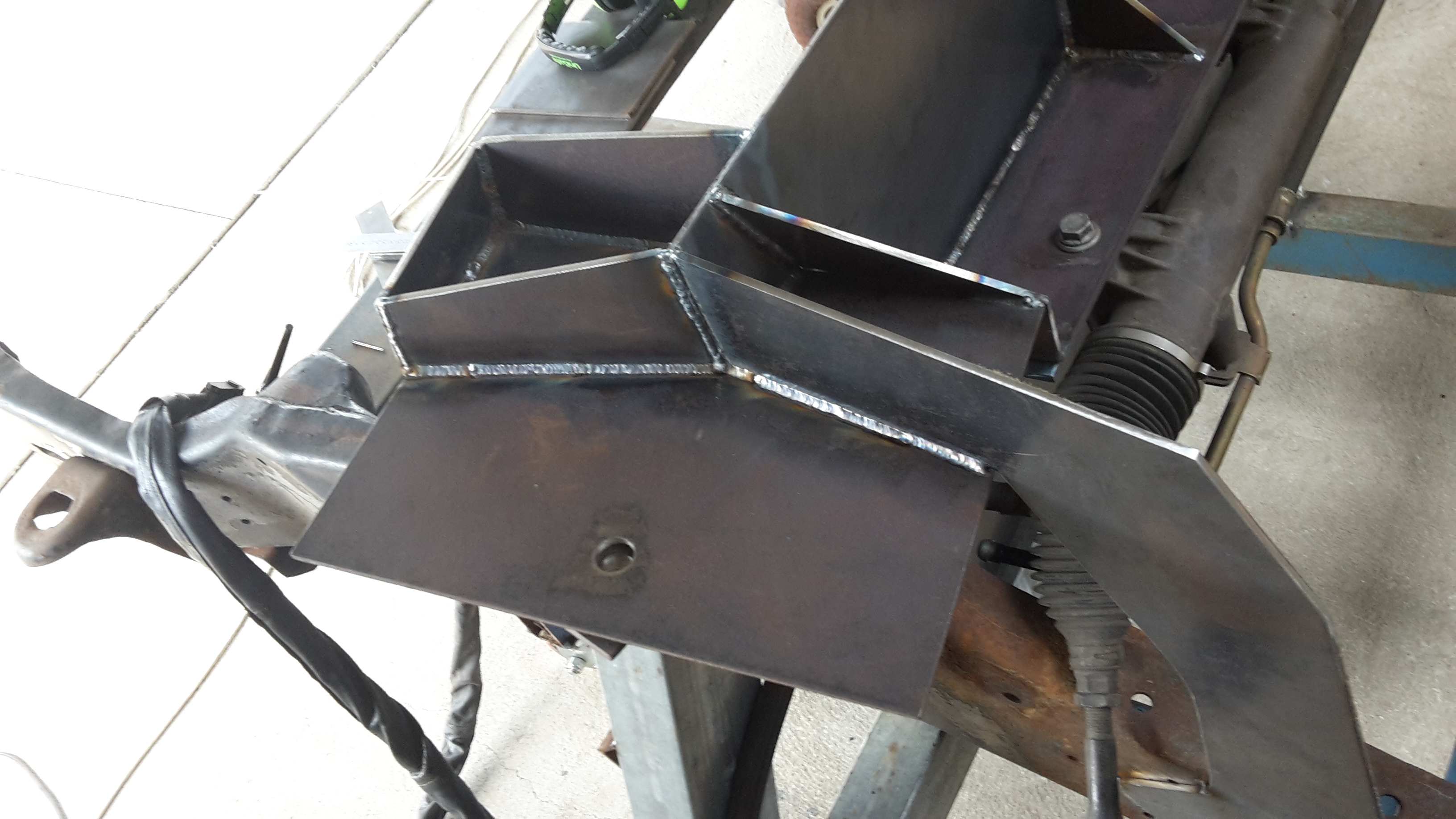
I did some CAD (cardboard aided design) work this arvo.
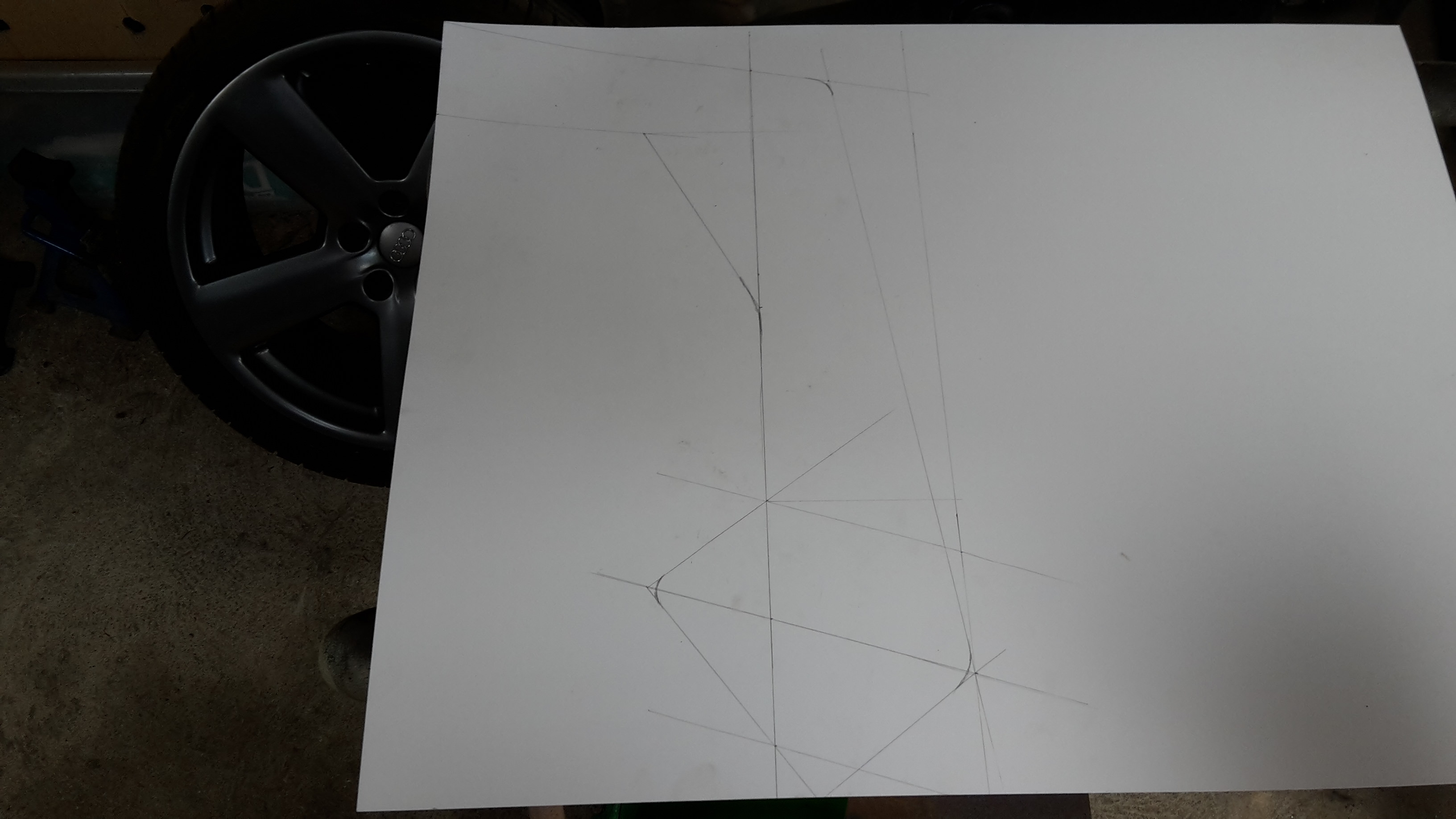
It needed to clear the steering rack at all angles
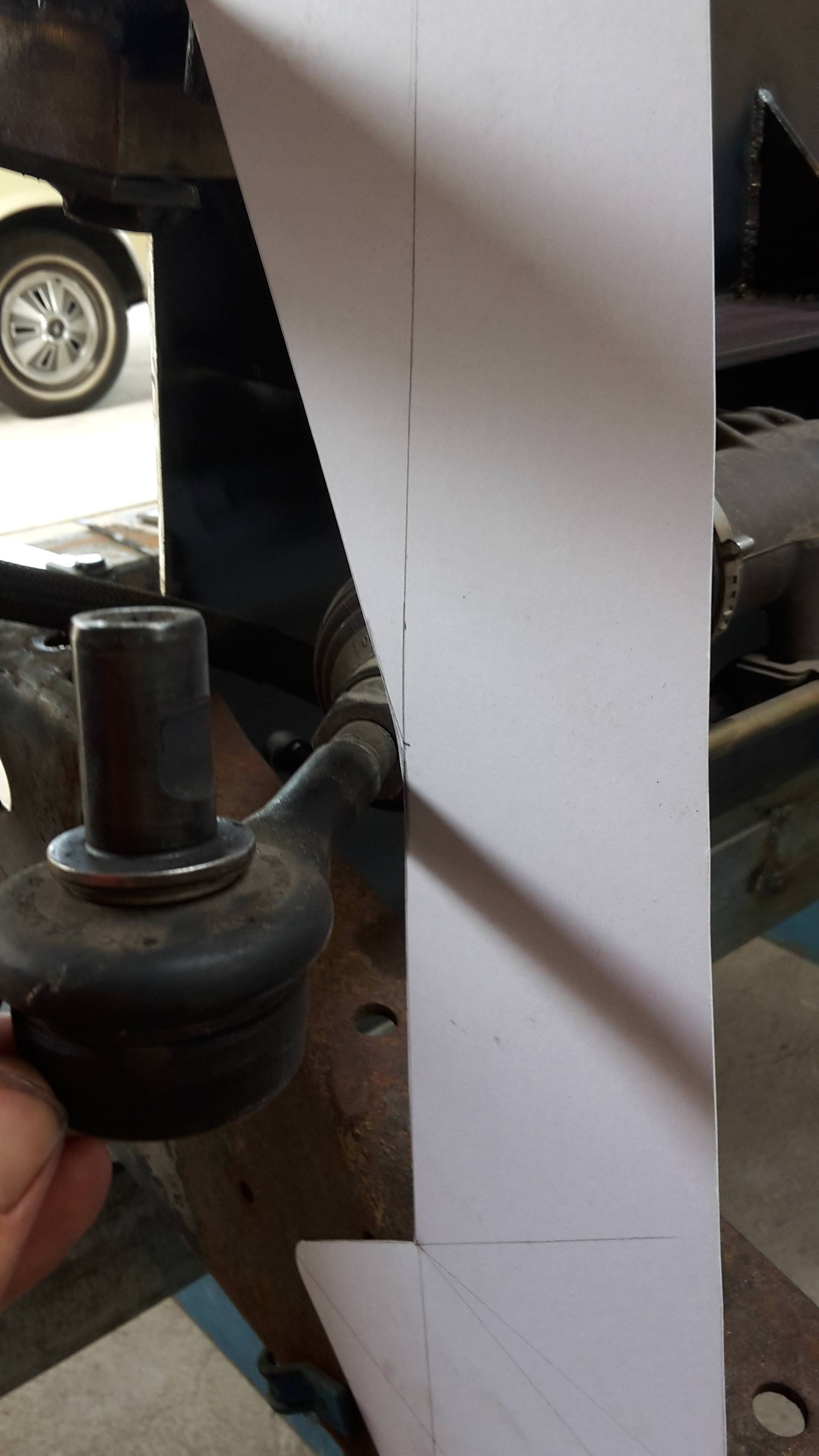
and best of all, the angle was by chance a perfect match to a previous cut. Woo hoo, winning! ha
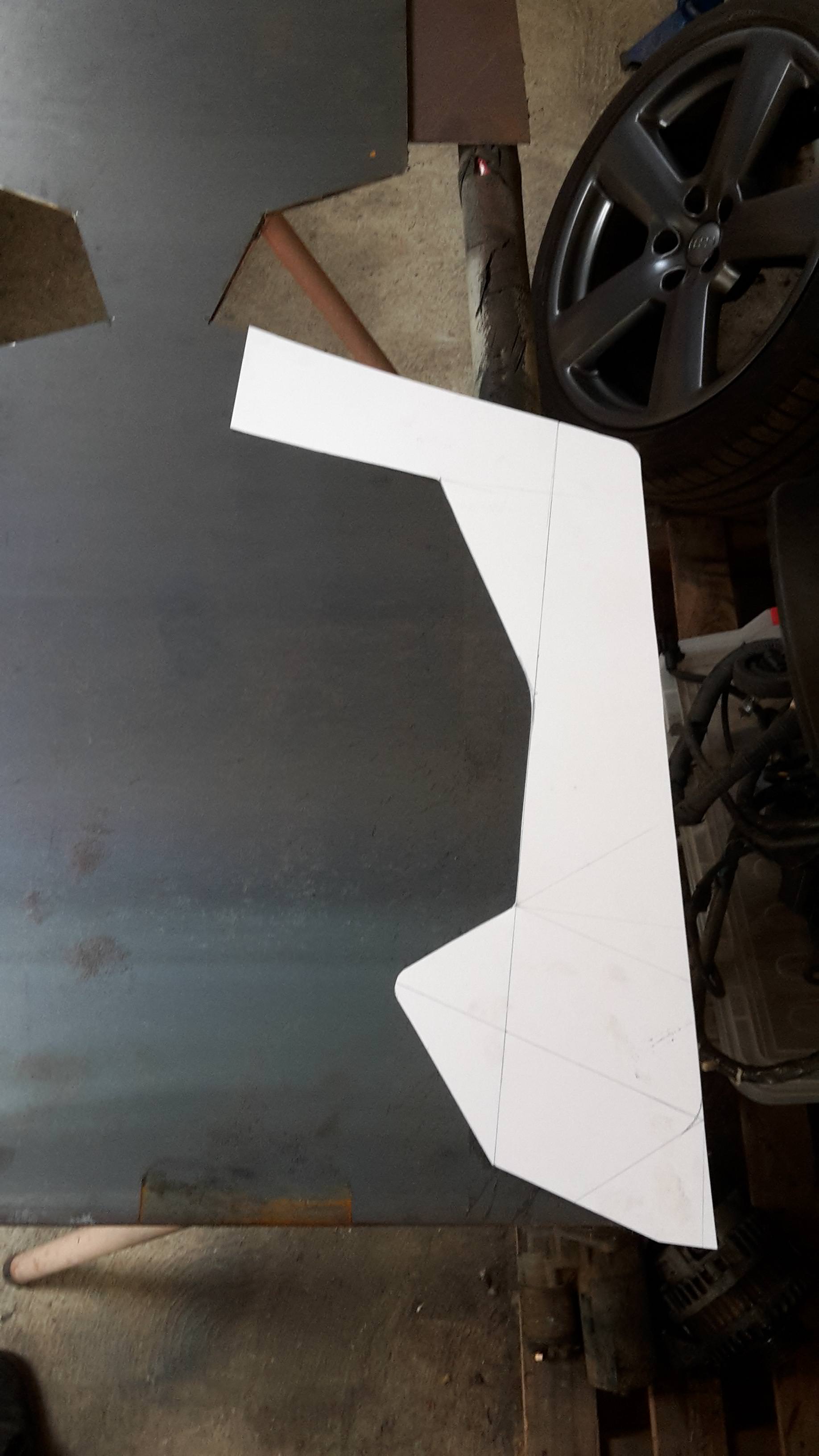
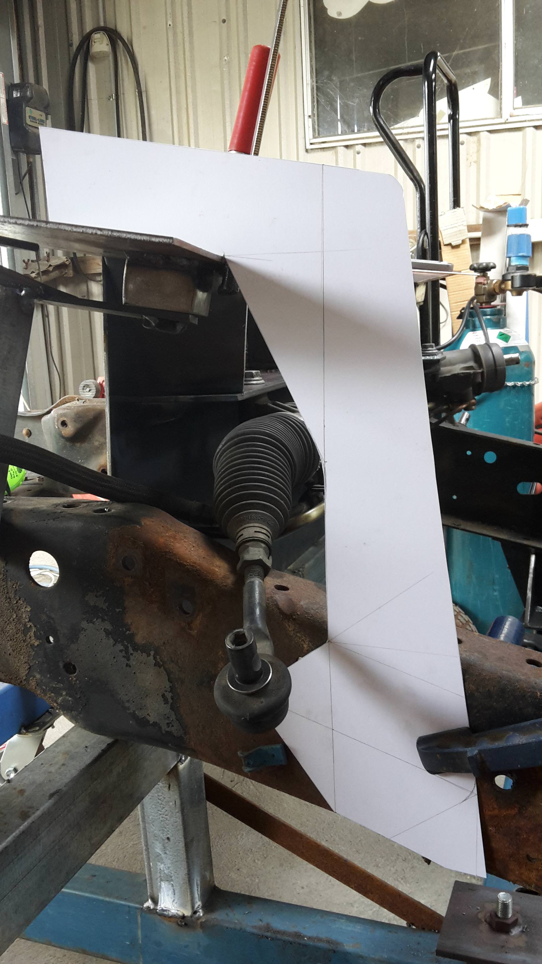
test fitted
perfect
and tacked in place.
I'll leave this like this for now and once the engine and cab is in its place, I'll check everything clears and fab a similar plate for the inside of the rail each side and box them in.
12-27-2017 #91
Registered User
- Join Date
- Dec 2014
- Posts
- 188
Cheers, Craig! Originally Posted by craigF
12-27-2017 #92
Registered User
- Join Date
- Aug 2008
- Location
- jacksonville,fl
- Posts
- 970
As much of a pain in the butt as it can be, I think I enjoy the engineering steps like what you're into right now as much as anything.
Probably need to give myself more credit now, didn't realize I was a cad design engineer all these years. Working on a cad design myself right now. Started fitting a 2016 z-06 rear bumper to my 83 el camino last year, need to cut the upper portion out & fabricate it into a functioning tailgate which will require special hinging geometry. that's where the cad design comes in.
12-27-2017 #93 Registered User
- Join Date
- Dec 2017
- Posts
- 61
Nice! I see the plasma cutter so I assume you used that to cut out the design but what are you using to guide it, and your stop and starts must be perfect as I really can't see any evidence.
1951 Ford F1, 1967 RS Camaro, 1979 Firebird Formula, 1979 Trans Am/LS swap.
12-27-2017 #94
Registered User
- Join Date
- Dec 2014
- Posts
- 188
I agree, I'm enjoying this so much more than I have all the rust and previous owner dodgy workmanship repairs that I've had to do on my 69. Hence another reason why it's taking forever, the motivation comes and goes on it. Originally Posted by jlcustomz
I usually work in my head then measure twice and cut once. Not always ideal though and at times causes a stuff up. A CAD template with a bunch of angles definitely makes life easier. It'll definitely help in your bumper project for sure.
Thanks! Originally Posted by FormTA
No, I only used the plasma on the tighter inner curve where the grinder couldn't reach cleanly. I then cleaned in up with a flap disc.
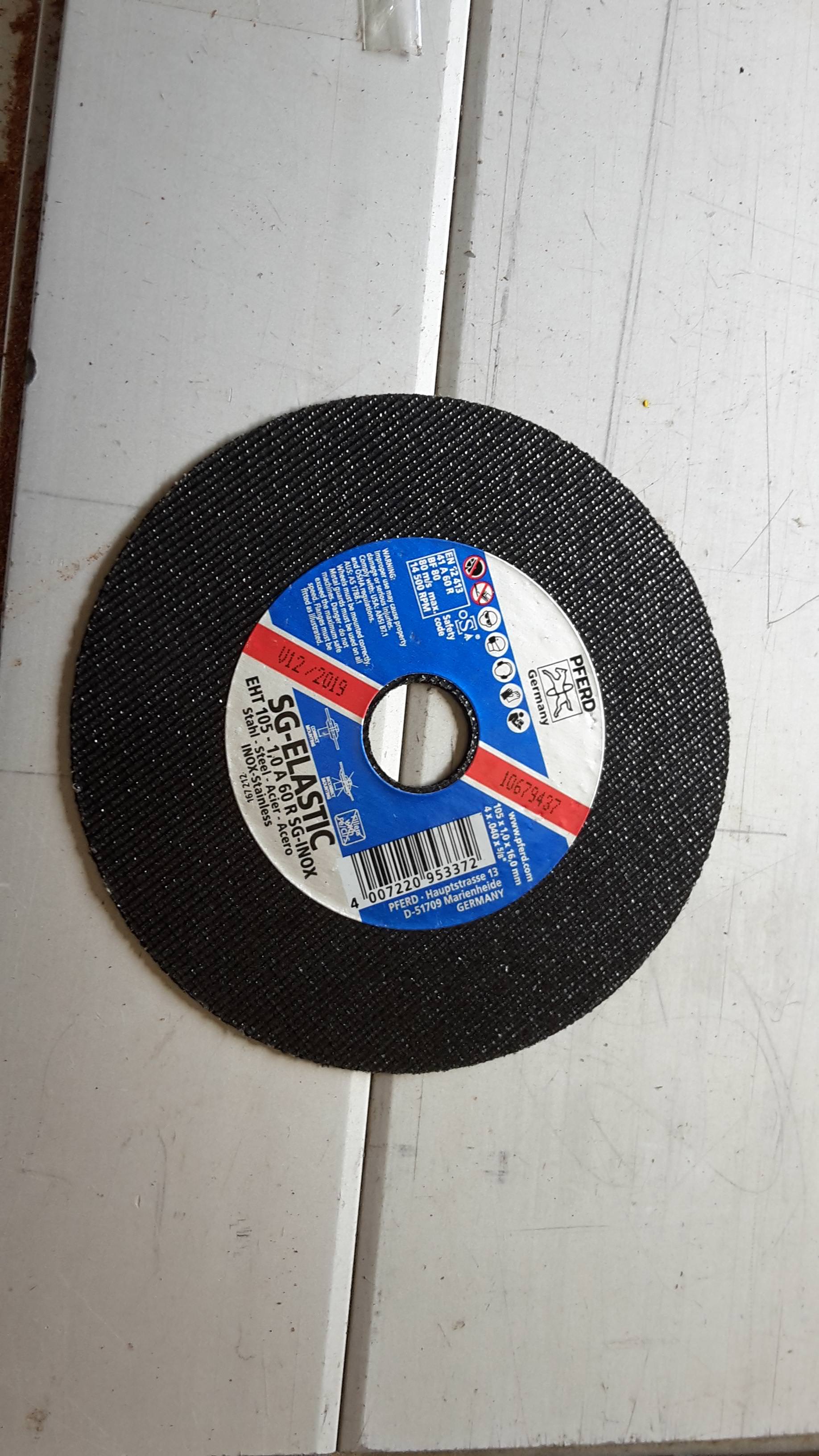
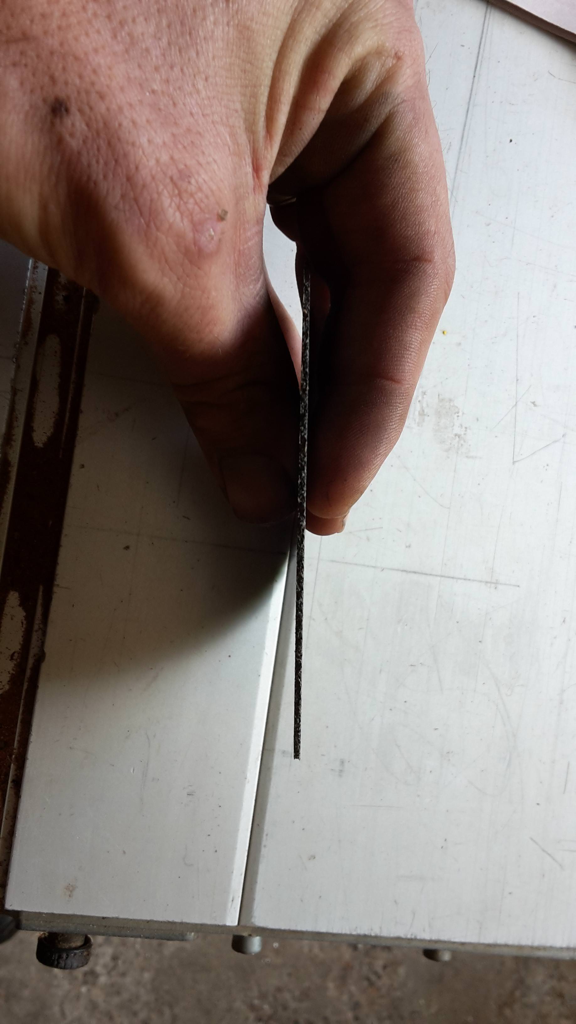
I've been using these thin cut off wheels for all my cuts on a 4" grinder. They are brilliant. They are very thin, cut quickly and precisely and take ages to wear down. After all these cuts on this project, I've only just started using a 3rd disc. At about $3 each, they are great value.
After cutting it out, a quick sand again with a flap disc is all that is needed to clean the cut.
12-27-2017 #95
Registered User
- Join Date
- Aug 2008
- Location
- jacksonville,fl
- Posts
- 970
Yep, a lot of people don't realize how the basic grinder with the right wheels can do so much work. One of the best wheels I've seen around here are the CGW stainless quickie wheels (camel grinding wheels) which I like in 6". https://www.aaabrasives.com/cgw-4501...b-flex-quickie One of the fastest & longest lasting I've tried. Huge difference over average wheels as zirconia is part of the abrasive, not just aluminum oxide. Not sure about that pferd wheel, but it's looks pretty damn serious too. https://www.pferdusa.com/products/20...6q010202P.html
Also found that a little more money on a more powerful variable speed 4 1/2" grinder such as Bosch along with a full face shield is a good investment for someone serious. With the variable speed I can more safely use the 6" wheels & dial the speed back up as they get smaller.
12-28-2017 #96
Registered User
- Join Date
- Dec 2014
- Posts
- 188
I find with these wheels that no pressure is really applied. Just let the weight of the grinder do the work and guide it along. If you force it, the wheel loads up and chews down quicker than usual.
The steel supply place I use stocks these and I think they are the only ones that do as they tell me they sell a lot of them.
And you're right, money spent on good tools is money well spent in the long run.
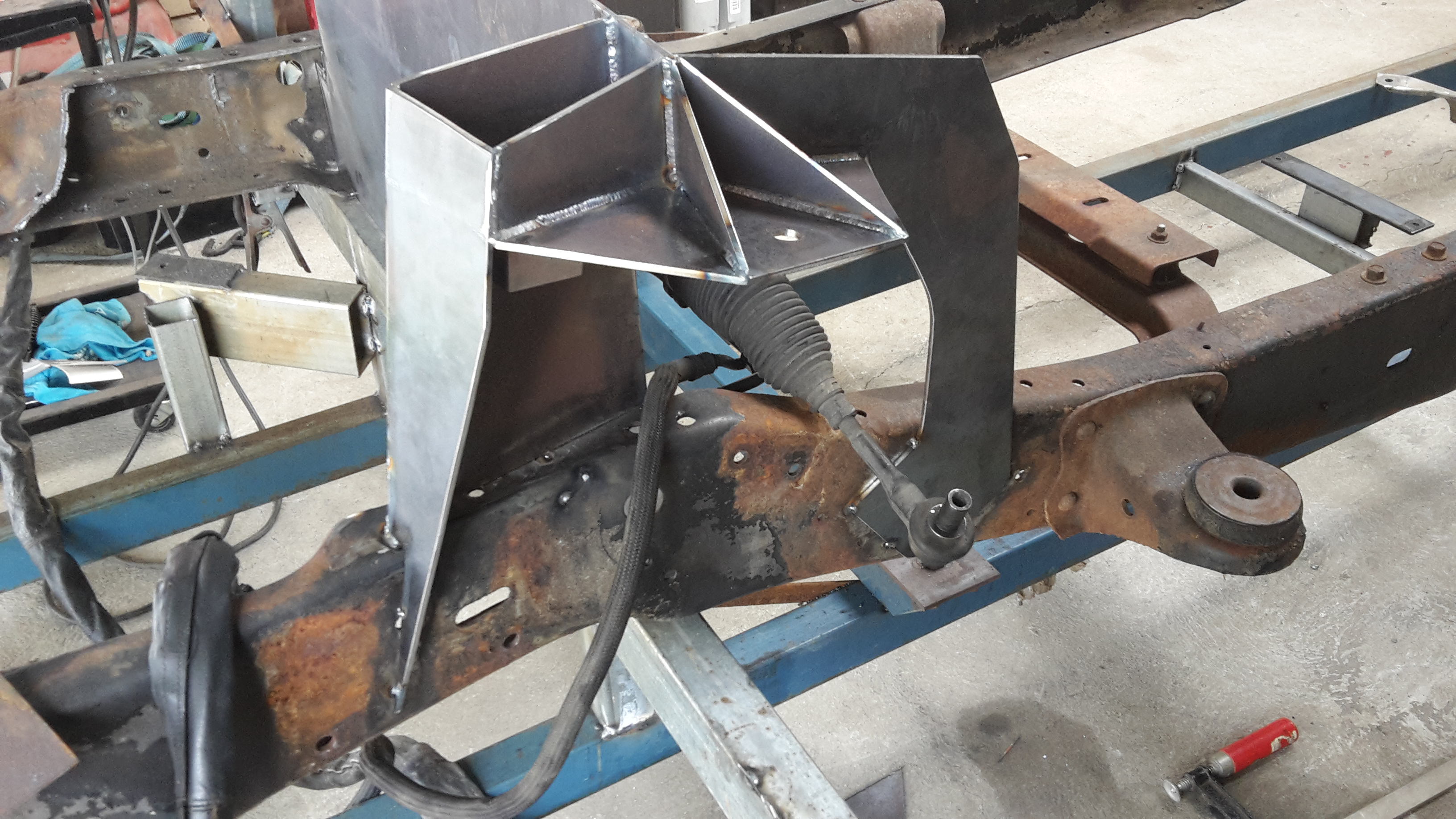
Here's the progression of what I got up to today.
and with that done, that part of the jig could now be removed. I still have some welds to complete and some webbing to add. Plus that rear section going over the rack and down to the chassis will eventually be boxed but for now I will leave it at this until the cab is mounted.
12-28-2017 #97
Registered User
- Join Date
- Dec 2017
- Posts
- 61
Thanks for the reply. I too use many grinders, one of which is dedicated to the slicer wheel. Your finished piece just looked so perfect. Thanks for the explanation.
1951 Ford F1, 1967 RS Camaro, 1979 Firebird Formula, 1979 Trans Am/LS swap.
12-28-2017 #98
Registered User
- Join Date
- Dec 2014
- Posts
- 188
My pleasure. And thanks for the compliment!
I did buy this little set of wheels for my plasma off ebay. It was less than $10. It did help to steady up my hand but getting it to arc was a bit of a pain. Even if I do get it to do a straight cut, it still needs a lot of cleaning with a flap disc. You also run the risk of slipping very easily and cutting inside your mark which then ruins it. I see some guys are quite good at it. I've only had limited use with mine. But it is a great tool for cutting up metal quickly.
12-28-2017 #99 Registered User
- Join Date
- Dec 2005
- Location
- Maryville, TN
- Posts
- 839
This is extremely fun to watch. Can't wait to see the cab on there!
12-28-2017 #100
Registered User
- Join Date
- Dec 2014
- Posts
- 188
Thanks, bald guy!

 Reply With Quote


