

Results 81 to 86 of 86
-
03-26-2016 #81

 Starting The Transformation
- Join Date
- Feb 2010
- Location
- El Segundo, CA
- Posts
- 268

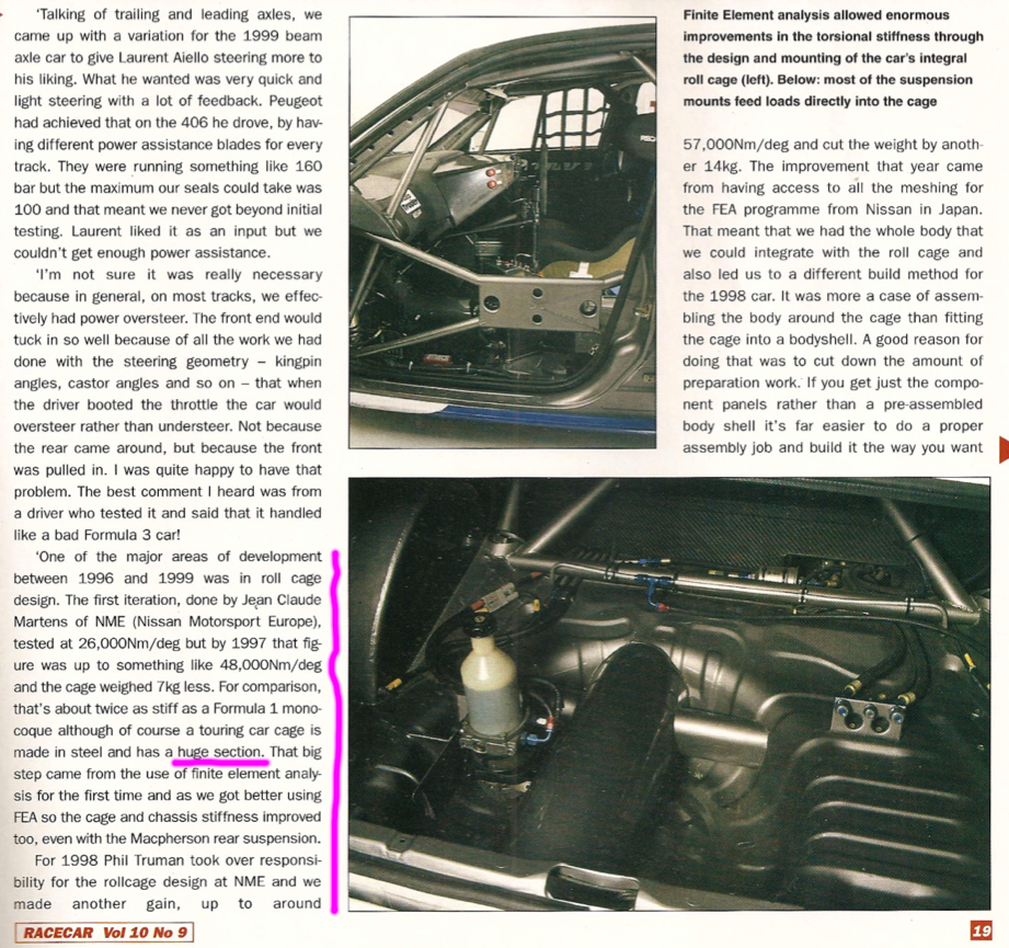
I was flipping through my archives and stumbled upon this article regarding a race car from the British Touring Car series back in the late 90's. This was a time during which great strides were made in how to use a roll cage to stiffen a vehicle in torsion. Before this time folks just thought of a roll cage in terms of crash protection. But the BTCC and World Touring guys in the 90's latched on to the idea that all these tubes, if properly placed, could make huge improvements in torsional rigidity. And that this in turn improves suspension performance. Just like there was a time when race car guys did not realize the benefit of wider tires, there was also a much longer period when they did not realize the importance of a rigid chassis in terms of getting a vehicle to handle. Automakers have likewise discovered that a stiff chassis is crucial to improving the all important NVH (noise-vibration-harshness) factor in passenger cars and trucks.
The article mentions the "section" of a car chassis relative to an F1 chassis. This bears directly on the statement I made that if you're building a pro touring truck frame, you should make it as wide and tall as possible. This increases its section (the size of a cross-section). A truck frame can be thought of as nothing more than a 'squat' roll cage or space frame.
See below if interested:
Gustave
-
04-07-2016 #82
 Registered User
- Join Date
- Nov 2010
- Location
- Ma.
- Posts
- 583
Let's discuss pinion angle. I was kind of hoping to set the engine at zero degrees ( parallel to ground ) what should the pinion be set at? should it also be at zero degrees? The only problem is that they will almost be in perfect alignment ( no angle ) so no rotation of the needle bearings. Any help would be appreciated.
-
04-08-2016 #83
 Registered User
- Join Date
- Aug 2010
- Location
- now In Dandridge, Tn.
- Posts
- 1,301
Well, having the crank parallel to the ground may be a nice thought, bu not too realistic. - It is do-able, but may not be the best bet - Most carb intakes have 2* to 4* of slope built into them, based on the OE settings, the carb was level, and the crank was at a slope. (down in the back) Even most EFI intakes are designed on the same idea. So to start with the eng and trans, once mounted, will probably lean back 2 or 3 degrees. BTW, oil pans, trans pans and headers are all built with this in mind. Having set the crank angle, start by setting the pinion parallel to the crank. Next, it's time to add in for what I call the 'pinion climb'. Under acceleration (and even a steady 60 mph is still considered accelerating against all of the drag forces against the car) there will be forces applied to the axle housing. The housing will want to rotate the opposite direction of the tire, and the pinion will want to rotate 'up' (if you are going forward). The type of suspension, tire compound, and engine torque will determined how far the pinion will be able to rotate. You want to counter act this, so that the pinion is parallel to the crank under normal load (70 mph freeway, where you don't want any vibrations).
As a general approach, I have this rule for pinion corrections. OE leafs -3*, Aftermarket leafs -2.5*, OE link -2*, aftermarket link w/poly ends -1.5*, Torque arms, trailing arms and aftermarket links with rod ends - 1*, competition only aggressive 3 and 4 links, - .5*.
This would be the degrees to push the front of the pinion 'down' from being parallel to the crank. The torque and suspension flex will then wind the pinion back up to parallel under load.
** This is NOT the way to do it for 4x4, crawlers, and dirt cars, they have there own rules.
** Way back in the day with the Nissan GTP cars, we set the pinion angle on the dyno, to get max torque (min power loss) at the typical corner exit through peak pull. We would spend hours doing it to get a 3 or 4 ft/lb advantage. That's how you win championships. It all adds up.
-
04-08-2016 #84
Registered User
- Join Date
- Nov 2010
- Location
- Ma.
- Posts
- 583
As usual, Thanks Rob.
So if I understand you correctly, if I set the intake at 0* the crank will probably be -2* to -3* down. And with the crank at -2* to -3* down , set the pinion at +2* to +3* up to make them parallel, minus the -1.5* down for my Fatbar suspension, equals +0.5* to +1.5* on the pinion. Correct?
-
04-10-2016 #85
Registered User
- Join Date
- Nov 2010
- Location
- Ma.
- Posts
- 583
How about side to side? My pinion is approx. 1" offset to the passengers side. Should the engine be offset 1" to compensate?
-
11-12-2016 #86
Registered User
- Join Date
- Oct 2012
- Posts
- 434
I asked Ron Sutton the same question once and he recommended moving the engine to help balance out the weight of the driver. 1" shift of a ~800lb drivetrain should help decently well plus you align everything. However, that's all based on if you have the room too!
-

 Reply With Quote


