Results 1 to 20 of 75
-
02-27-2013 #1

 Registered User
- Join Date
- Aug 2007
- Posts
- 612
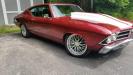
SPC Adjustable uppers Installed wrong. Snapped on street tires in the canyons.
This incident happened up near the rock store in Malibu.I was driving down the canyon when all of a sudden I felt a snap in the front end, and I could feel the wheel pull hard to the right. I could hear the tire squealing from the camber of the wheel. I was on very windy roads and was lucky enough to be able to steer it just off to the right into a pull off. 10 seconds earlier or later I would have ended up in the Canyon or into the side of the canyon.

I thought at first it may be a flat tire but quickly spotted the snapped plate on the SPC upper control arm. The car was exceptionally balanced and sorted before this incident and I would like to continue using SPC products but not at the cost of my life. I just wanted to warn others because I know many of us are running these control arms....
The car was exceptionally dialed in and sorted before this, and I'd like to continue using the adjustable uppers, but we will see how SPC handles the situation. I am running QA1 coilovers, hotchkiss sway bar, leafs, subframe connectors, guldstrand mod, wilwood W6 manual brakes.
Those with SPC arms, check them out before any spirited driving. Guldstrand told me that if you're not driving off the track or breaking something you're not going fast enough. I guess he was right but not at the cost of my life! I haven't had many close calls in this car but I have decided that its time to cage it and invest in some safety mods.
Be safe all!
Some artsy photos.
-
02-27-2013 #2
Registered User
- Join Date
- Nov 2005
- Posts
- 215

suscribed
02-27-2013 #3 Registered User
- Join Date
- Sep 2005
- Location
- Nor Cal
- Posts
- 2,196

Dane, that ain't cool!
What safety mods planned?1968 Camaro widebody project
2004 Mustang LS2
1964 Continental
2014 Keezer
02-27-2013 #4
Registered User
- Join Date
- Aug 2007
- Posts
- 612
Definitely was not cool. It got my adrenaline up which was fun, natural painkiller. Definitely a close call though. Originally Posted by Flash68

I need a Cage custom built behind the B-Pillar due to my height I sit just behind the B-Pillar with door bars. I need to find someone in the LA area who can hopefully build a cage with the interior in car because my interior is all original. Not sure if thats even possible.
I need a roll hoop, seatbelt crossbar, back into the trunk, and low door bars. I may even consider going all the way to the subframe just so I have some sort of rigidity. I've played with destiny too many times in this car and this was a wakeup call.
I'd also like to do a large fuel cell (6 mpg really sucks down that 16g stock tank quick!), yank the rear seat and carpet it like the old Flip down seat option.
Eventually maybe a fire system.
I've got enough health issues as is, I want to survive anything fate may throw at me.
02-27-2013 #5 Registered User
- Join Date
- Jun 2010
- Location
- Deployed
- Posts
- 3,280
Whats ironic is that's exactly why I sold mine. I bought a new set, had just a feeling they were not up to street/performance use. I was suspecting the threaded rods would rip from the aluminum. Sorry to hear your mis-fortune. Time for some tubular DSE or Hotchkis?
1970 Camaro/DSE build
Are you driver enough? Maybe....come on blue!
https://www.pro-touring.com/threads/...71#post1147371
02-27-2013 #6 Registered User
- Join Date
- May 2002
- Location
- Northern California
- Posts
- 10,716
You have to watch those fasteners. It comes with a 5/16" grade 5 bolt. I always open them up and add a 3/8" grade 8 fine threaded bolt and metal lock nut. Those are are track parts that get checked more so than a street car. Thank goodness you didn't go rubber up.
From the looks of the plate, the original nylock may have come loose (from stretch) and enlarged that hole. I have had a few come in with an egg shaped hole and a bent bolt. Is the bolt and broken section still on that link?MrQuick ΜΟΛ'ΩΝ ΛΑΒ'Ε
02-28-2013 #7 Registered User
- Join Date
- Mar 2009
- Location
- SoCal
- Posts
- 1,240
Upper control arms deal with forces along two basic axes. The first and primary direction of force is simple compression/tension along the arm (and by resisting these forces it maintains the wheel's camber angle.) The SPC arm should be just fine for taking these loads that only amount to a couple of hundred pounds.
The second, deals with the front to rear motion (which is sort of a resistance to caster change.) The SPC arms, along with many tubular control arms, have no extra support tube and are just open on the wide end. Combine this with the Camaro cross shaft that only traps one side of each of the arm mounting points and then you can see that any forward force must be resisted by the front mounting point and any rearward force must be resisted by the rear mounting point. Any force not dealt with at the mounting point results in an increased twisting force on the arm and it is up to the strength and stiffness of the arm itself to maintain its basic shape.
To clarify, the only real resistance to movement along the cross shaft on the Camaro style cross shaft is the nut. On the opposite side of the same bushing, there is no real resistance. The torque from the misaligned forces is now just focused around on point instead of two.
If you're wondering about the 3rd dimension, the upper control arm does not resist motion in that case. That is handled by the lower control arm and spring; the upper control arm is just along for the ride in that direction.
There are two basic solutions to prevent this problem.
1. Run an upper control arm that has the extra support tube toward the wide end.
2. Trap each cross shaft pivot on both sides instead of just one.
Either of these will reduce the flexing on the arm a great deal. Reducing this stress and deformation also helps the arm contend with the load it takes in the other direction.Brett H.
1979 Pontiac Firebird Trans Am
1991 Mazda Miata
2005 Ford Mustang GT
1987 Ford Mustang GT - Sold 06-29-2014
1988 Oldsmobile Cutlass Ciera - RIP 9-17-2011
1992 Chevrolet Corvette - Sold 10-12-2017
02-28-2013 #8
Registered User
- Join Date
- Sep 2004
- Location
- savannah,ga
- Posts
- 862
Hi Rogue, I've followed your car here for a long time, really cool. What is your plan for upper arms now? I ask because I am using the same arm and I have wondered about this, my car isnt driveable yet so I have no personal experience. I am also interested in the lugnuts you have, did those come with the PSE wheels?
02-28-2013 #9
Full Blown G-Machiner
- Join Date
- Sep 2004
- Location
- PA.
- Posts
- 935
Hi Rogue, bummer about your UCA. I see a number if issues that you may want to attend to before you repair and drive the car again. First off the breakage was caused by vertical binding, flexing the ball joint plate until it fatigued and snapped off. This is the mode of failure that produces those results in destructive testing. The arm was probably contacting the frame in droop long before it reached full travel. There is a small witness mark in photo 1. There are a couple causes for this.
*First off, the arms are installed UPSIDE DOWN*.
The vertically offset pivots that normally add a lot of droop clearance are now dramatically restricting it. Flip the cross shafts over to fix this. Second, we only sell these A arms for configurations using taller ball joints or tall spindles, this also adds more clearance in droop and it zeros out the mounting angle of the ball joints at ride height. It appears you are using stock height ball joints and spindles. There`s no geometry correction like that so it would be a big improvement to upgrade.
To add insult to injury you`re running the Guldstrand mod, which yields another huge reduction in droop travel! The car must have hardly any droop travel at all.
Rogue, I know you didn`t buy the arms from us because they`re in a configuration we don`t sell but please give me a call and I`ll be happy to talk you through the application and work with you and SPC to get the proper setup on your car. I promise you that when they`re configured and installed properly they are extremely durable and work fantastic.
To Mr Quick. You must be remembering some other brand of A arms. I agree 5/16" bolts would be much too weak BUT SPC A arms have and have always had 7/16" bolts, even larger than the 3/8" bolts you`ve had to upgrade other A arms to. They`re much stronger than they need to be for the application and we have never seen any issues with them at all even after tens of thousands of hard test,track and all weather street miles.
To 79-TA , nice diagrams but technically incorrect. Your assertions might be true of these were H arms but they`re not, they`re A arms. Triangles are non compressible, they do not wrack. So maintaining their shape they do spread thrust loads to both bushings, one on the thrust washer and nut and the other on the shoulder on the cross shaft. Thus there`s no need to extra support tubes. I once argued your point as well but a seasoned suspension engineer showed me the error of my ways. Note that C5 / C6 Corvettes, new Ferraris, Vipers and for that matter Formula 1 cars have no "extra support tubes" either.
Last edited by Marcus SC&C; 02-28-2013 at 09:38 AM.
02-28-2013 #10
New to Pro-Touring
- Join Date
- Jul 2007
- Posts
- 1
hmpf, can't see any pics in Post #1.
02-28-2013 #11
Registered User
- Join Date
- Oct 2006
- Location
- Chicago
- Posts
- 289
I don't agree with your second sketch and assumption. Force applied to the upper ball joint area along the vehicle longitudinal axis (X-direction from SAE coordinate system IIRC), will also create tension/compression forces in the upper A-arm. This does not solely create a sliding effect on the A-arm cross shaft as you have sketched. If you draw any freebody diagram, forces applied off a centroid will generate both shear and moment reactions. You have the shear component described, but neglect the moment that will want to make the A-arm rotate around its centroid. You'll have tension/compression in the A-arm members, which will result in forces being applied to the cross-shaft that are normal (perpendicular) to its centerline. Originally Posted by 79-TA
Rogue, sorry to hear about your problem. That really sucks. I'm running these on my car as well, so I am watching this with great interest.Luke
'63 Chevy II wagon - project
02-28-2013 #12 Registered User
- Join Date
- Apr 2011
- Location
- North NJ/SW Virginia
- Posts
- 197
subscribed
02-28-2013 #13 Registered User
- Join Date
- Mar 2009
- Location
- SoCal
- Posts
- 101
Sorry to hear about your misfortune, you were very lucky not to be hurt or damage that beautiful car.
Are those PS Engineering wheels?
02-28-2013 #14 Registered User
- Join Date
- Jul 2012
- Location
- Traverse City, MI
- Posts
- 574
I learned more reading Marcus's post than I have using the search function and reading threads the entire time Ive been on this website. Originally Posted by Marcus SC&C
Brohug - :nohomo:
02-28-2013 #15
Registered User
- Join Date
- Nov 2005
- Posts
- 215
Superb tech. I have spoken with Marcus on the phone at length and he is quite knowledgeable in these unfortunate circumstances.
02-28-2013 #16 Registered User
- Join Date
- Nov 2008
- Location
- Lawrenceburg, TN
- Posts
- 4,086
watching this
02-28-2013 #17
Registered User
- Join Date
- Mar 2008
- Posts
- 952
so these were installed wrong: do they come with instructions or have any kinds of markings on them to show how they are supposed to be installed?
03-01-2013 #18 Registered User
- Join Date
- Oct 2004
- Posts
- 419
If someone doesn't read the whole thread the title might be a little mis-leading.
03-01-2013 #19 Registered User
- Join Date
- Apr 2009
- Location
- san diego
- Posts
- 5,102
same here Originally Posted by Rod
My build thread: https://www.pro-touring.com/showthre...ing&highlight=
The mustang build thread: https://www.pro-touring.com/showthre...el)&highlight=
03-01-2013 #20
Registered User
- Join Date
- Jan 2008
- Location
- SC
- Posts
- 495
Marcus, just curious, how do you mount a droop stop with those style a-arms? I wouldn't want to rely on the shocks end of stroke.
I run a bolt through upper a-arms that have the hole for the rubber stop so I can adjust it, for just this reason.

 Reply With Quote