

Results 1 to 20 of 30
Thread: EFI Mopar project
-
12-29-2009 #1

 Registered User
- Join Date
- Jan 2009
- Posts
- 197
EFI Mopar project
Hey guys I have posted this on another site so I'm going to post it here because I think it is a better site for this kind of thing.
As you may know from other posts, I'm working on doing an EFI conversion for my 360 powered 1967 Belvedere. Although this will be focused on the small block conversion, the information here will apply to anybody wanting to convert their combustion engine to fuel injection.
Let me give a little background for myself. I went to Georiga Institute of Technology to get a degree in Mechanical Engineering, and my passion is in automobiles. While I was there I joined a team called GT Motorsports (http://www.gtms.gatech.edu/). The object of this team was to build a car from scratch to compete in design, autocross, and skidpad events. These cars are seriously fast. They typically employ high end motorcycle engines, and weigh in under 500 lbs. The car we built had 1.2g+ engine acceleration and 2g+ in braking/cornering. Of course we bought what we could, but for the most part, the car was designed and built from scratch, including the chassis/wheels/suspension/intake systems/bodywork/brakes...as much as possible. I was the powertrain leader while I was there (not a very successful PT engineer :P), and during my tenure, I learned quite a lot about intake and exhaust systems, and also a good bit about cooling systems. It really was the stuff of dreams...we made stuff from scratch using carbon fiber like it was scrap metal. At any rate, this ties into this post because the car employed a custom EFI system, and I acquired some experience tuning this car using the system that we had (a pricey motech m800 ecu and a custom carbon fiber intake that we designed).
My Plymouth will be much more modest (as is my budget...I don't have 100K to spend on a toy race car!). My goals for this project:
Fully adjustable fuel injection/ignition control system for under $1500.
(edit: I've already blown the budget I think) It could easily be done for less than that but I'm picky about certain things (I'll get into that later).
System must have upgrade potential (turbochargers anyone?)
I want to be able to start the car, on a cold winter day, with no fuss. Honda Civic style no-fuss.
The system must fit under the stock hood. I don't want a scoop. If I had a Hemi or a really rad 440 I might consider a six-pack style scoop like the silver bullet gtx but, well, I have a small block.
(edit: I don't think my setup will fit under the hood...we will see)
Increased mpg would be a nice bonus...but it's not a primary concern.
Instead of using the latest greatest megabucks fuel injection kit I'm going to employ the Megasquirt (www.msefi.com) for my controller. The plus side is that it costs about $250 for the controller...the downside is that you have to assemble everything yourself (As we speak I'm finding this to be not terribly difficult). If you are going to embark upon such a project you will have to learn everything there is to know about EFI systems. This system won't tune itself like the $3K+ Edelbrock system. That's the only downside. The plus side is that there really is no limitation on what combinations you can employ or how much power you can develop. You can put a megasquirt on a weed eater (hey...it might be fun!) or a 16000 rpm V-12...basically any engine that burns combustible fuel can run this system.
Let me give a few basic details of my car...
It's a heavy as hell Belvedere with a 360. I probably should have gone with a big block from the start but I'm far too invested already with the sb, and I have a borderline sick obsession with creating a fast sb powered b-body. Can it be done? I think so.
M1 single plane intake with a 750cfm carb
It has a mopar purple shaft cam...I can't remember the duration specs right off hand but it is the .474 lift hydraulic cam. It doesn't sound hot enough for my taste.
Comp anti-pump lifters
KB flat tops near zero deck yielding 10.6 compression
302 casting heads with 2.02/1.6 valves and heavy heavy porting
Eagle I-beam rods
A few other details which aren't worth mentioning.
Low end torque is non-existant...but then that wasn't my goal with the car from the start! I think the intake choice was probably not a wise one, but as you can tell at this point I'm not so worried about it.
The major parts I have acquired thus far:
Weiand Hi-Ram tunnel ram. I'll be using the lower portion of the intake for the EFI conversion, and fabricating the EFI plenum. As before, this intake isn't so much geared for low rpm torque but that is not what I'm aiming for at this point with my project.
Infinity Q45 throttle body. This is a very nice piece, and they are all over ebay for under $100. I got mine for $60 with shipping. It has a bore of about 3.5". It will flow more than enough for a NA 360 in this state of tune, or really anything naturally aspirated up to 500hp or so.
30lb/hr bosch injectors
Megasquirt MS-II EFI computer, Megasquirt Stimulator, 3bar map sensor, wiring harness
Bungs for the fuel injectors
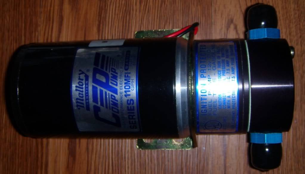
fuel pump (Mallory 110 gph EFI pump)
I didn't just buy parts listed above at random...I'll be going into more detail on that later.
Stay tuned!
-
12-29-2009 #2
Registered User
- Join Date
- Jan 2009
- Posts
- 197
Post 2:
After a long break I am back and have made some decent progress on the EFI conversion. Sorry I took so long to continue, but my job requires quite a bit of travel, and I have to go to SE Asia for a few weeks and also a couple of domestic trips, and quite frankly, my job takes precedence!
So at any rate I wanted to update things that I have been working on.
-Almost finished with megasquirt assembly
-Completed work on adapter plate for plenum
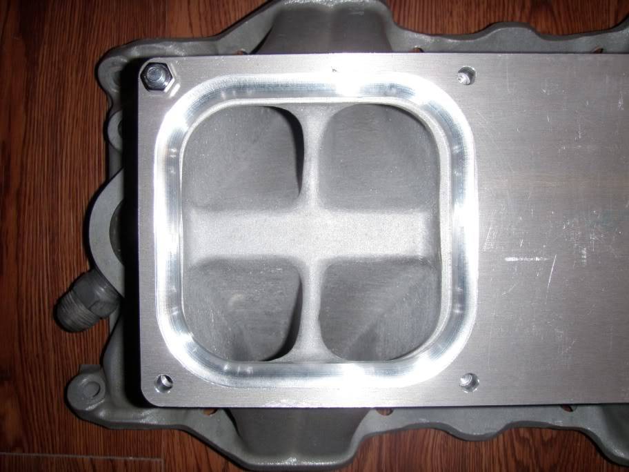
I have attached some pics of the new (simplified) design for the intake, one showing the plenum design and one with the plenum and TB hidden so you can see the adapter design. I also posted a couple of pics of the adapter plate I got in from the machine shop yesterday. Later on I will also upload some pics of the megasquirt assembly process and of course at some point write some of my design notes.
By the way the adapter plate cost me $100 from the local machine shop, to give you an idea of costs involved. Honestly the most expensive thing with such a project is time, and the time spent in design is considerable. I'll talk about more of the design later on.
12-29-2009 #3
Registered User
- Join Date
- Jan 2009
- Posts
- 197
Post 3:
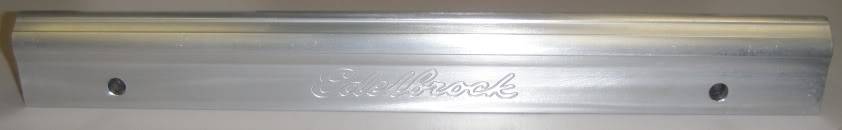
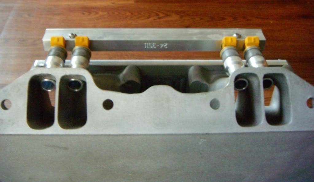
o I have been working with my machine shop and also I received some parts today from Summit. The pieces I got are some of Edelbrock's fuel rails for the LA small block, and boy am I happy about these! They fit standard style Bosch injectors, are tapped both ends (3/8" npt), and happen to look pretty sweet. They're $100 and change, which is less than having them custom made would be. If you have them custom made, you have to purchase the extrusion here: ( http://www.rossmachineracing.com/dash8.html ). It is $11/ft, and you have a minimum 2' purchase. I figure you would probably want to get 3' just to be safe, so to have them custom built you would have to spend $30 on the extrustions and then easily $100 to have a machine shop make the appropriate cuts. So $100 is a good buy for some pre made rails!
I posted a few pics of the rails:
Here's an overall view:
Here's a shot of the fuel injector bores:
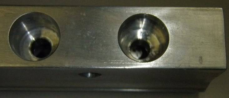
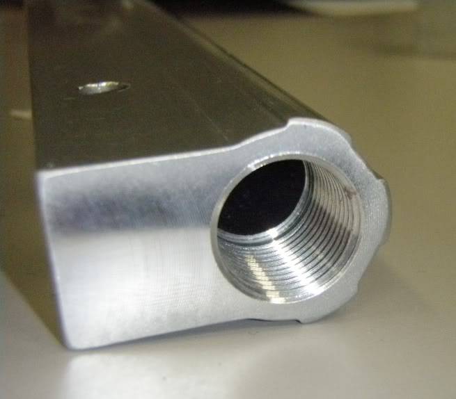
Here's a shot of the npt taps:
Here's the "bling" shot:
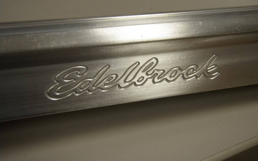
These are clearly nicely made pieces. I'm very happy with them.
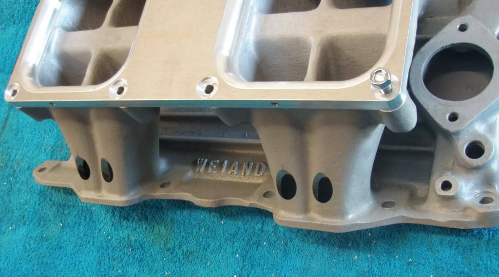
I also wanted to show you the fit of the base plate for the plenum...I'll need to do some die grinding on the casting to match everything up:
I'll post some pics up of the finalized design for the top soon...
12-29-2009 #4
Registered User
- Join Date
- Jan 2009
- Posts
- 197
Post 4:
Hey guys just to give a quick update, I have finalized the design of the tunnel ram top for EFI, with the exception of the throttle body mounting provision. I would like to place a 90 deg elbow in between the throttle body and the plenum to try to calm down transient turbulence caused by opening throttle butterflies. It is actually quite severe, and I would like to give the air flow a chance to straighten out before it has to make the turn down on the front half of the motor.
All the drawings for the parts are currently at the machine shop. They will be making the sheet metal portion and also boring holes in the runners to install the injector bungs into. Everything is made from 6061 aluminum except for the sheet metal part, which is made from 3000 series aluminum. 6061 doesn't like to be bent, but 3000 series stuff is fine with it. They are weld compatible, something you have to look out for on aluminum parts. Some of the stuff can't be welded at all. The tubes are from mcmaster, and the screws will drop down inside of these tubes.
The calculated weight for the top is 2.9 lbs (much lighter than the original top), and the volume is about 480 cubic inches. This will be plenty of volume for the 360 or the 408 should I decide to stroke it.
Well let me know what you guys think and I'll post some pics of the finished parts.
12-29-2009 #5
Registered User
- Join Date
- Jan 2009
- Posts
- 197
Post 5:
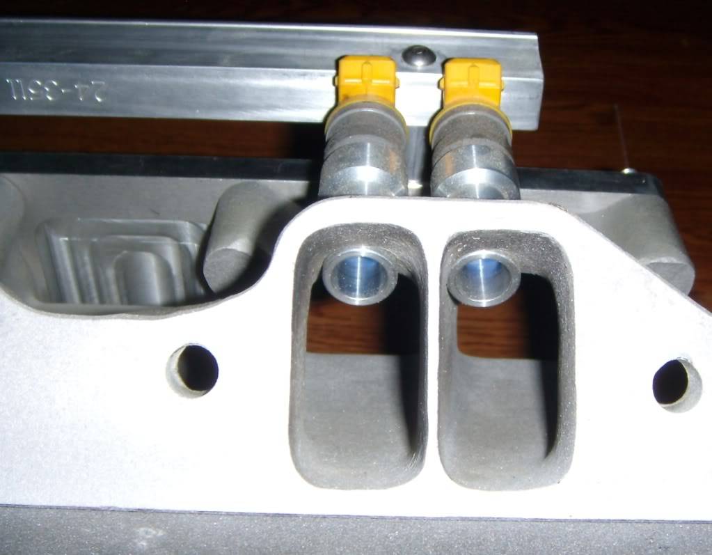
I just got back from the machine shop. I had to discuss with the machinists how I wanted the sheet metal top to be bent, and while I was there I took some pics of the progress they have made. At this point, the sheet metal has been cut out and is now ready to be bent into shape, and the tunnel ram base has been bored for the injector bungs and is ready for welding. After talking with the machinist we decided it would be best to have the bungs welded into place. Also, I can't remember if I mentioned this earlier, but the sheet metal portion is made from 3000 series aluminum, as 6061 will develop cracks on the surface when you try to bend it. The problem with 3000 series stuff is that it doesn't accept anodizing very well, so that is something to consider. I think I'll have everything powdercoated in the end so I'm not too concerned about that. At any rate, the work is looking fantastic and I am very happy with how everything looks! I particularly like the way I decided to mount the rails to the plenum base...it is very clean and will be very robust also. Here's a few pics for you guys:
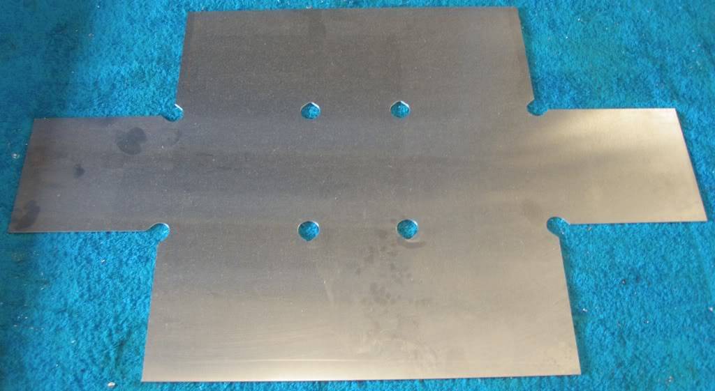
Sheet metal top before bending:
Bores milled into intake to accept injector bungs:
How the injector arrangement looks on the tunnel ram base:
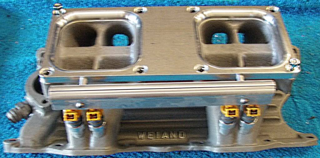
Detail View of fuel rail mounting arrangement:
12-29-2009 #6
Registered User
- Join Date
- Jan 2009
- Posts
- 197
Post 6:
know it's been a while since I updated this, mostly its because I have had to travel so much lately for work and I haven't been pushing the machinists to finish things up.
They have bent the top and also have cut the tubes (screws will drop into the tubes). At any rate its starting to look pretty damn sweet and now I'm shopping for a welding shop to weld it all up for me.
I took more pics to share with you guys.
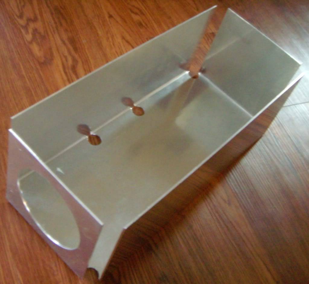
Here's the lid bent into shape:
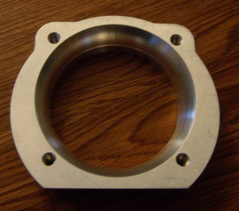
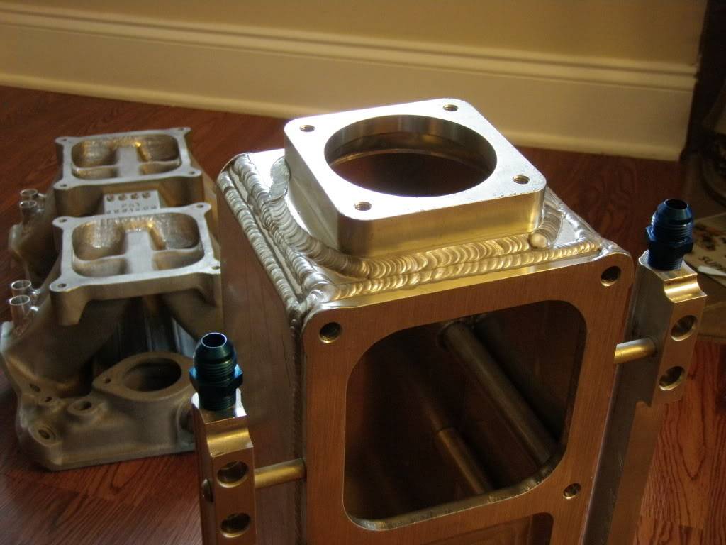
Here's the adapter for the Q45 throttle body (this is an off the shelf piece)
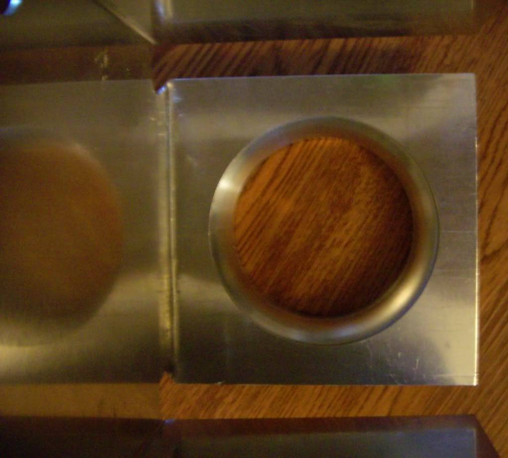
This is the view from inside the plenum lid at the throttle body adapter:
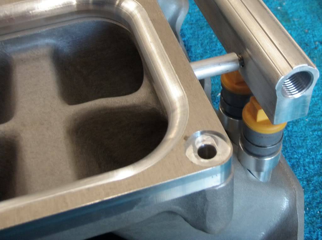
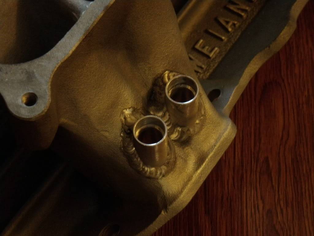
This is the view from the intake flange showing the alignment (or lack thereof) of the injectors:
An upclose of the injector alignment (of course I plan to smooth the bosses down once they are welded in):
A view inside the plenum from the throttle body perspective:
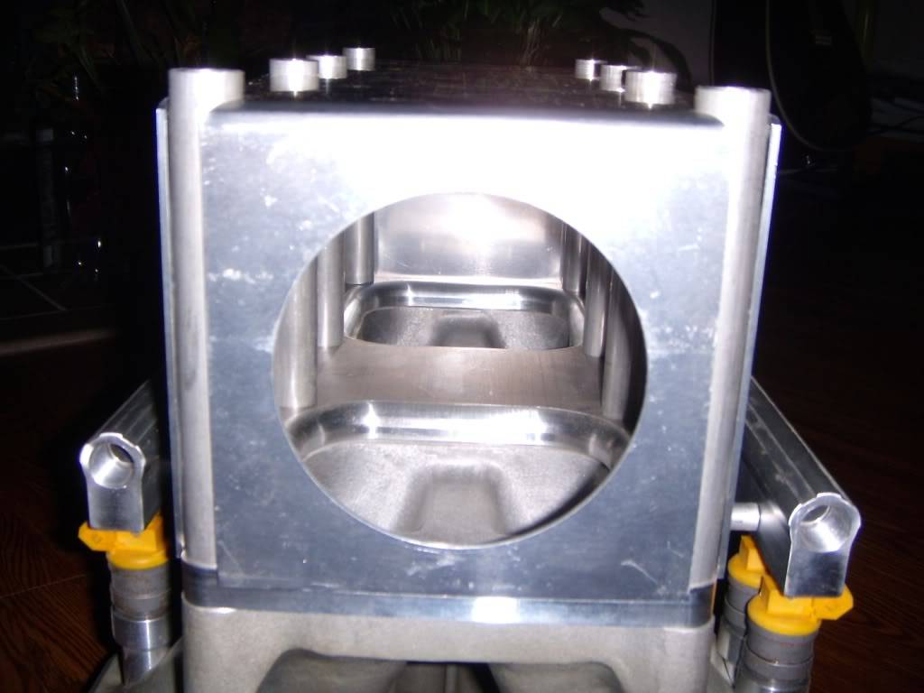
An overall view of the intake prior to welding:
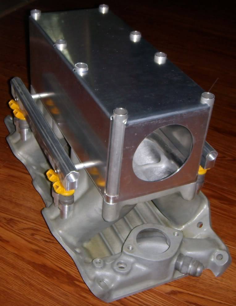
Once everything is welded up I'll grind down the excess material from the tubes on top of the plenum. All that will remain at that point is adding a couple of bungs for the MAP (manifold absolute pressure) and the IAT (intake air temperature) sensors. And of course some provision for N2O still needs to be added.
12-29-2009 #7
Registered User
- Join Date
- Jan 2009
- Posts
- 197
Post 7:
More pics...
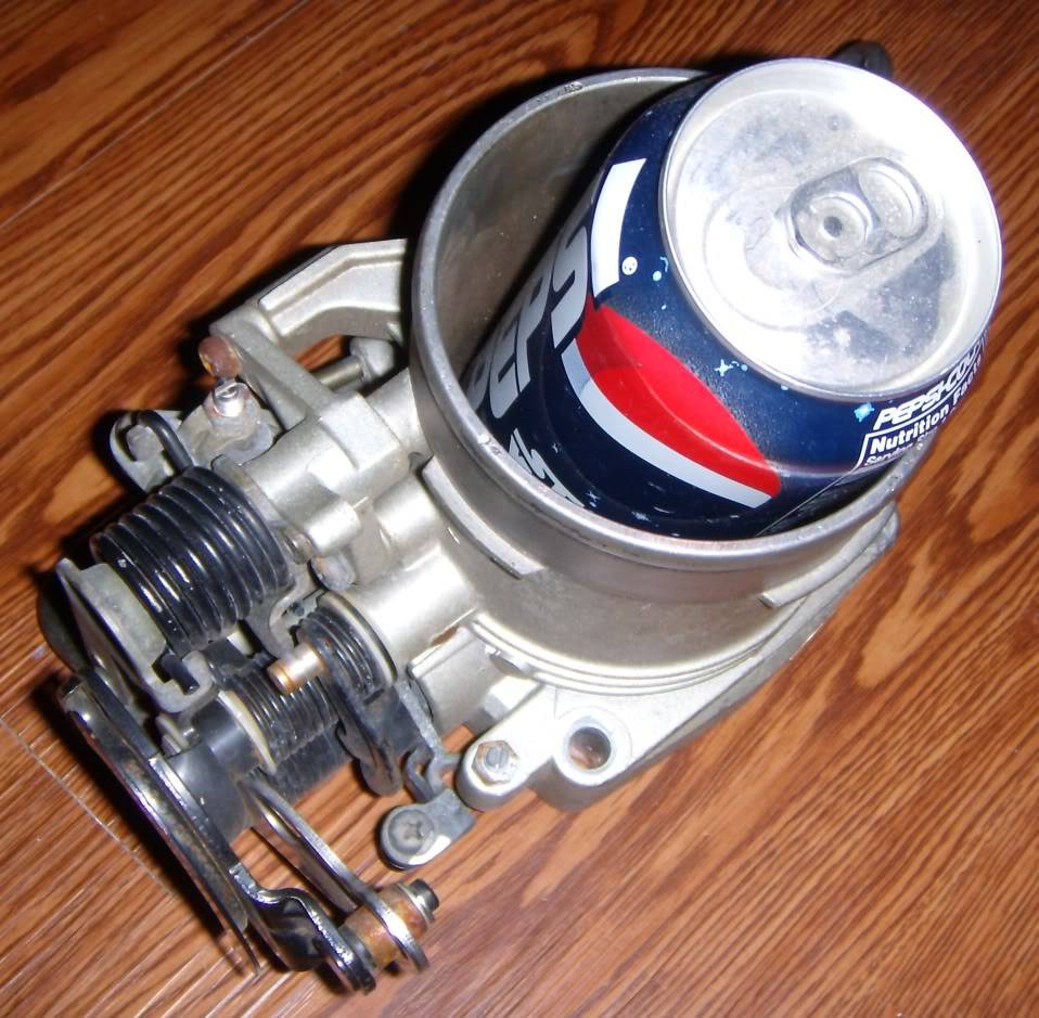
The Q45 90mm throttle body:
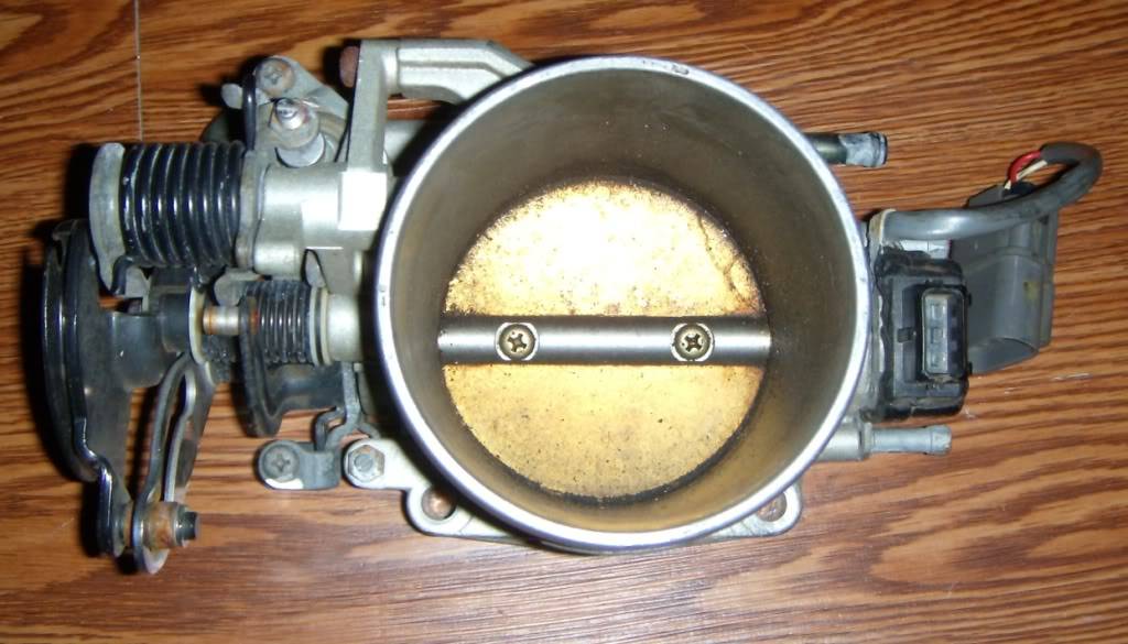
This is a big throttle body...just for some perspective:
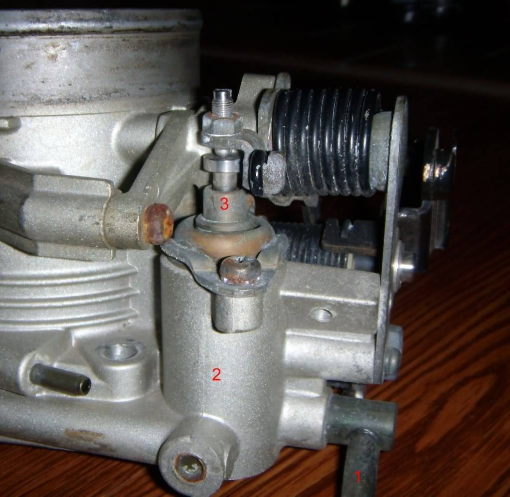
This unit has an ingenious cold idle system; its purely mechanical. I've labeled the picture with numbers to illustrate. This really is my favorite feature of this unit. Hot water flows into "1", heats up the chamber "2", and causes the plunger "3" to extend, which slightly closes the throttle blades. With this system (which Infinity had the wisdom to make adjustable) I should be able to have the cold idle tuned nicely without any kind of solenoids or other electronic idle control features.
The totally sweet fuel pump I scored on ebay for less than half price:
12-29-2009 #8
Registered User
- Join Date
- Jan 2009
- Posts
- 197
Well that's all for now guys.
I am finalizing a couple of things before I send the setup off to the guy who is going to weld it up. Basically I am trying to decide what method I am going to employ to plumb in the N2O, and also I need to fabricate up a mounting provision for the throttle cable, then I'll send it. I'll post updates as I get them.
01-01-2010 #9
Registered User
- Join Date
- Dec 2008
- Location
- Lehigh Valley Pa
- Posts
- 1,269
Very cool intake. Can't wait to see it done.
1996 Federal Cadillac hearse
1988 Eureka Chevy hearse
01-02-2010 #10
Registered User
- Join Date
- Apr 2005
- Location
- Colorado Springs
- Posts
- 760
How did you determine the plenum volume?
TonyC@HP2
01-08-2010 #11
Registered User
- Join Date
- Jan 2009
- Posts
- 197
I went through several iterations on the plenum design. In the beginning I wanted some sort of side-entry design, mostly to avoid cylinder to cylinder air distribution problems. Looking at these designs, however, I came to the realization that it would be very pricey and difficult to fabricate something with so many pieces. I wish I could tell you I did something very fancy like a 3D fluent model but that just isn't the case. In the end the design of the plenum was mostly dictated by ease of construction and the diameter of the bell-mouth on the throttle body adapter. The calculated volume comes out to about 450in^3. A rule of thumb I have heard is that the plenum should be the size of the engine or greater, although I have found no data to conclusively back that claim up. I will at some point build a 408 stroker out of my engine, and I might go with forced induction at that point, so 450 in^3 probably isn't too bad of a starting point. In my opinion it is better to err on the large side with a plenum because when you start reducing the volume the design of the plenum becomes more critical; you could easily choke some cylinders if it doesn't flow well enough.
05-22-2010 #12 Registered User
- Join Date
- Apr 2008
- Location
- Lakeland, FL
- Posts
- 516

Very cool thread! i think that this has inspired me to take the first step towards fuel injection. I have a few questions for you though: First, do you have any updates on this project? Secondly have you gotten into programming anything onto the board yet, is it 'difficult'? And finally what do you need from MS for this to work, is it just the "MegaSquirt-II Engine Management System w/PCB3" kit? ..i just dont know what components you need to get from MS for a stand alone fuel system to properly operate. I love the potential for tunability and adaptability from this system and want to gain as much insight before i take the plunge completely.. Keep up the good work, good luck, and thanks for any advice/insight you can (and already have) provide(d)!
Tim
71' Demon-408, efi, 'viper spec' T56, Dana 60 w/ triangulated 4 link
05-26-2010 #13
Registered User
- Join Date
- Jan 2009
- Posts
- 197
Sorry for the late response.
you should definitely check out http://www.msefi.com/index.php
they have tons of information on that site.
What do you need?
MSII controller, harness, and sensors (most of which can be purchased here: http://diyautotune.com/)
You need an EFI manifold or will need to adapt a carb manifold, there are many options for this. Edelbrock even makes an EFI manifold and fuel rails (I used the fuel rails).
You will need a throttle body.
You will need injectors, a high pressure fuel pump, pressure regulator, and some way of returning unused fuel back to the tank.
Of course, this list isn't comprehensive. The megasquirt is definitely not a stand alone system, but it is adaptable to just about any imaginable configuration.Sean
05-27-2010 #14
Registered User
- Join Date
- Apr 2008
- Location
- Lakeland, FL
- Posts
- 516
Thanks for the reply, i was assuming all of those misc. items needed, but as far as megasquirt stuff theres the MS II and the stimulator kits, would you need both? ..i just opened an account on the MS forums, ill poke around there some too. Keep us posted whenever youve got an update, good luck again!
Tim
71' Demon-408, efi, 'viper spec' T56, Dana 60 w/ triangulated 4 link
05-27-2010 #15
Registered User
- Join Date
- Jan 2009
- Posts
- 197
The stim is basically a setup which mimics sensor inputs from the engine. There are basically a handful of dials which give the megasquirt inputs like rpm, manifold pressure, engine temperature, etc. You plug this into the megasquirt to bench test it to make sure it is working before you proceed with trying it on the car. Is it absolutely necessary? Probably not. However, if anything is wired up incorrectly it is better to diagnose it while the box is still on the table.
I would say I spent four evenings after work putting it together, working on it for four hours a night. It wasn't too bad honestly. Considering the cost and versatility of the unit it is totally worth the effort of doing the soldering. Plus, this way if something ever goes wrong with the unit you are capable of fixing it yourself (try that with a stand alone kit!)Sean
06-09-2010 #16
Registered User
- Join Date
- Jan 2009
- Posts
- 197
Hey guys...quick question
Where is the best place to run the MAP sensor hose to? My main concern is that I want to minimize MAP fluctuations caused by cam overlap and reversion in general.
I think there is a place on the throttle body, one of the nipple fittings just after the butterfly could be used. This would certainly be the easiest route.
Would it be better to place the MAP sensor hose attached somewhere in the plenum? I have a couple of options if I attach the nipple fitting to the plenum:
1) weld a bung in the side of the sheetmetal portion. If I go this route where is the best place to place the bung?
2) I can drill and tap the base flange from the underside with npt threads and screw the bung in directly. This hole would be located centrally in between the two large openings in the base flange. I kind of like this option because it will lend a somewhat cleaner appearance; the hose would route into the open area under the runners.
By the way I'm finally sending the intake out next week to be welded up.Sean
06-21-2010 #17
Registered User
- Join Date
- Jan 2009
- Posts
- 197
Hey guys sorry for the long delay on this.
I sent the intake out last week to (finally!) get the thing welded up.
As soon as I get that back I'll post up some picutres.
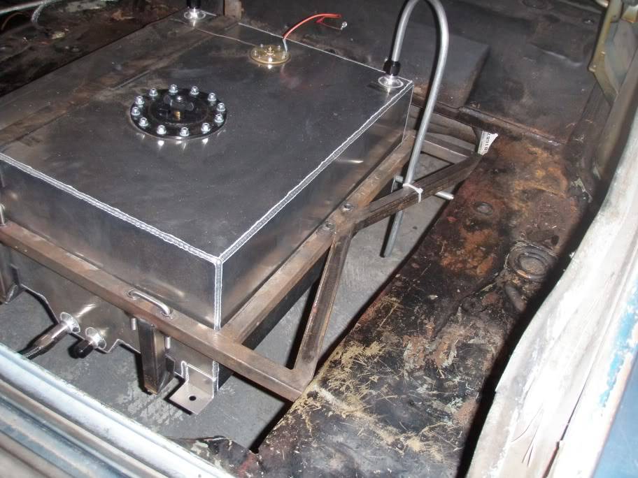
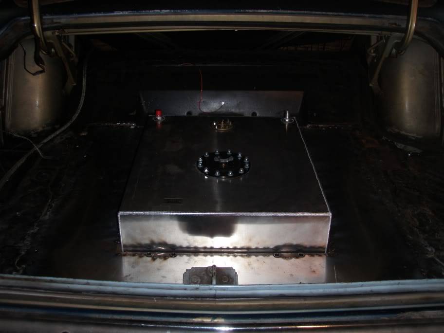
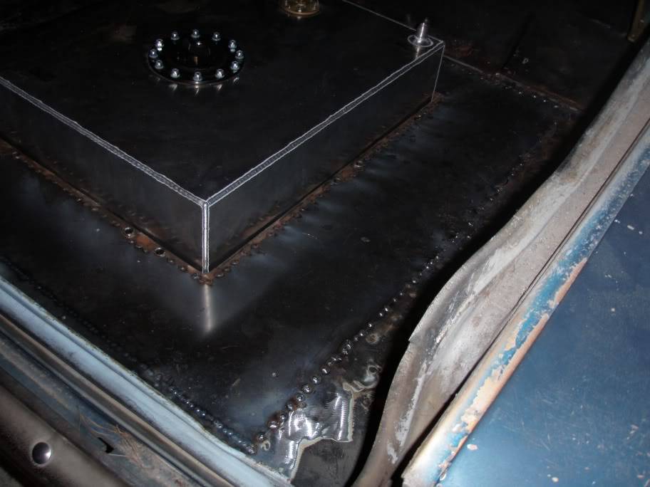
One requirement of this project is that I have to have some provision for a fuel return, which the stock mopar tank obviously didn't have. I purchased an RCI 20 gallon tank and cut out the trunk floor for installation. I didn't want the tank sticking out too far below the car, and at the same time I didn't want the tank to be too high up in the car, so I placed it halfway. In the pics below you can see the frame I built to cradle the tank, and also the filler panel that I welded in this weekend.
The nasty looking strap you can see is a prototype I made from the old tank strap. I'm using the one you can see here as a template for a
cleaner looking set of straps.
 Sean
Sean
06-21-2010 #18
Registered User
- Join Date
- Jan 2009
- Posts
- 197
I'm debating on what pump to use as a low pressure pump to lead into the surge tank.
Anyone have any suggestions?
What do you think about this one? http://www.summitracing.com/parts/CRT-P4070/
I absolutely do not want any rubber barb or plastic fittings in my fuel system. Also I'd like the pump to be as quiet as possible if at all possible.Sean
07-13-2010 #19
Registered User
- Join Date
- Jan 2009
- Posts
- 197
Update:
I finally got the intake welded up! I'm stoked! Here's some pics:
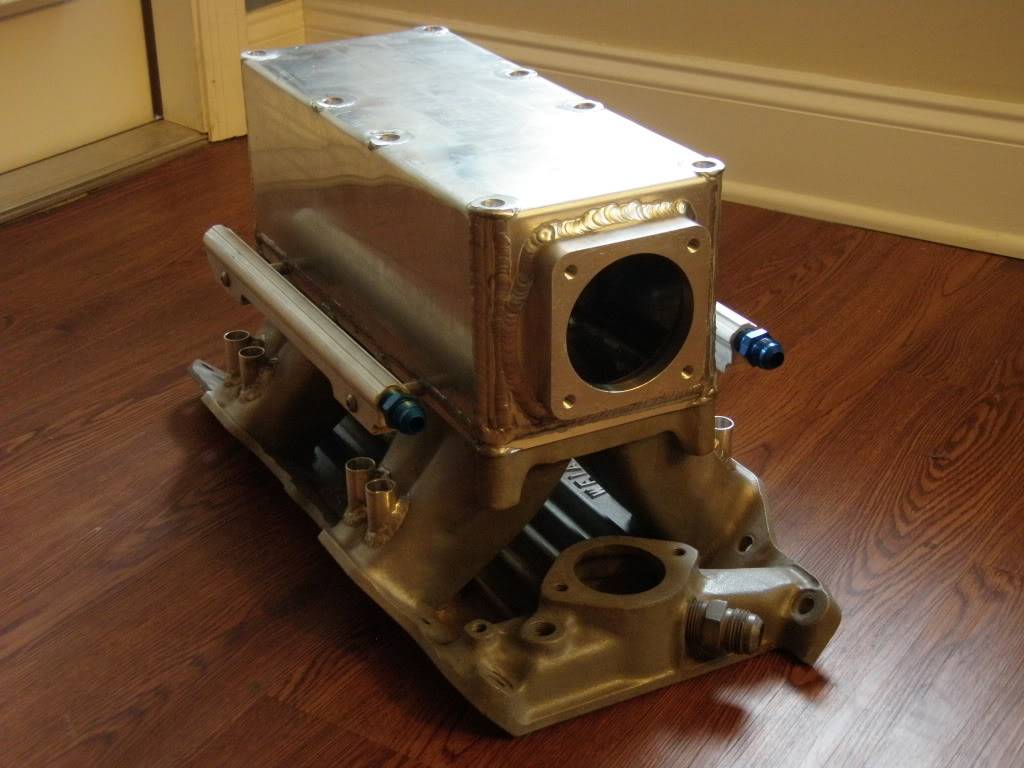
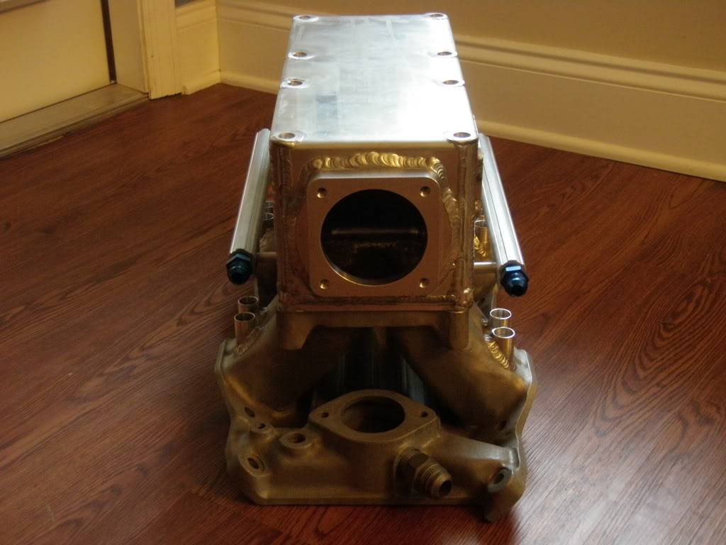

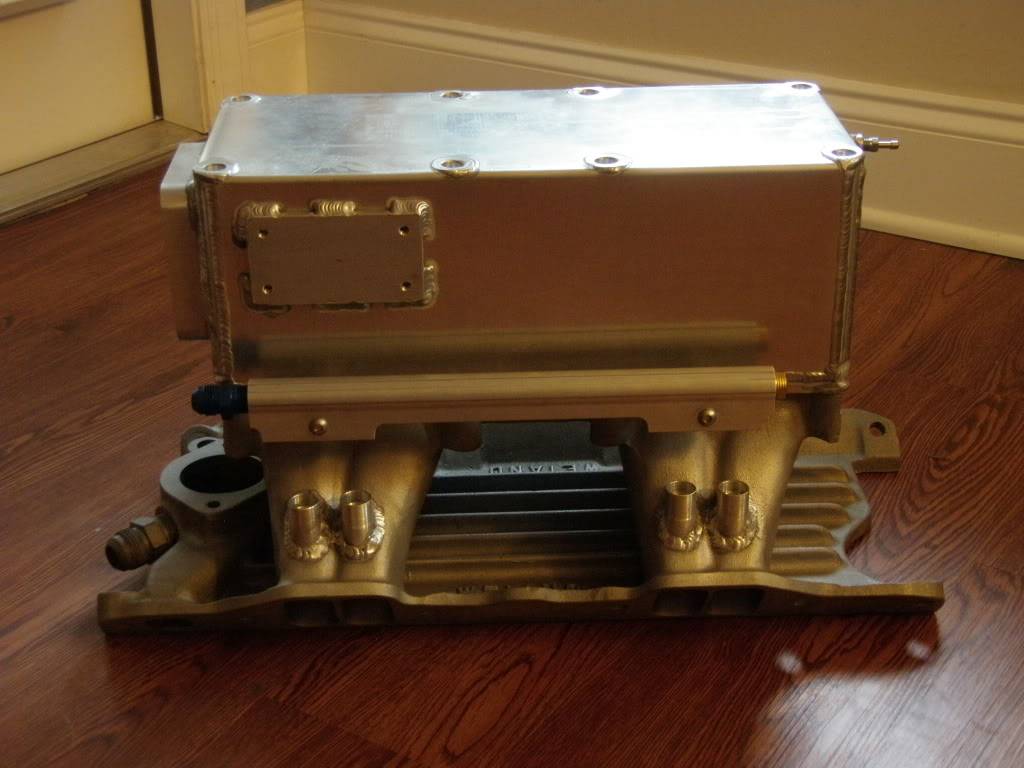
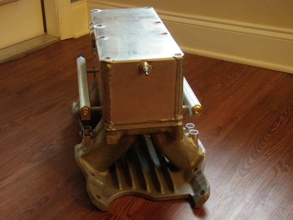
 Sean
Sean
08-17-2010 #20
Registered User
- Join Date
- Jan 2005
- Location
- Central, Ky
- Posts
- 313
[email protected]
more car pics?2003 Crewcab Dually Dirtymax
1980 Malibu...6.0 LSx turbo on the stand.
2000 SS th400 little juice
2002 C5 glide swap, motor shopping
1970 Nova... still waiting.

 Reply With Quote


