Results 1 to 20 of 41
-
05-03-2009 #1

 Registered User
- Join Date
- Nov 2008
- Location
- So. Cal.
- Posts
- 1,240

Air ride, Watts link and Sway bar build (long)
Hey guys. I just got done changing my rear suspension abit and thought you might like to see some pics.
My car is a 62 Chevy II Nova coupe that I bought in 1995. Was just gonna keep the 350/350 combo and have fun driving it. But the front drum brakes were just too scary. So I installed a Mustang II front (build pics on that later) so I could have disc brakes. And with the nice front I wanted a lil more at the rear. So I bought an Art Morrison 4-link rear clip and installed that. Built an edelbrock injected engine then had a few changes in life. Family (wife wanted kids), moved to a house (was in a condo) and my job was demanding more, more, more. So the car, still un-driven was put on the back burner for many years.
I retired last year so full steam ahead on the car. The 4-link was used for simplicity of the build back in 95 when not much was available for the Novas. But after thinking about it I didn't like some of the characteristics of the 4-link. Narrow pan hard bar and the coil over placements. I did alot of looking around and decided to use air ride technologies air ride system with the shockwave air springs and hydraulic shocks. And I couldn't get a longer pan hard bar in there, the one I had was only 24" long, too short, the rear would wallow around on the street, yeah, I did get to drive it around on the local neighborhood streets a lil. So I liked the idea of a watts link. The kits that are out there are great!! But again, I was limited on space so I made up my own. No real cost savings..
So here are some pics of that install. It was fun, and frustrating at the same time..
I have never worked on cars before, this is my first. And I never welded before. So you will see alot of odd looking ideas and some bad welds. I know cause I have to look at them everyday LOL But,,, its the best I can do and its solid so Im not afraid of it coming apart.
Anyway, enough of my back peddling trying to justify the rough looking work. Enjoy and please comment, any of your knowledge will be great for the next project (71 Fiat spider with a large-ish V6. JR
When I bought the car, 1995....
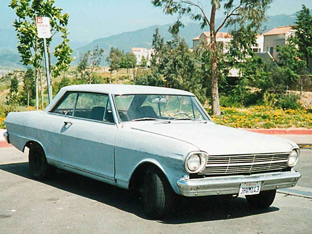
Art Morrison rear clip.
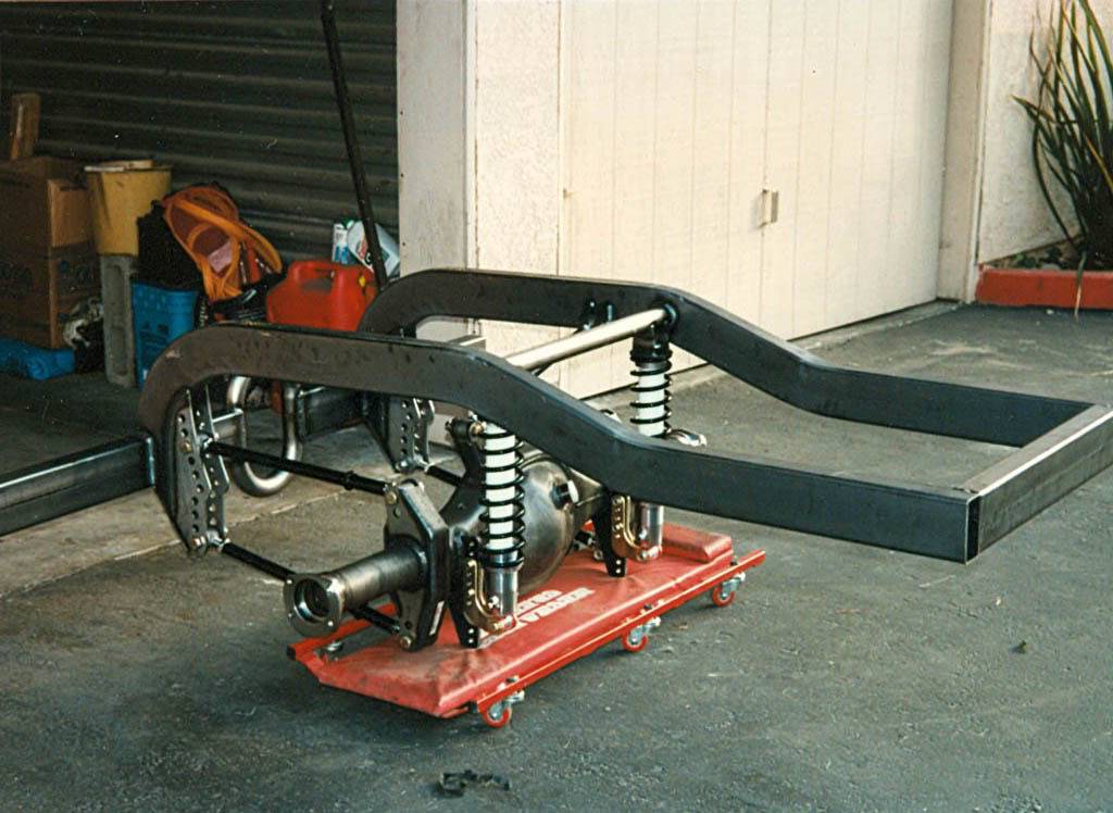
After the rear clip install in 95. Thats kinda covered in another post of mine. Wont bore ya more than Im gonna
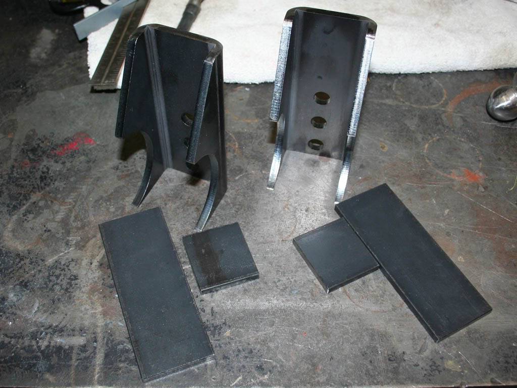
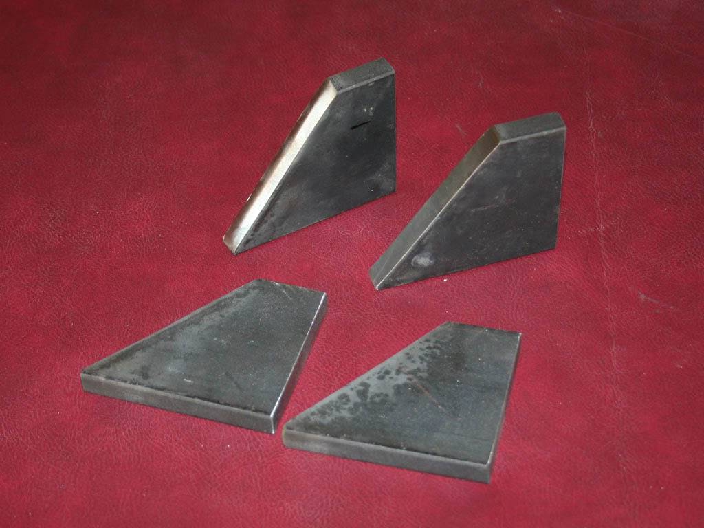
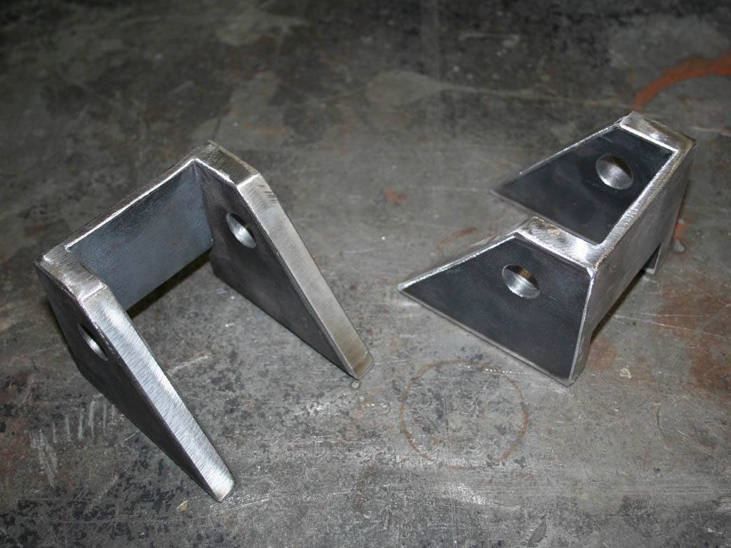
First job at hand was the lower shockwave mounts. I used some 9" leaf spring perches cut in half. Had to use two cause they aren't exactly in half. They are heavy duty brackets, 1/4" bent steel. Some additional 1/4" plate to add to the beef of it. I was going to be using the holes in single shear for the shock mounts and I thought a 1/2" would be better than a 1/4" shear plane.

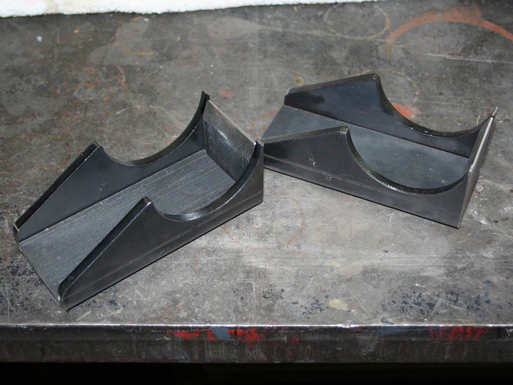
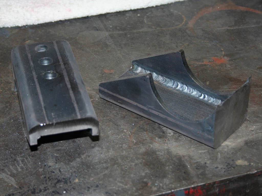
TIG welded up and ready to go.
MIG welded onto the axle housing. I didn't disassemble the housing. I did make sure all the weight was off the housing for the weld. And I welded in about 1.5" sections and cooled the area with a damp rag in between. Took a long time but it never got the housing tube past warm to the touch after cooling. And I beveled the heck out of the brackets so the penetration is pretty good. They aren't going anywhere.
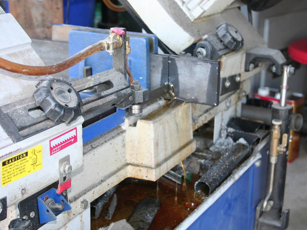
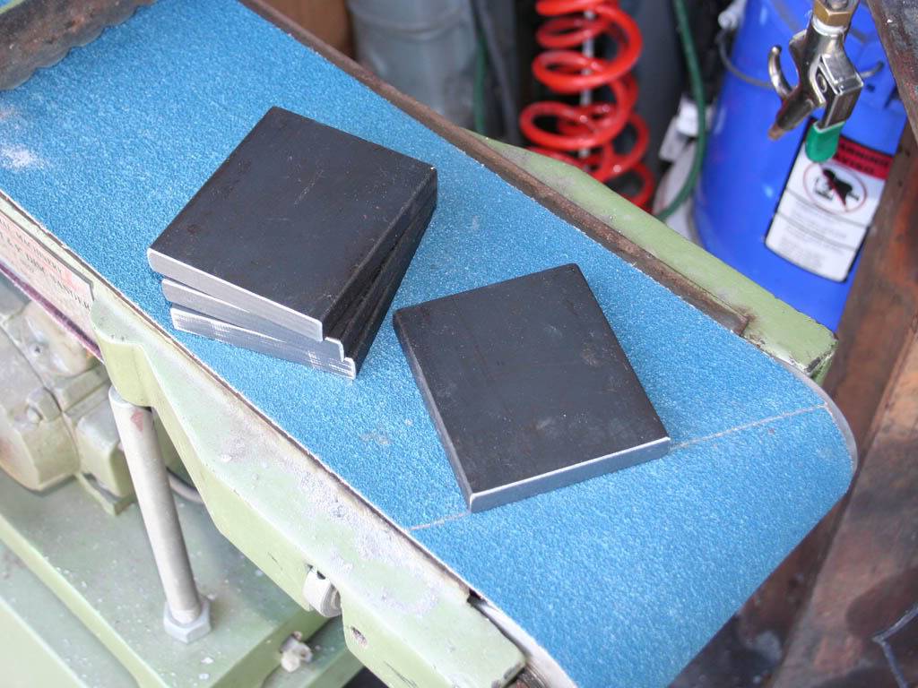
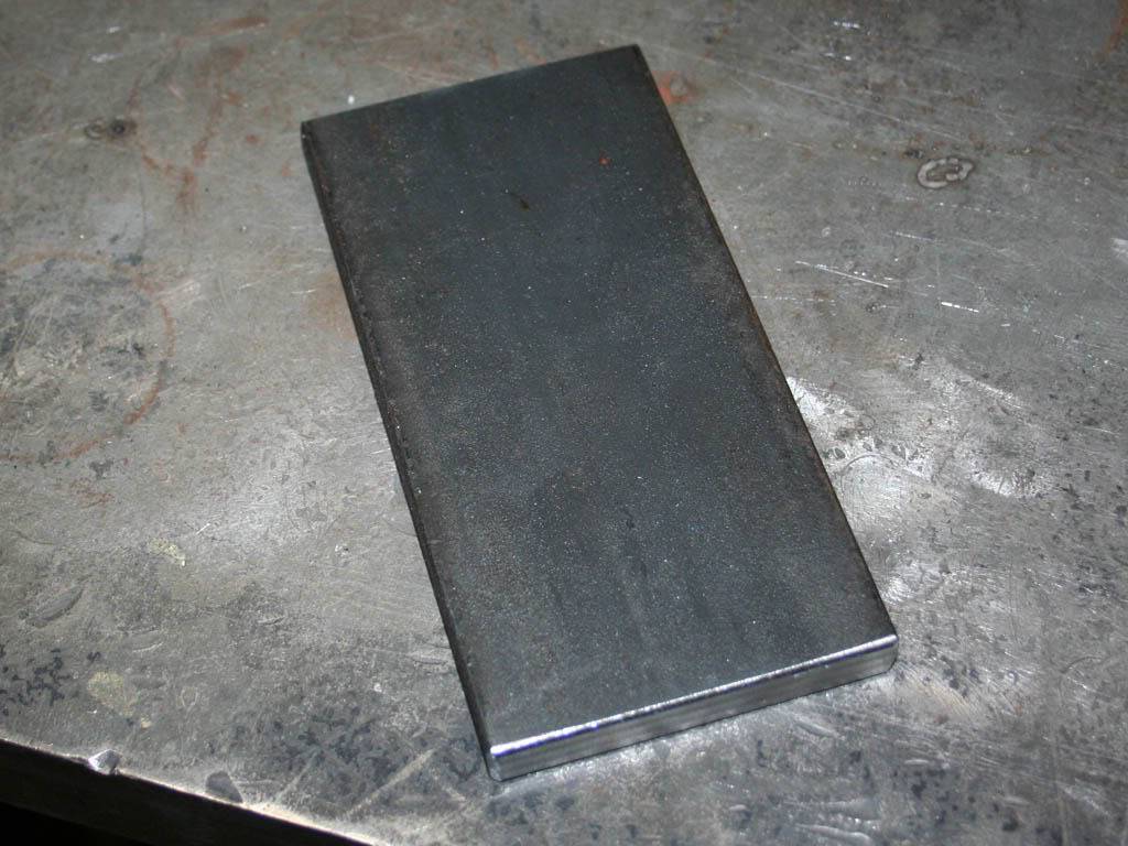
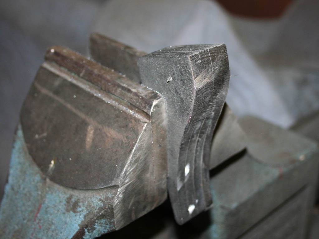
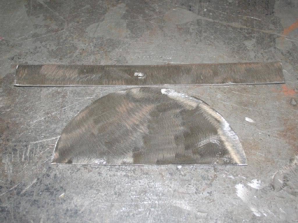
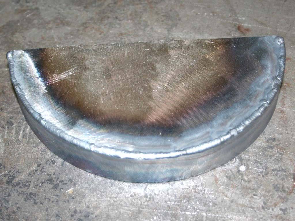
Next was the upper mount. I get alot of use outta this lil 7" band saw.. 1/2" plate.
-
05-03-2009 #2
Registered User
- Join Date
- Nov 2008
- Location
- So. Cal.
- Posts
- 1,240
Plasma cut the extra off to make the right shape.
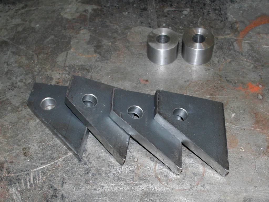
Shock used for placement of the upper mount. It is all at ride height. Coilovers still in place. I made some stainless steel spacers so if I need to adjust the 4-link in the future I have some wiggle room inside of the upper mount. The 4-link bars are at their shortest length right now. If I adjust them it may move the rear end back some.
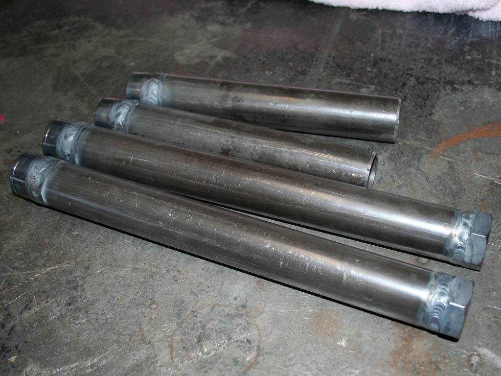
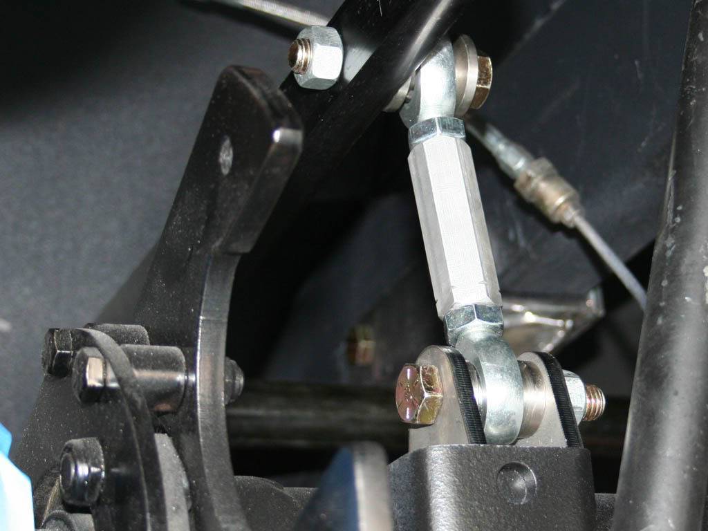
Time to weld in the uppers but no way did I want the shocks in there, rubber!! So I made these links that are the same length eye to eye as the shocks at ride height. And they were gonna be needed for the watts link welding too. They helped to get each side of the car exactly right for height when making the watts. I measured everything so many times, jumping back and forth. But the sides are equal to within a 32nd of and inch. And thats axle to frame and body to ground.
Plasti-coat bed liner paint I love so much, you will see it on everything.
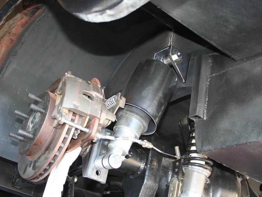
Finally, the coilovers are outta there, full weight on the struts I made. Ill need the additional space, going be filled up soon.
05-03-2009 #3
Registered User
- Join Date
- Nov 2008
- Location
- So. Cal.
- Posts
- 1,240
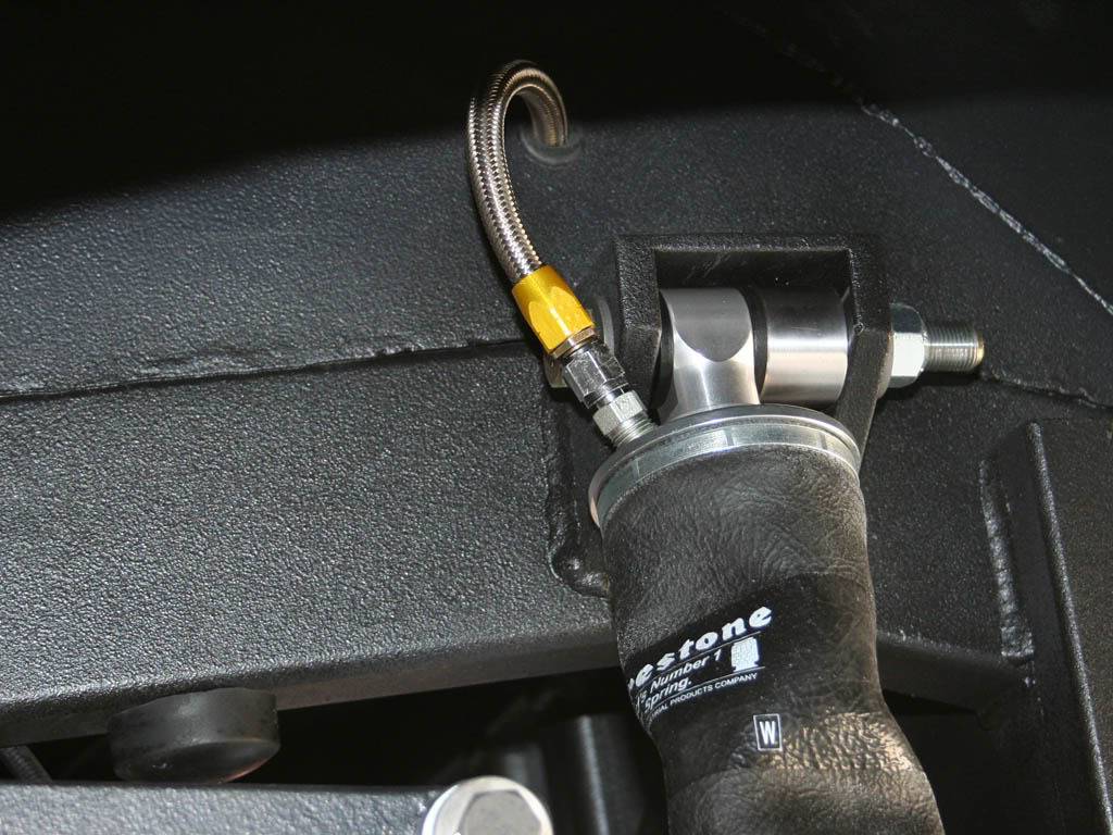
I was a lil pissed. AR sent me the shockwaves with the optional air can (big ugly can over the bag) they sell for a hundred bucks. I didn't want it, looked cheesy IMO.. But. I thought I would give them a chance. If I didn't like the look I could remove them later. No, they didn't charge me for them. Guess they were having alot of problems with guys tearing the bags due to close tolerances. So I really didn't want a massive aluminum can sitting in there. Time for some plasti-coat!!
Ghetto paint booth LOL
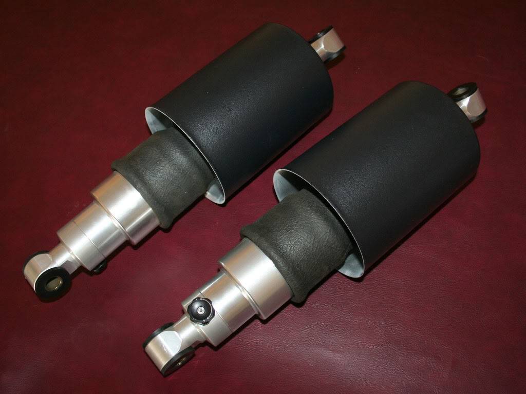
So thats the coilover swap. Watts link next..
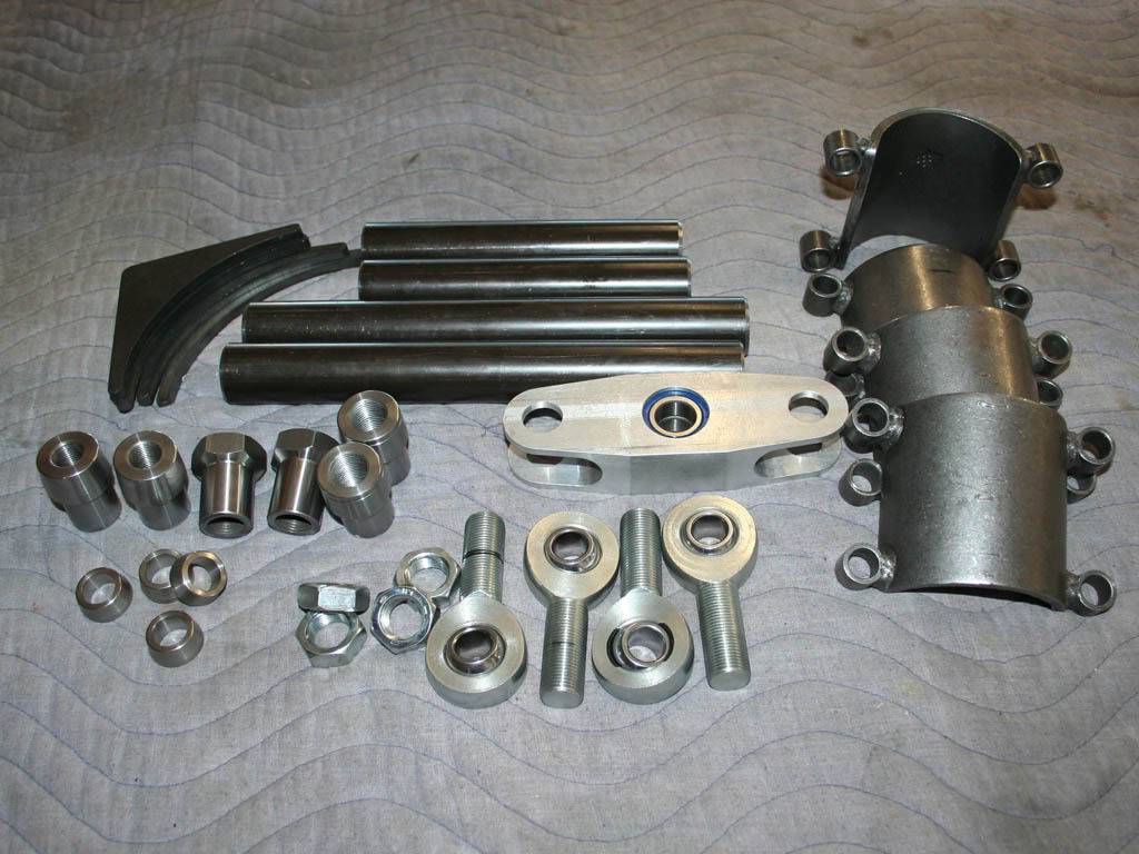
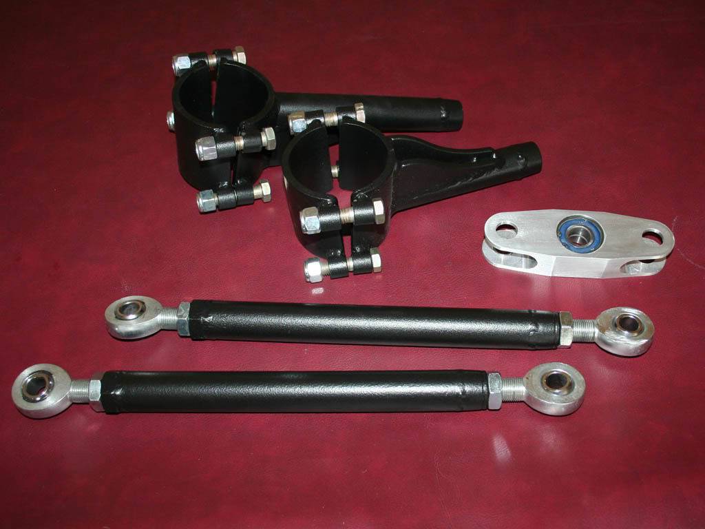
Watts link time.. I stole some ideas from just about everyone. Looked at ALL the pics out there. Came down to space limitations. I ended up just going simple.
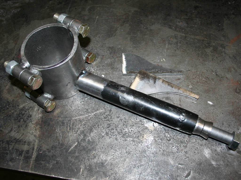
I bought the center pivot from Tim over at Fay's 2. Nice piece. And the DOM tube and weld in ends from another company. I used QA1 rod ends, some of the best out there. I used 3/4x5/8" instead of the 3/4x3/4" Tim uses so I had to make some shims for the center pivot arm mounts.
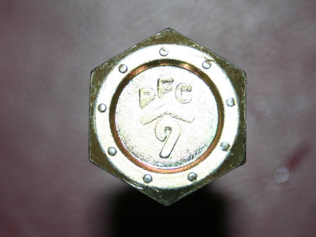
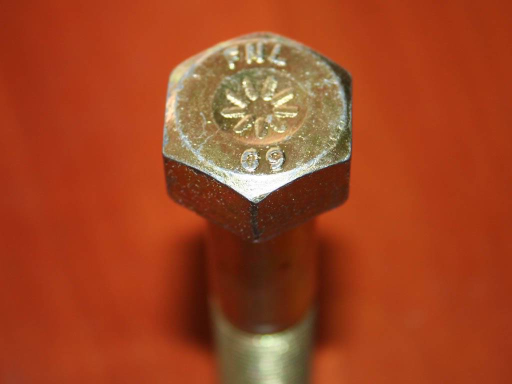
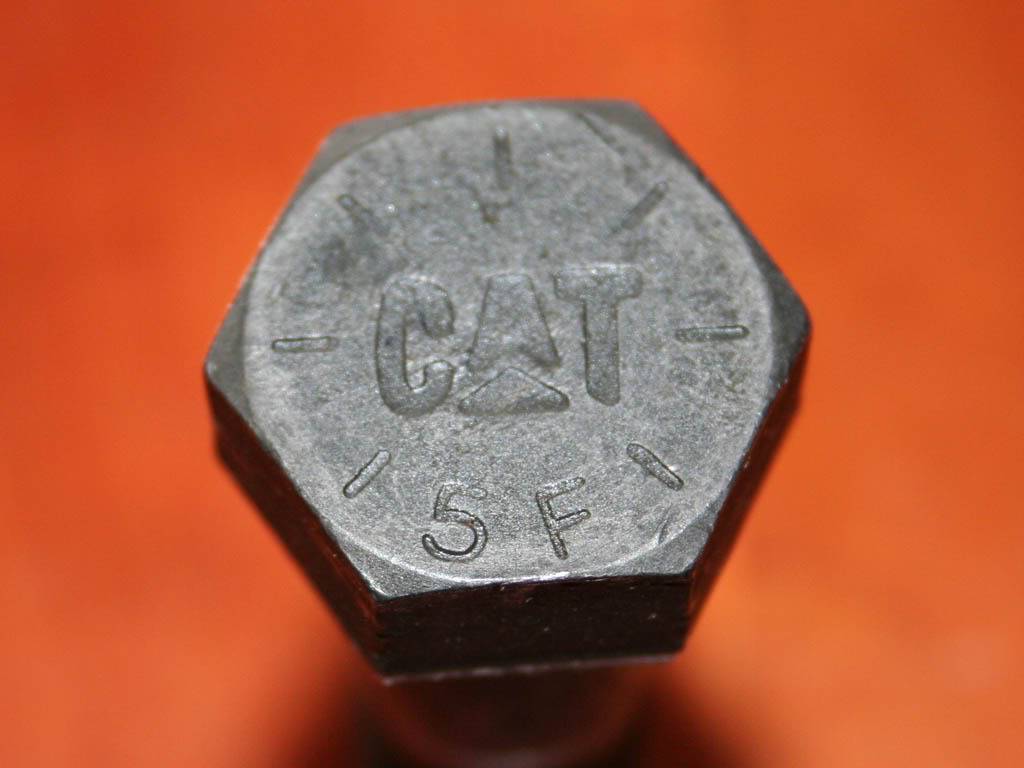
Now bolts. I could go on and on about bolts. But basically I looked into some NAS (aircraft) bolts cause this stuff is in shear, watts and shock mounts and I wanted the proper grip length. UMMM!! 90 bucks a bolt. I called seven companies all over the US. Yeah, all the regulars, AC spruce, coast fabrication, and all the same. So there are "grade 9" bolts available. Fastenel, Grainger (PFC) and CAT were who I used to get the right length bolts so ALL the shear joints had the grip in shear, never the threads. The grade 9 bolts are all 180k PSI. And really, they are great fasteners and the price was right. Still a couple hundred in bolts.
Anyway.. Some pics....
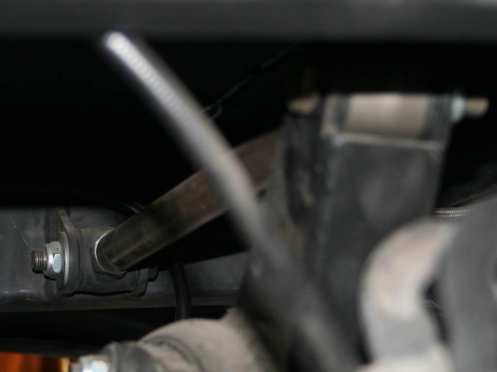
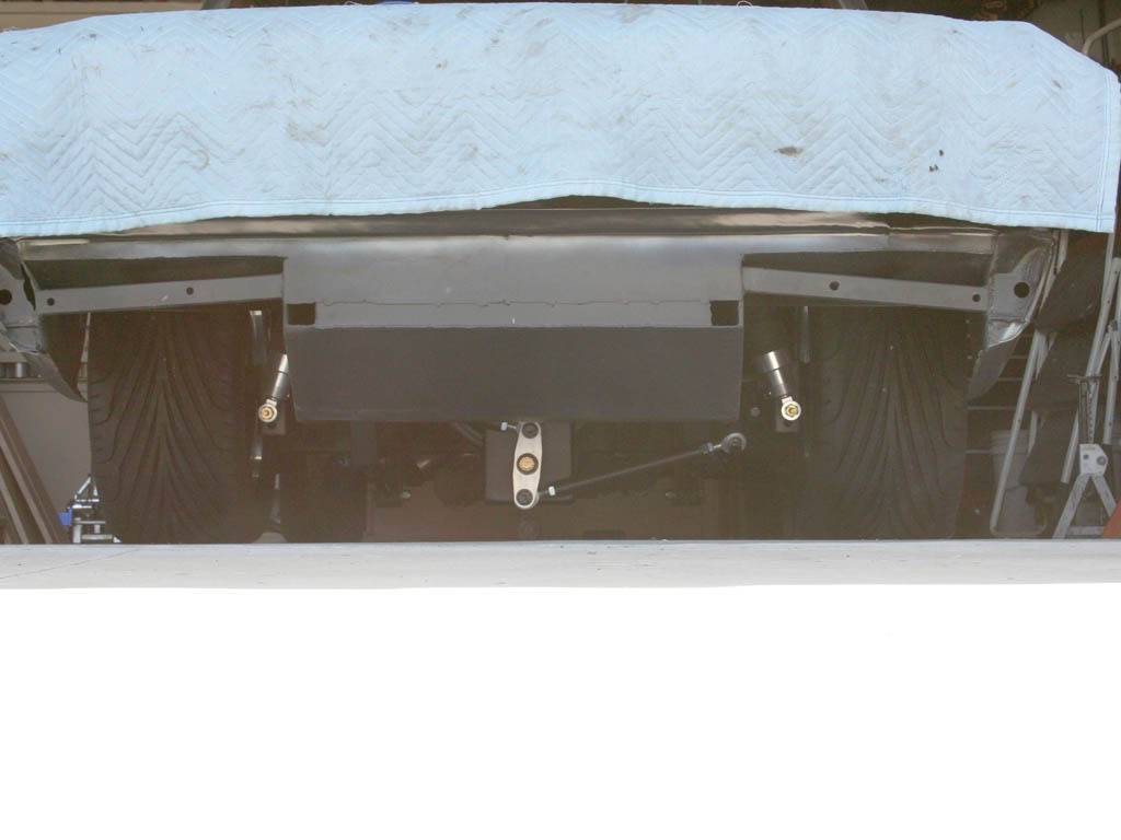
This is the original pan hard bar, very short, gotta go.
My shopping list. Prolly four dealers here
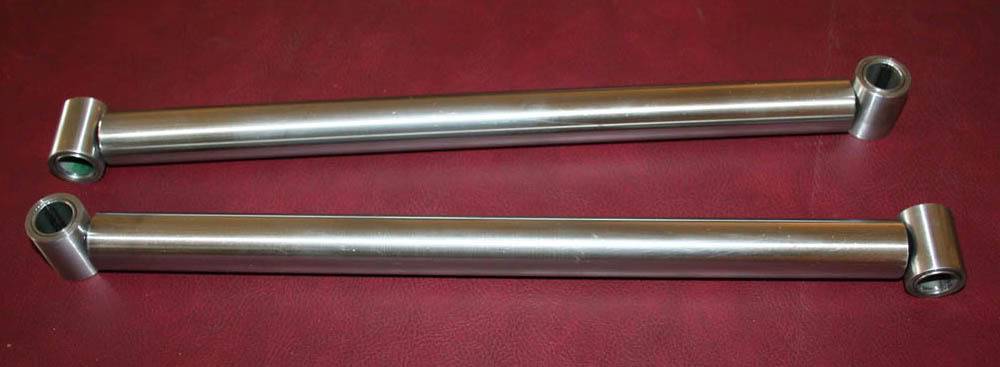
Links TIG welded up. I know, not the greatest welds but they are HOT and deep. Had to chase the threads after welding.
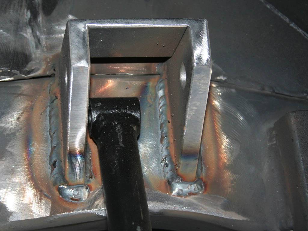
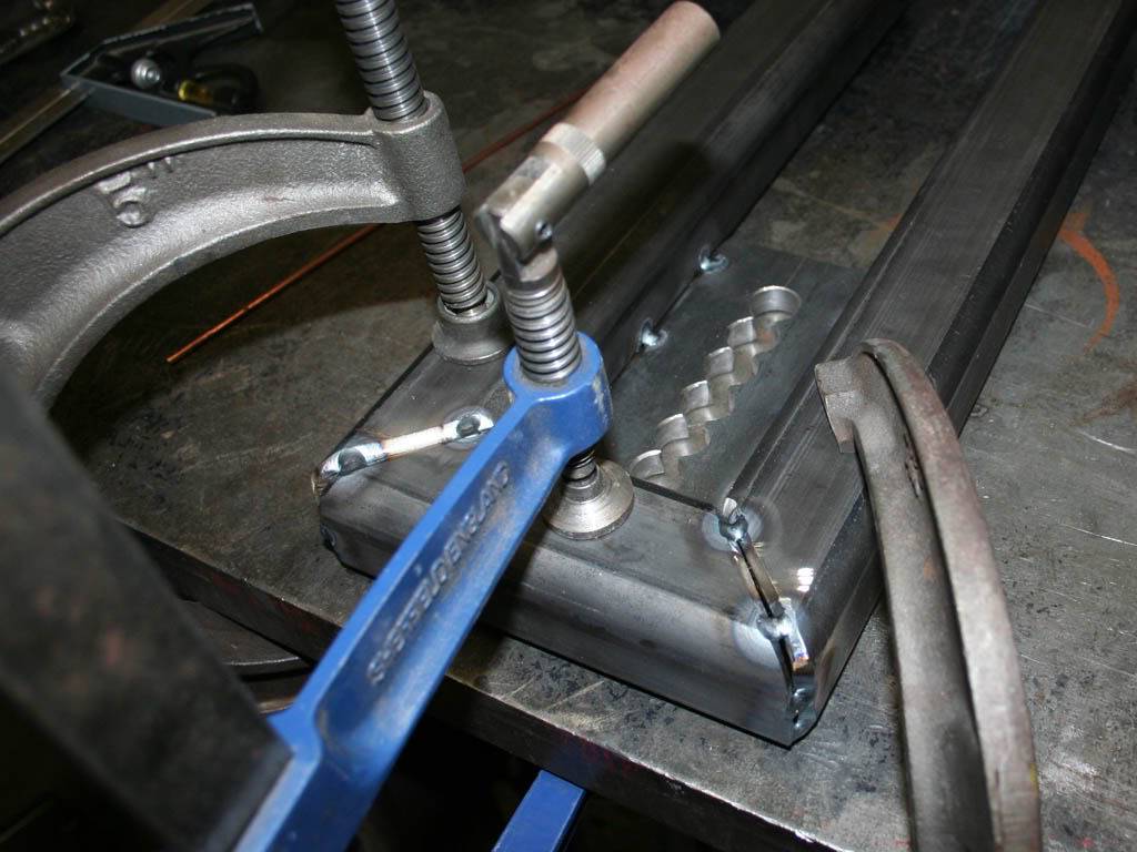
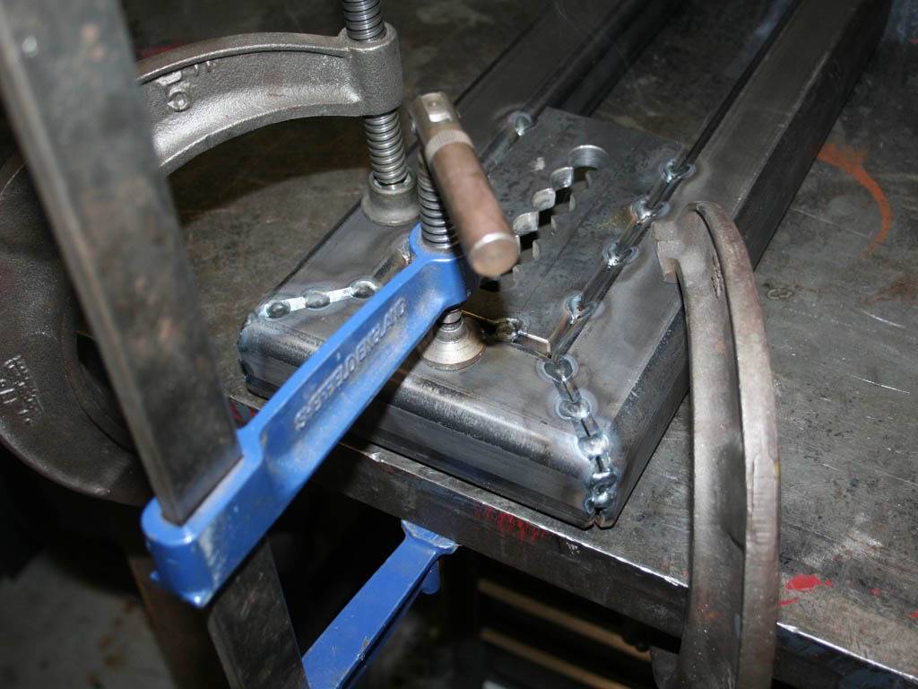
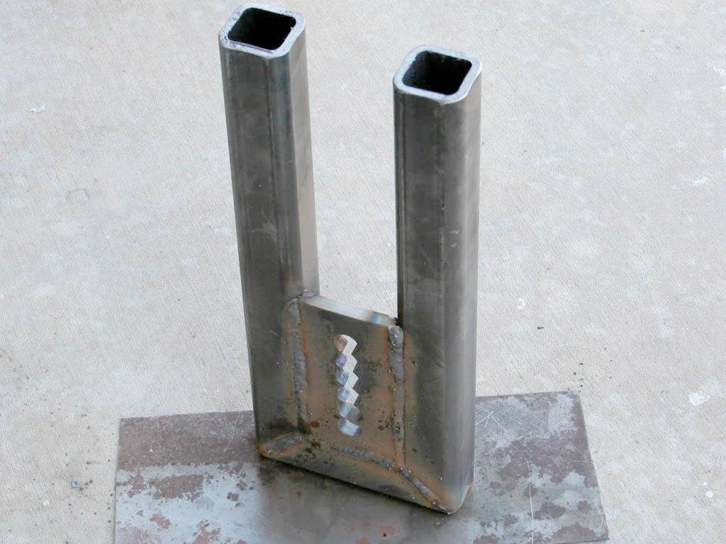
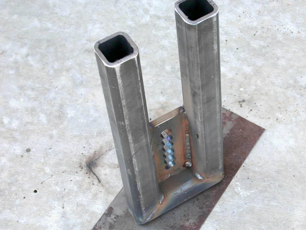
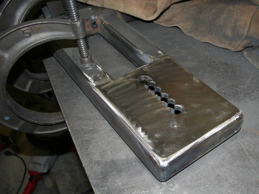
And the center pivot mounting. Started as a 1/2" plate. I drilled the 3/4" holes under sized and reamed to a tight slip fit for the center bolt. Then clamped it up to my welding table, its a beast of a table. I used some 2x2" 1/4" wall tube. The stuff is very stiff. Tacked it up, both sides, heavy beveling at the joints then took it outside to put some real heat to it. MIG welded it up tight. Sanded the welds down on one side to have clearance for the center pivot and it helped the appearance too.
05-03-2009 #4
Registered User
- Join Date
- Nov 2008
- Location
- So. Cal.
- Posts
- 1,240
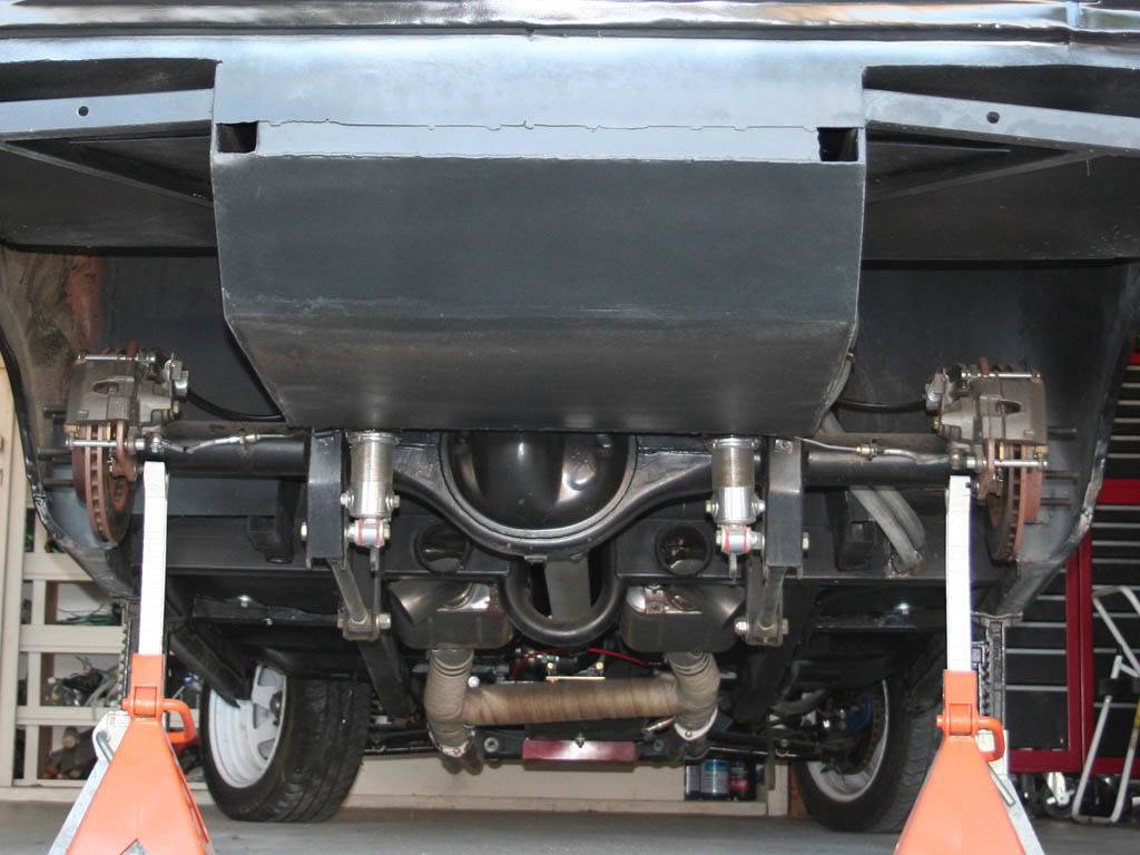
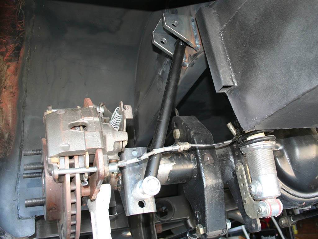
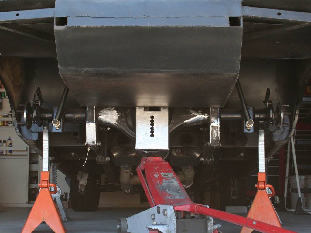
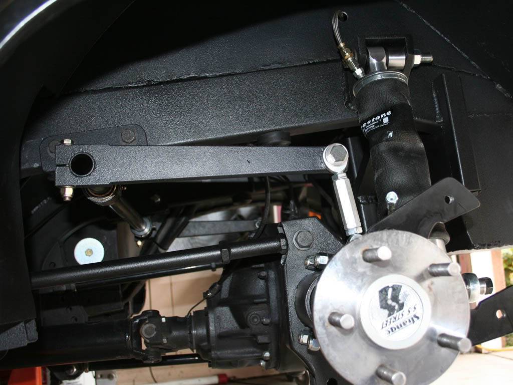
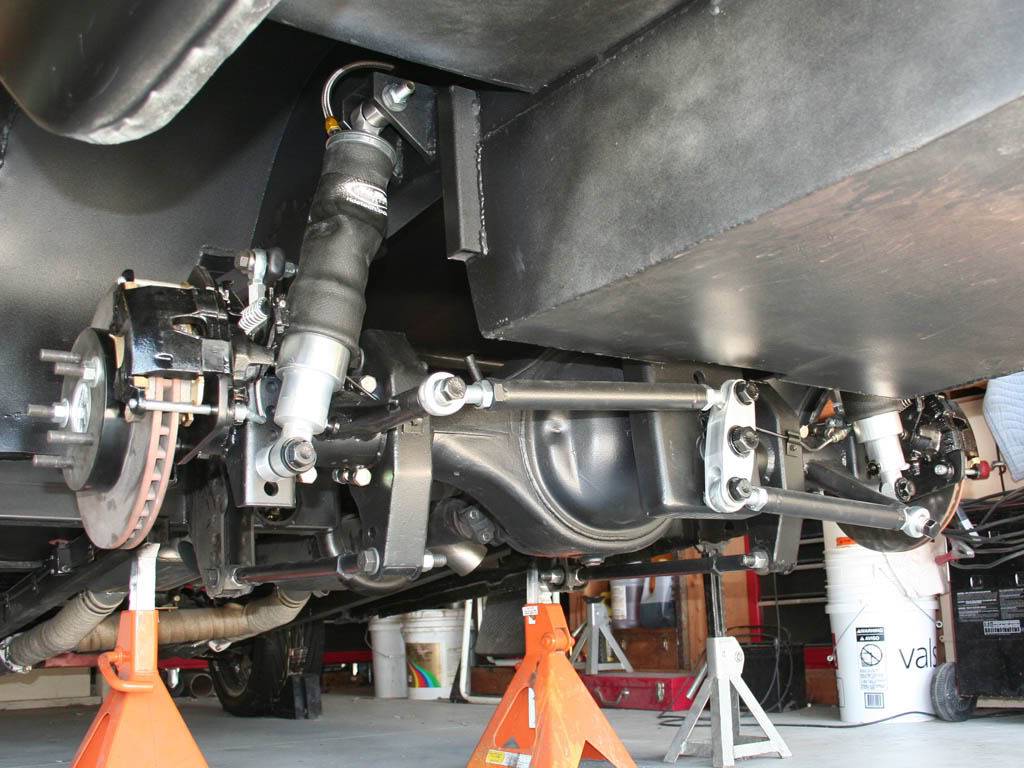
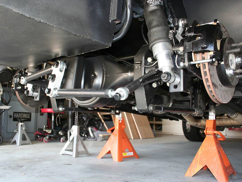
Test fitting it up in the car. I used the same 2x2" tube for the cross member to attach it to the frame. I made some angled braces out of heavy walled 2x1.5" tube that would be up above the line of site. Welded it in. That my friend was a drag. Up under the car, leather draped everywhere on the car and myself as Im on my and had to be directly under the weld to see it. And I had the welder on full tilt, welding the 1/4" wall tube to the frame. Heavy bevels again. But I wanted a SOLID connection. Nothing worse than cold joints, not a one here. But it was tight, just to get the gun tip in there, and I dont pull the trigger unless I can see the joint (auto helmet is a must). Wasn't diggin this part at all.
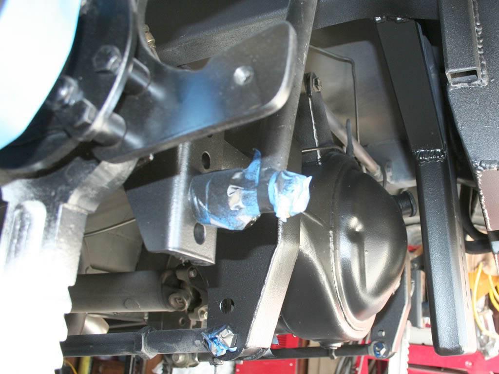
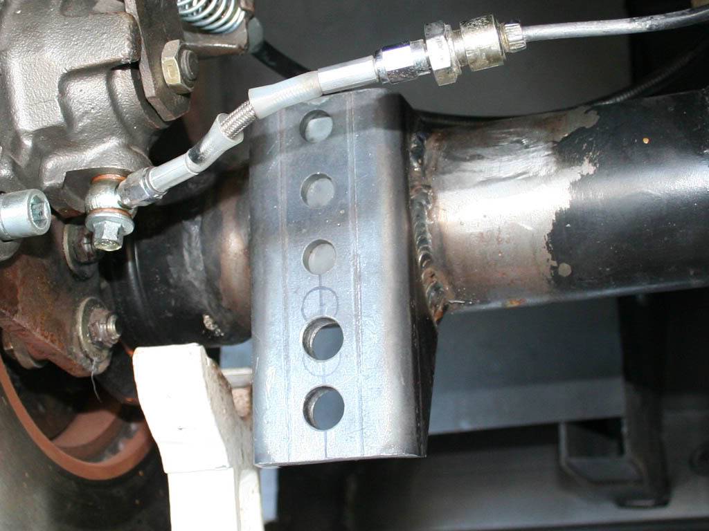
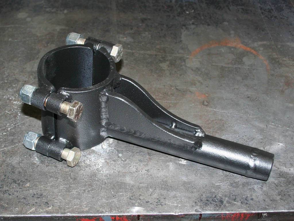
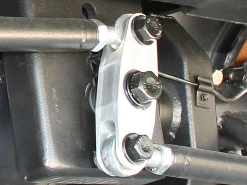
Next was the axle tube mounts. Stole this idea from Tim at Fay's. Sorry. Heavy duty 1/4" steel axle clamps. Oh, they dont move at all with just the slightest bolt tightening. Clamp them down tight and they are NOT gonna slip. The full contact makes them so solid. I was kinda wondering if they would deform my axle tubes if I really put the wrench to the bolts so I clamped them up to a thin walled exhaust tube I had. And really laid on the wrench. Didn't deform the 16ga tube at all, no worries for the axle tubes. Oh, and there was alot of pre-weld measuring steps, alot. The arms are clocked different for each side.
Welded while clamped.
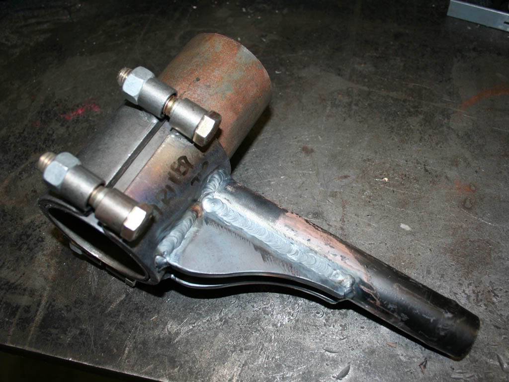
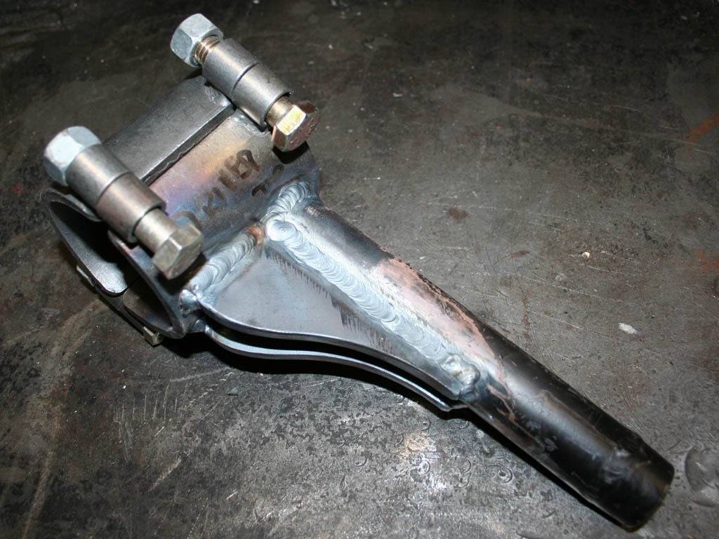
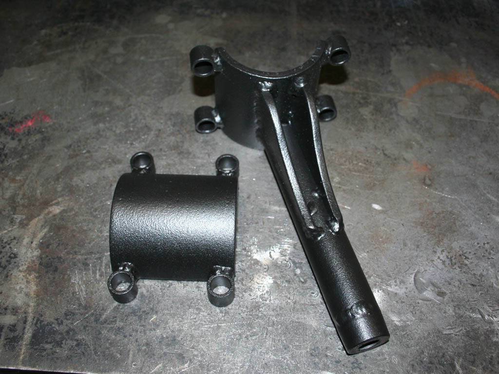
Ready to bolt up
05-03-2009 #5
Registered User
- Join Date
- Nov 2008
- Location
- So. Cal.
- Posts
- 1,240
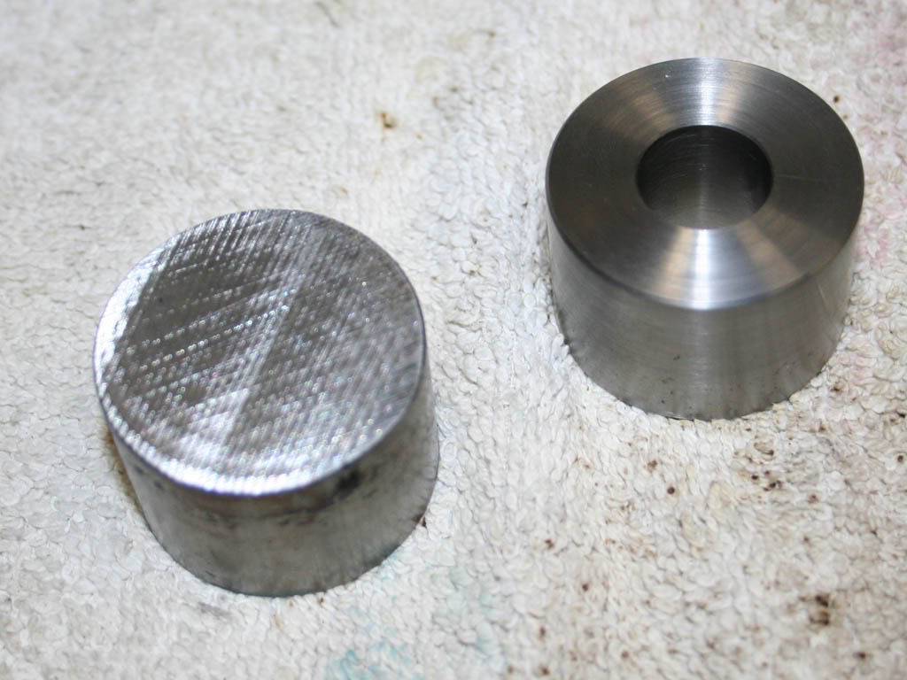
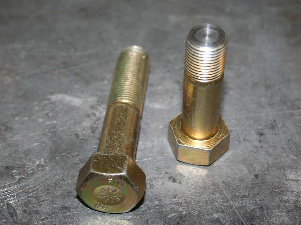
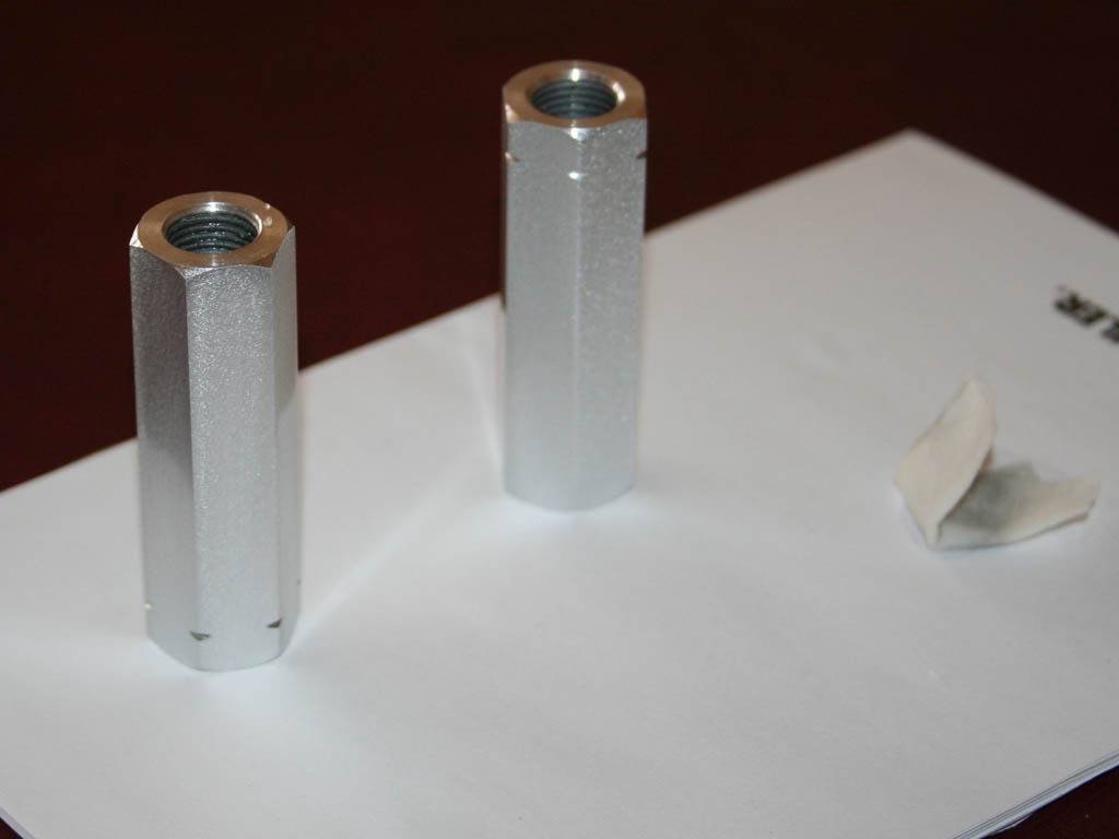
Oh, and bolts.. Some of the fasteners if yer interested. These are all "grade 9" bolts. But I wanted to show how they are hardened. Pretty cool actually. I had to turn down the watts link arm pivot bolts to get the right grip length. I really noticed how hard the outer case hardening was on the bolt and how it got softer at the center. You can see it on the turned end. And when I say hard I mean it. I was using some good carbide inserts and for a second I thought about grabbing the CBN inserts. But I just cranked up the RPMs and let the sparks fly, I love hard turning But you can see the softer center of the bolt. Thats a good bolt. Not just a bulk hardening of the entire bolt. Has a hard outer surface, pretty deep really, and a softer core. Dont ever let anyone tell you a grade five bolt is better cause a grade 8 bolt is too hard, its just comical some of the threads I read.
Ok, so I'm gonna wrap this up. Sway bar is next. I looked into the sets available. Again, space was an issue, and rates really. My lower roll center with the watts link is gonna give more body roll. So I asked and looked around alot for a good starting point for the bar spring rate needed. Kinda a shot in the dark really without driving the car. But I decided on around 295lbs for the bar. And I already decided on a three piece bar from Speedway Engineering. They have some great stuff, many three piece bars you see labeled under a diff name may be their bar.
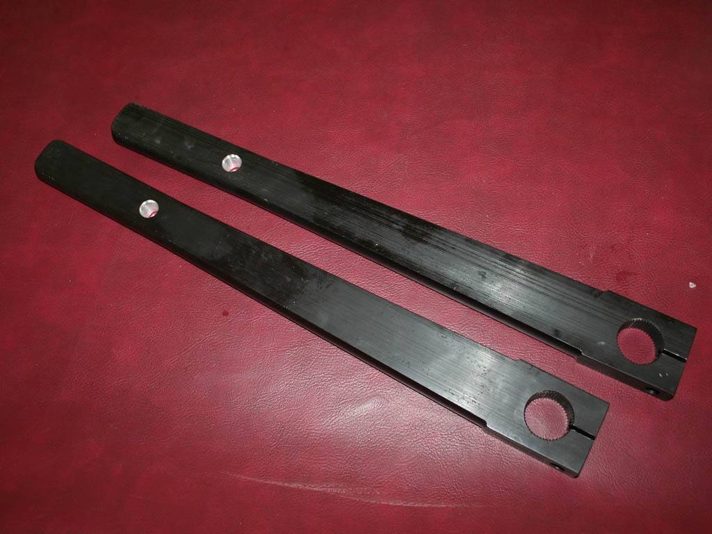
Its a straight torsion bar, solid or hollow, with splined ends. The arms are splined also and they come undrilled for the links. So you determine the rate you need and find the length bar that will suit the space issues. Thats where I screwed up, had to buy another bar cause my tires were too close to the first bar's arms. So anyway, get yer rates you need, the length bar that fits and drill the arms for the proper rate. They can be drilled from 10 to 15 inches for various rates.
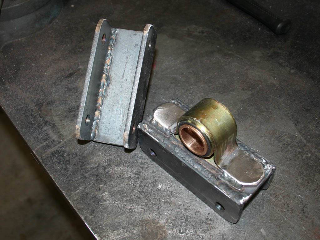
I ordered the low profile pillow blocks. They come drilled to bolt them to the frame. I wanted a different mount. I made some brackets to bolt through the frame sideways instead of up through the frame.
I had intentions of being able to slide the mounts fore and aft to adjust for sway bar rates and just change the arm mounting holes. Not gonna happen that way. Too difficult to drill perfect holes through the frame. So I'll just get a different bar, same length but different rate if I need to change the rate later down the road. Gotta drive it first to even get to that point. So, here are the pics...
Made some brackets for the pillow blocks. It was a slow process. There is rubber in there. So I plug welded the holes up, cooled with a wet rag in between, made a weld, cooled, and so on. Never got it hot on the rubber side. LONG process.
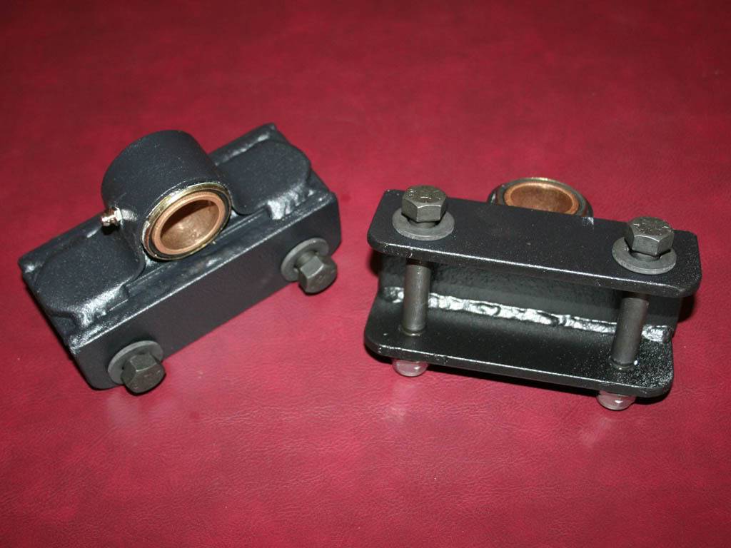
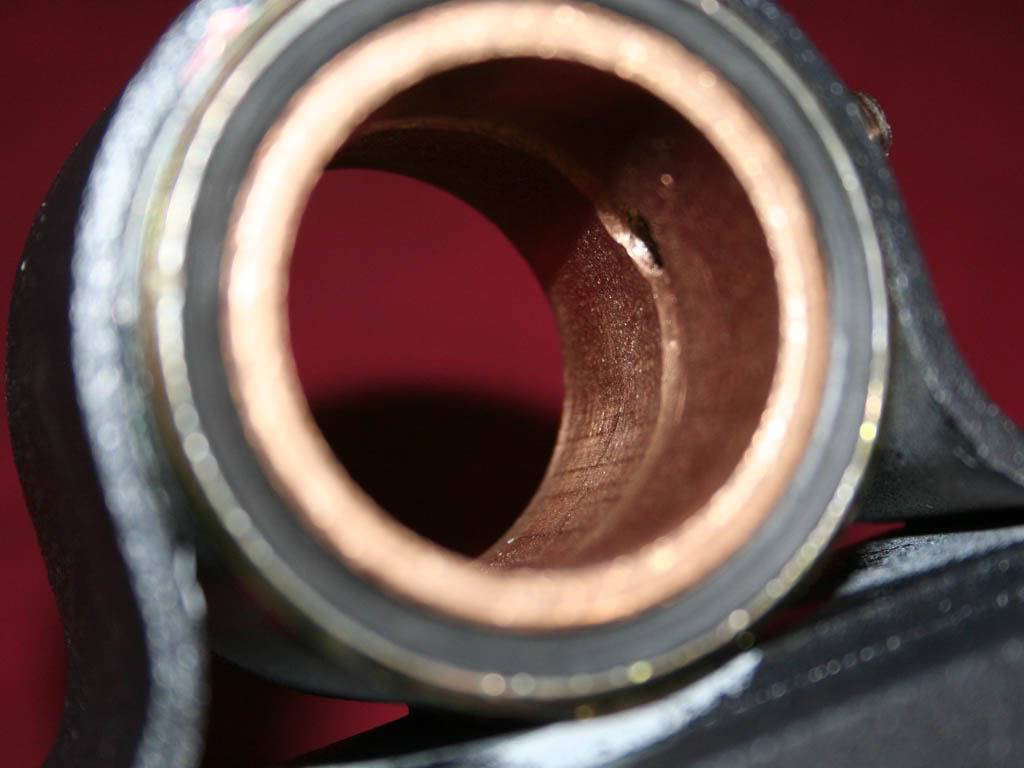
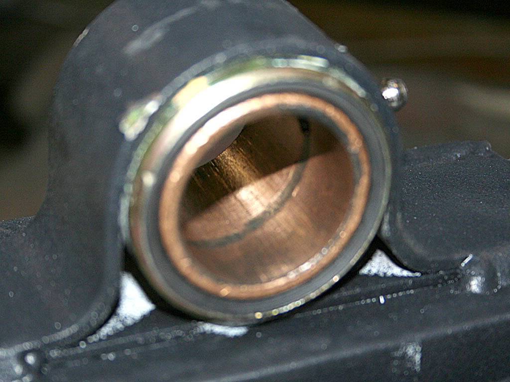
They weren't set up with zerks so I drilled and tapped some holes and put on some zerks. I also lightly grooved the bearings in an outward spiral direction to allow the grease to move to the entire surface of the bearing. It seems to work, I have done it on some bed mills too.
Made a lil tool to help with holding the bar and pillow bocks up while I figured out the placement.
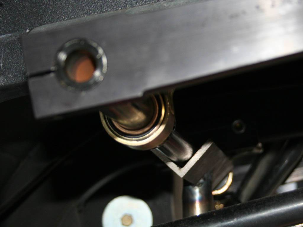
Arms drilled and reamed for the links.
Measuring up the link mounts. I can conveniently use the flat I welded to the spring perch earlier. Yeah, it was planned. Yeah RIGHT!!!
05-03-2009 #6
Registered User
- Join Date
- Nov 2008
- Location
- So. Cal.
- Posts
- 1,240
Some Zoop seal to protect the links?? I'm just looking for stuff to Zoop, have so much left over from the wheels I did..
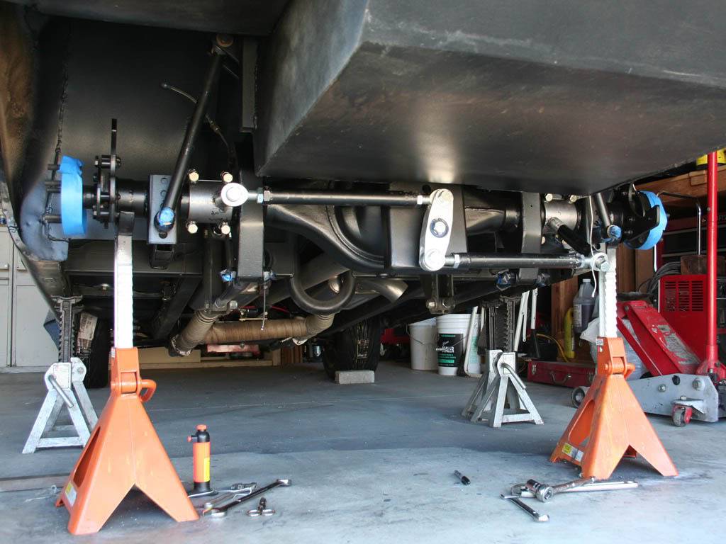
Ok, I know, long thread. Here are the last pics as its all done..
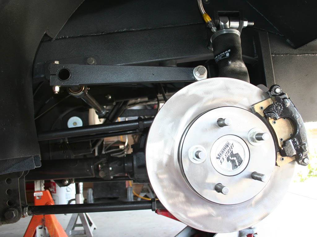
Comparison
Before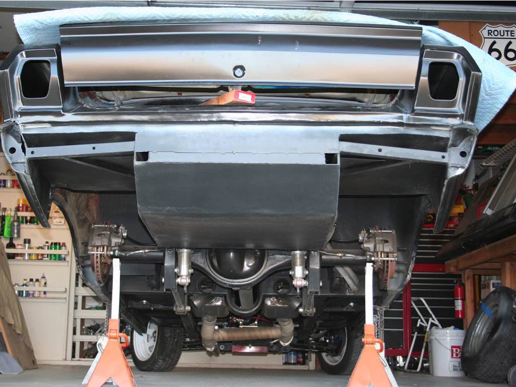
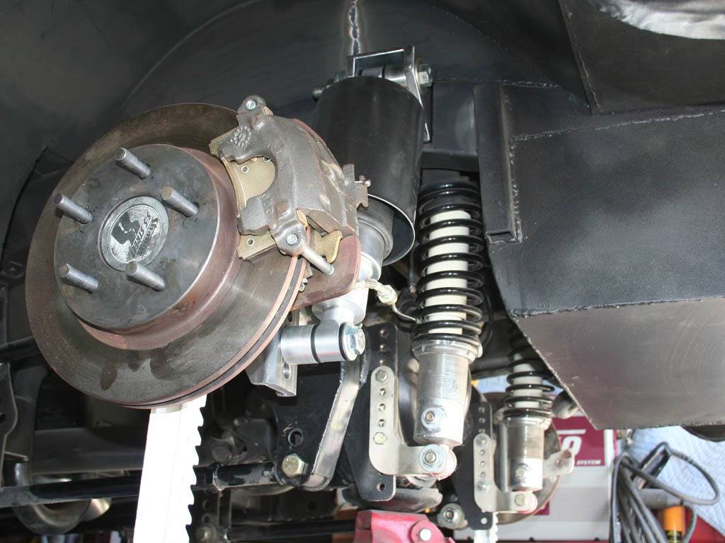
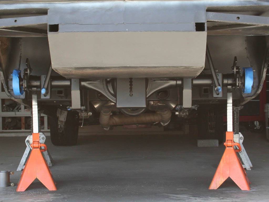
After
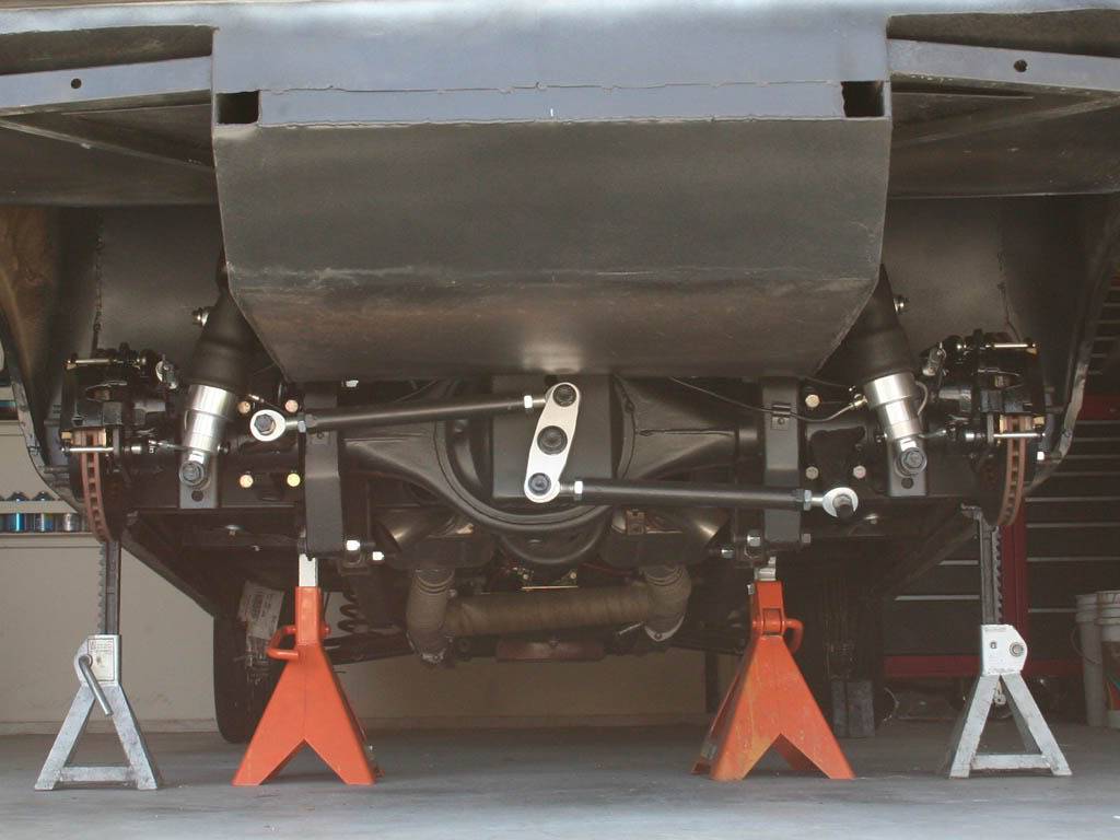
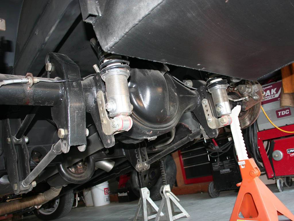
On the ground, not ride height but sitting on the bump stops.
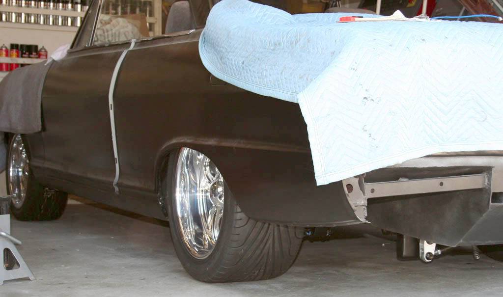
Sorry for the long thread, I still had to edit out a hundred pics. And I tend to get a lil long winded LOL The front end is jacked three feet in the air and the control arms are on the bench getting welded on this week. Hope the front goes faster. Thanks for reading, JR
05-03-2009 #7 - Sponsor & Rat Pack Member -
- Join Date
- Oct 2004
- Location
- Indiana
- Posts
- 1,371
Oh. My. God. There will be NO question of anything bending, deflecting, or twisting...ever!
Seriously...nice work! And nice pictures as well. I love the textured coating on the AirCans and the rest of the suspension pieces.
Its hard to critique the geometry and design fully from pictures but I can't imagine that you have put any less effort into that area than you did the execution. The one thing that I cannot see is where the watts link would attach to the frame. From the pictures it looks like both ends attach to the axle tubes...
Congratulations...looking forward to seeing the rest of the project as it progresses!Bret Voelkel
Director of Innovation Fox Powered Vehicles Group
Founder/ Former Owner
RideTech/Air Ride Technologies, Inc.
How do you spell Impossible?
05-03-2009 #8
- Sponsor & Rat Pack Member -
- Join Date
- Oct 2004
- Location
- Indiana
- Posts
- 1,371
Never mind...I'm stupid...center pivot is attached to the frame...like a rock. I'm gonna have another drink. Originally Posted by bret
 Bret Voelkel
Director of Innovation Fox Powered Vehicles Group
Founder/ Former Owner
RideTech/Air Ride Technologies, Inc.
How do you spell Impossible?
05-03-2009 #9 Registered User
- Join Date
- Dec 2004
- Location
- Midwest
- Posts
- 2,261
Very nice work, I'm sure this one will be referenced over and over by many. Thanks for taking all the time to post!
Kevin Oeste
V8 Speed and Resto Shop
V8TV
Muscle Car Of The Week
V8 Radio Podcast
All about us:
https://www.v8speedshop.com

05-03-2009 #10
Registered User
- Join Date
- Nov 2008
- Location
- So. Cal.
- Posts
- 1,240
Yup, she floats like a butterfly Originally Posted by bret
That was my intension, give the look of what?? Where is the beef. Whats holding it together. That paint makes it difficult to discern the pieces from each other in the pics.
Thanks for the boost Bret. I needed that And really, its just a bolt in of your products. You guys have some of the best phone support I have used, and I have had to use support alot. JR
05-03-2009 #11
Registered User
- Join Date
- Nov 2008
- Location
- So. Cal.
- Posts
- 1,240
Thanks Kevin.. Its ok work, not even like some of the cars on this site. Man!!! Im lost with all the great cars on here. But, they do motivate me. And so do the positive comments. Thanks. JR Originally Posted by oestek
05-03-2009 #12 Registered User
- Join Date
- Jul 2008
- Location
- Dallas, TX
- Posts
- 260
VERY nice!!! I knew you were working on a watts link setup and turned out great. I really dig your sway bar too; very clean.
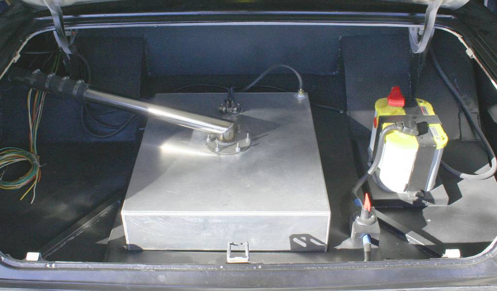
You didn't show anything about having to notch the tank. I'm sure that required some work ;)'69 Chevelle - LQ4/T56
'71 GMC SWB Fleetside - LM7/AR5
05-03-2009 #13 Registered User
- Join Date
- Mar 2009
- Location
- overseas
- Posts
- 3,434
wow - nice work man!
 Kevin S. (overseas in Germany)
1963 Chevrolet Impala 2d ht Coupe
www.CruznArt.com
CRUZN - Automotive Artworks
05-03-2009 #14 -Moderator-
- Join Date
- Mar 2002
- Location
- Redwood City, CA
- Posts
- 1,895,413,640
Wow.... Very nice work. I'll be stealing a couple of your ideas, just so you know. Thanks a bunch. I hope you don't mind.
Allen Ortega
Meanstreets Performance Fabrication
---------------------------------------
Vegetarians are the reason for global warming
05-03-2009 #15 Registered User
- Join Date
- Aug 2004
- Location
- Crown Point, Indiana
- Posts
- 1,107
Great work I can almost say I know exactly what you are talking about. We need to get together and talk.

http://s300.photobucket.com/albums/n...342/Homegrown/So here are some pics of that install. It was fun, and frustrating at the same time..
05-03-2009 #16
Registered User
- Join Date
- Feb 2006
- Location
- Phoenix, AZ
- Posts
- 215
Wow, what a great undertaking and killer ingenuinity.
Looks like two things will be here when we are gone from the planet, cockroaches and your fabrication work. Beefy is good!
Nice work! I am now a fan of the bedliner spray.1970RS Camaro
Lateral Dynamics, Wilwood, BOZE, Strange Engineering, Alston, Ride Tech, Gen II, FAST.
Dave Cozzi
05-04-2009 #17 Starting The Transformation
- Join Date
- Jan 2009
- Posts
- 343
very nice work and well timed i will be building my rear swaybar this week or next. and thankyou for doing some great fab work.
05-04-2009 #18
Registered User
- Join Date
- Mar 2008
- Location
- Mid Mich
- Posts
- 62
Very Informative thread with Great pics. A few questions though. Where did you get the low profile pillow blocks, splined torsion bar kit with arms and what was the min tensile strength you were looking for on fasteners? I checked Speedway Motors and couldnt find pillow blocks or a torion bar longer than 30". I did find 12.9 alloy shoulder bolts locally that are min tensile 150,000 PSI.
05-04-2009 #19 Registered User
- Join Date
- Apr 2009
- Location
- san diego
- Posts
- 5,102
very nice, i cant wait to start my rear suspension.
post all the pics was awesomeMy build thread: https://www.pro-touring.com/showthre...ing&highlight=
The mustang build thread: https://www.pro-touring.com/showthre...el)&highlight=
05-04-2009 #20
Registered User
- Join Date
- Nov 2008
- Location
- So. Cal.
- Posts
- 1,240
Thanks.. Good eye.. Yup, it was a tough one to get to. Cut out and weld in without blowing myself up. And it is only a tank shield but still close to the aluminum tank. That meant no plasma and very careful welding. JR Originally Posted by claytonisbob

 Reply With Quote